A Miniaturized Four-Port MIMO Slotted Microstrip Patch Array Antenna Design With Reduced Mutual Coupling for 5G Wireless Applications
Venkatrao Kolli1 and Merlin Sheeba G2
1Research Scholar, School of Electrical and Electronics Engineering Sathyabama Institute of Science and Technology, Chennai, Assistant Professor Department of ECE, SRKR Engineering College, Bhimavaram, Andhrapradesh kolli.venkat436@gmail.com
2Department of ECE, Jerusalem College of Engineering, Chennai, India drmerlinsheebag@gmail.com
Submitted On: November 03, 2025; Accepted On: April 22, 2026
ABSTRACT
In this paper, a four-port Multiple-Input Multiple-Output (MIMO) antenna array is designed and analyzed for millimeter-wave (mm-wave) 5G applications. The configuration comprises a slotted microstrip patch array antenna excited through a T-junction power divider/combiner-based feed network. The set of truncated square slots are arranged on a rectangular patch to act as radiating surfaces. Similarly, the ground plane is a combination of rectangular and square-shaped slots used in a ground plane to enhance impedance bandwidth and radiation characteristics. The proposed fourport antenna is fabricated and the prototype is experimentally characterized for the S -parameters (), radiation pattern, and gain. Typical dimensions of the antenna are . Measured results are in excellent agreement with simulated results. The four-port MIMO antenna operates effectively over the 27.45–28.55 GHz frequency range and is suitable for emerging 5G applications with a gain of 10.02 dBi. To introduce the isolation between the adjacent elements in the array, the technique of polarization diversity has been employed. The corresponding enveloper correlation coefficient (ECC) suppression has been noticed. Based on the results, the proposed antenna confirms excellent diversity performance, and hence the design can be a promising solution for mm -wave and 5G applications.
Keywords: CCL, DG, MEG, MIMO, mm-wave and 5G..
1 INTRODUCTION
Following recent advancements in communication technology, there is exponential growth in wireless devices. As a result, competition for available bandwidth leads to limited channel capacity. This has driven the demand for more advanced and efficient communication technologies. These challenges have accelerated the evolution toward fifth-generation (5G) wireless systems, particularly within the millimeter-wave (mmwave) spectrum, which offers significantly greater bandwidth and channel capacity than conventional microwave bands [1, 2]. The 5G paradigm aims to deliver high-speed data, enhanced reliability, low-latency, and reduced power consumption to accommodate the growing number of interconnected devices while supporting emerging technologies such as autonomous vehicles, the Internet of Things (IoT), and smart cities [3, 4].

Figure 1 (a) Design 1, (b) design 2, (c) DGS ground, (d) proposed slotted array antenna, (e) symmetrical DGS ground structure, (f) proposed antenna with power divider, and (g) ground plane.
Despite these advantages, mm-wave communication systems face substantial challenges including propagation loss, atmospheric attenuation, and signal fading, which become increasingly critical when employing single antenna systems [5, 6]. To address these limitations, a Multiple-Input Multiple-Output (MIMO) has been introduced in modern and next-generation wireless communication systems. MIMO architectures exploit diversity gain and spatial multiplexing for significant improvement. Channel capacity, reliability, and efficiency achieve data throughput in the gigabits per second (GBPS) range [7, 8, 9]. For 5G mm-wave operation, antenna systems must exhibit wide bandwidth, high gain, and compact size while limiting mutual-coupling and ensuring consistent performance in dense and multipath conditions.
Recent research has explored various antenna designs for mm-wave 5G systems [10, 11, 12, 13, 14, 15, 16, 17, 18, 19, 20, 21, 31]. Early studies proposed low-gain antennas [10, 11] could not compensate for the substantial propagation and atmospheric losses encountered in the mm-wave spectrum. Consequently, high-gain beam-steering array configurations were introduced to achieve strong directional radiation and improved spatial coverage [12, 13, 14]. However, conventional multi-element arrays, typically excited by a single feed port, fail to achieve true MIMO functionality, thus limiting their capacity enhancement. MIMO antennas composed of multiple independently fed radiators for multipath propagation and spatial diversity result in higher data rates, increased link robustness, and improved spectral efficiency characteristics essential for 5G mm-wave applications. Several designs were proposed with different electromagnetic structures for 5G applications [10, 11, 12, 13, 14, 15, 16]. Correspondingly, an electromagnetic band gap (EBG) MIMO antenna provided 0.8 GHz bandwidth [15]. Substrate-integrated waveguide (SIW)-fed MIMO structures with moderate gain and bandwidth performance suitable for 5G terminals are demonstrated in [13]. Compact multi-element geometry, such as T-shaped MIMO antennas [17], large-scale MIMO arrays [18, 30], and metamaterial-integrated designs [19], achieve gains ranging from 7 to 14 dBi across the 25–37 GHz bands. These designs demonstrate promising results, however many are limited by complex geometries and narrow bandwidths. The proposed antenna exhibits compact, high gain, significant radiation characteristics, bandwidth, and excellent MIMO characteristics. Hence, the design is suitable for applications such as smartphones, wearable electronics, and mobile hotspots.
2 SLOTTED MICROSTRIP PATCH ARRAY DESIGN
The initial design has a simple rectangular patch of dimensions defined by ‘Wp’ and ‘Lp’ as a substrate of ‘Ws’ width and ‘Ls’ length. The substrate has a thickness of 0.254 mm. This patch antenna is excited by a simple transformer based microstrip line. The structure is shown in Fig. 1 (a). A single element with four symmetrically arranged slots is presented in Fig. 1 (b). The corresponding ground has been modified into a defective ground structure (DGS) as shown in Fig. 1 (c). This has been extended by arranging two more sets of four slots symmetrically on either side of the center slots. This achieves a final radiating surface with 12 slots equally spaced, which are assumed as eight sets of slots as shown in Fig. 1 (d). The corresponding ground distribution is based on three sets of DGS, one for each set of radiating slots, as shown in Fig. 1 (e). The design has been extended further to a two-element array configuration, each excited by a power divider as presented in Fig. 1 (f). The corresponding DGS is shown in Fig. 1 (g).
2.1 Proposed single element slotted array antenna design
Initially, a proposed single element slotted array microstrip patch antenna is designed to operate at 28 GHz and is devised following the standard design equations provided in Equations (1)–(6). The design starts with the basic impedance-matching microstrip feed to the rectangular patch. The single-element configuration serves as the fundamental building block for subsequent array and MIMO designs. The basic design/single element rectangular microstrip patch antenna is designed using the mathematical equations provided in [20]. From the geometry, Lp and Wp are patch length and width.
The optimized geometrical parameters of the design are given in Table 1.
Table 1 Optimized four-port MIMO slotted array antenna design parameters
| S. | Parameters | Value | S. | Parameters | (mm) |
| No | (mm) | No | (mm) | ||
| 1 | Ls | 9 | 2 | Ws | 9 |
| 3 | H | 0.254 | 4 | Lp | 3.2 |
| 5 | Wp | 5.5 | 6 | Wf | 0.75 |
| 7 | Wf1 | 0.25 | 8 | Lf | 1.5 |
| 9 | Lf1 | 1.8 | 10 | W1 | 1 |
| 11 | L1 | 1 | 12 | W2 | 0.2 |
| 13 | Wg1 | 0.25 | 14 | Lg1 | 3 |
| 15 | Wg2 | 0.7 | 16 | Lg2 | 0.2 |
| 17 | Wg3 | 0.5 | 18 | Lg3 | 0.5 |
| 19 | Gd1 | 1.25 | 20 | Gd2 | 6 |
| 21 | Wf2 | 3 | 22 | Lf2 | 0.75 |
| 23 | Lf3 | 0.22 | 24 | L2 | 16 |
| 25 | W3 | 0.6 | 26 | D1 | 3.6 |
| 27 | D2 | 8.5 | 28 | D3 | 1.5 |
| 29 | D4 | 1.5 |
2.2 Two-element antenna array with power divider
The two-element array configuration is excited using a parallel feed network incorporating a T-junction power divider. The feed is matched with a 50 line, while the branched sections are matched to 100 . The inter-element spacing is maintained at approximately 0.85 (8.5 mm) to ensure low mutual coupling and a compact geometry. The optimized two-element array demonstrates enhanced bandwidth and improved gain compared to the single element configuration. From initial design to final design, the corresponding simulated reflection coefficient plots are presented in Fig. 2.
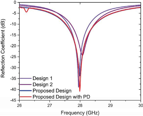
Figure 2 Simulation results for the reflection coefficient of the antenna Design 1, Design 2, slotted array design, and proposed design with PD.
Simulation results of Design 1, Design 2, slotted array design, and two element slotted array design with PD are presented in Fig. 2. Bandwidth increases from 0.7 GHz to 1.1 GHz due to incorporation of the DGS. Simulations are carried out in CST software with very fine mesh used for improving the accuracy of the simulation results.
3 FOUR-PORT MIMO SLOTTED MICROSTRIP PATCH ANTENNA DESIGN AND ANALYSIS
MIMO configuration of the proposed slotted array has been realized using four port excitations. The geometry includes four elements, where each element corresponds to the array geometry given in Fig. 1 (f). These four elements are arranged to form a four-port excitation suitable for MIMO operations as illustrated in Fig. 3 (a). The corresponding ground plane incorporates the DGS and is arranged as shown in Fig. 3 (b). The inclusion of slots significantly improves the MIMO characteristics, resulting in higher gain and stable radiation performance in the resonating frequency band. The size of the proposed MIMO configuration is mm3. Photographs of the fabricated prototype, showing top and back views, are presented in Figs. 3 (c) and (d).
Scattering (S) parameters are experimentally characterized using a Keysight N5224B PNA. Simulated and measured S-parameters are presented in Figs. 4 and 5. The obtained bandwidth from these results spans 27.45–28.55 GHz which falls within the 5G spectrum. The remaining MIMO elements demonstrate comparable reflection profiles, with only minor frequency shifts attributed to fabrication tolerances and mutual coupling effects. The measured impedance bandwidth is approximately 1.1 GHz. The transmission coefficient () characteristics, illustrated in the Fig. 5, confirm that the antenna system maintains sufficient isolation between ports. Isolation between ports is dB between Antenna 3 and Antenna 4. This validates the effective decoupling performance of the proposed MIMO configuration.
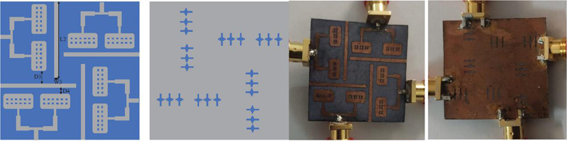
Figure 3 (a) Proposed four-port MIMO structure, (b) DGS based ground plane, (c) fabricated prototype of four-port MIMO antenna, and (d) fabricated prototype MIMO antenna DGS ground plane.
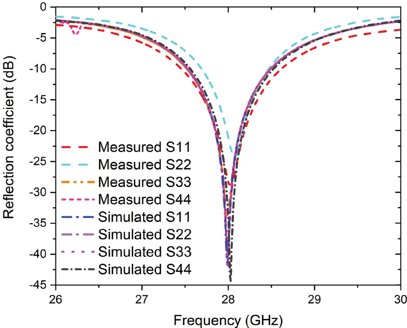
Figure 4 Simulated vs measured reflection coefficient of the proposed four-port MIMO antenna.
The simulated and measured results demonstrate strong agreement, confirming the performance characteristics of MIMO antenna. Minor discrepancies observed are primarily attributed to fabrication tolerances, connector losses, and the influence of coaxial cables during measurements. The measured performance validates the suitability and practical feasibility of the proposed MIMO antenna, particularly for 5G communication applications.

Figure 5 Simulated vs measured transmission coefficient of the proposed four-port MIMO antenna.
Figure 5 presents the simulated transmission characteristics of the configuration. From the measured results, the isolation between port 1 and port 2 is relatively low, with a similar trend observed between port 3 and port 4, owing to their close physical proximity and parallel orientation. Conversely, a notable improvement in isolation is achieved among the antenna pairs (1–3), (1–4), (2–3), and (2–4), indicating reduced mutual coupling between diagonally positioned elements. To further mitigate coupling effects, slots are incorporated into the structure. As shown in Fig. 5, the inclusion of these slots significantly enhances isolation between the radiating elements, achieving a minimum isolation better than 25 dB across the operational frequency band. For the measurements, 2.92 mm K-connectors are used, as these connectors are suitable for high frequency applications.
4 ANALYSIS OF THE MIMO ANTENNA WITH PRACTICAL REALIZATION AND EXPERIMENTAL RESULTS
It is essential to evaluate the performance in terms of the corresponding radiation characteristics. Accordingly, the polar radiation pattern plots for and are simulated in both E- and H-planes. Similarly, these patterns are measured using an experimental setup comprising an anechoic chamber. The measurement setup includes a horn antenna operating in the transmitting mode, while the designed antenna under test acts as the receiving antenna. The corresponding main lobe is positioned at in both the pattern plots presented in Figs. 6 (a) and (b) at 27.5 GHz and 28 GHz, respectively. Furthermore, the results indicate good agreement between the simulated and measured patterns. It is noteworthy that far-field measurement systems are typically less accurate for compact antennas of 5G frequencies where alignment sensitivity and chamber reflections can introduce additional measurement discrepancies.
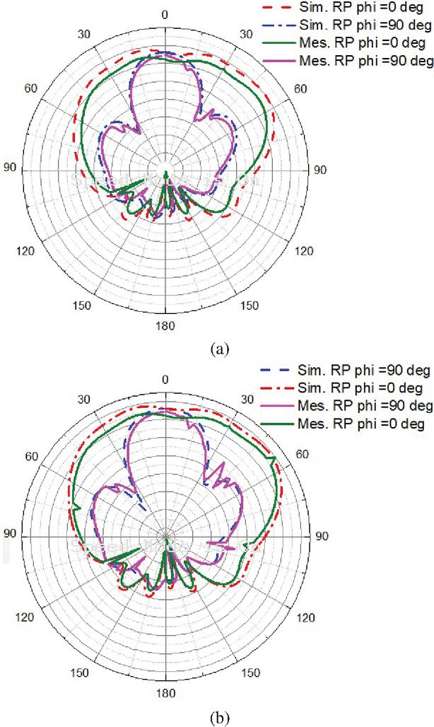
Figure 6 Simulation vs measured 2D radiation patterns of the proposed four-port MIMO antenna at (a) 27.5 and (b) 28 GHz.
The proposed four-port MIMO slotted array antenna reported a simulated peak gain of 10.1 dBi while the measured peak gain is 10.02 dBi for port 1. However, the antenna exhibits a stable 3 dB gain variation from 27.45–28.55 GHz.
5 MIMO PARAMETERS AND COMPARATIVE ANALYSIS OF THE PROPOSED ANTENNA
It is essential to evaluate the performance of MIMO antennas in terms of diversity parameters. Certain threshold levels for these parameters are well established in the literature and our current task is to compute and compare the proposed MIMO structure. The most relevant metrics are enveloper correlation coefficient (ECC), Mean Effective Gain (MEG), Channel Capacity Loss (CCL) and Directive Gain (DG), each having its own functional implication of the performance of the MIMO. For instance, ECC is responsible for quantifying the received signals with respect to the ports. Higher ECC indicates lower isolation. The larger values of ECC can degrade the performance of MIMO inducing mutual coupling. It is also possible to evaluate the spatial diversity through the computed ECC in MIMO antennas [21]. The computation is based on the received signal envelope, S-parameters, and the corresponding radiation pattern characteristics. The mathematical expression as a function of S-parameters is:
| (1) |
Figure 7 represents the simulated versus computed ECC of the proposed four-port MIMO antenna over the 26–30 GHz frequency band. ECC values for all port combinations remain extremely low, well below the critical threshold of 0.5 and, in most cases, below 0.005. That confirms the excellent isolation as well as minimal correlation between antenna elements. Such low ECC ensures that the antenna ports operate independently, enabling effective spatial and polarization diversity which are essential for enhancing MIMO channel capacity and overall link reliability.

Figure 7 Simulated vs calculated ECC of the proposed four-port MIMO antenna across all ports.
The ECC limit for practical antennas is 0.5, which is considered suitable for uncorrelated MIMO antennas [24]. DG is another crucial parameter of the MIMO antenna, as it is used for reliability and effectiveness of the received signal in multipath environments. Higher DG values indicate better isolation between the radiating elements in MIMO configuration. An improved DG enhances communication robustness, and higher DG values correspond to greater isolation between the antenna elements [29]. DG for multiple ports of the antenna is:
| (2) |
Figure 8 shows DG performance of the proposed four-port MIMO antenna in the 26–30 GHz frequency range. DG values remain consistently close to the ideal 10 dB throughout the band, demonstrating the array’s high diversity efficiency. Only minor variations are observed below 27 GHz and above 29 GHz, which are negligible and have no significant impact on system performance. The combination of near-ideal DG and very low ECC confirms the proposed four-port MIMO antenna is well suited for high-capacity and reliable 28 GHz MIMO communications.

Figure 8 Simulated vs calculated DG of the proposed four-port MIMO antenna across the ports.
Table 2 Comparison of the four-port MIMO antenna with previous work
| Ref. | Frequency | Size of the Antenna | Number of MIMO Ports | Gain (dBi) | ECC, DG (dB) |
| (GHz) | (mm) | ||||
| [20] | 28, 38 | 4 | 10.4 | 0.02, Not Provided | |
| [23] | 3.6 | 8 | 2.5 | 0.01 | |
| [24] | 28 | 4 | 13.1 | Not Provided | |
| [25] | 24 | 2 | 7.41 | 0.24, 9.7 | |
| [26] | 5.2 & 24 | 2 | 5 & 7.37 | Not Provided | |
| [27] | 30 | 2 | 7 | 0.4, Not Provided | |
| [28] | 28 | 2 | 8 | 0.13, 9.9 | |
| [29] | 28 | 4 | 8.3 | 0.01, Not Provided | |
| This Work | 28 | 4 | 10.02 | 0.0002, 9.9 |
CCL is one of the MIMO performance parameters which represents the channels capacity of the system during the correlation effect. CCL is:
| (3) | |
| (6) | |
| (7) | |
| (8) |
The calculated CCL of 0.4 bits/Hz is less than the practical standards for the operating frequency range and represents high throughput.
MEG represents the received power in the fading environment:
| (9) |
where represents the radiation efficiency, is the antenna port number and is the number of antenna elements. The practical standard for MEG is 3 to 12 dB. Calculated MEG for the proposed four-port MIMO antenna is 6.5 for all four ports.
Comparative parameters like operating frequency, size of the antenna, number of MIMO ports, gain in dBi, ECC, and DG (dB) are evaluated against the proposed four-port MIMO antenna. Results indicate that the proposed design demonstrates superior performance across various parameters compared to existing works, as summarized in Table 2. The simulated ECC and DG values are 0.0002 and 9.9 dB which represent the proposed four-port MIMO antenna is best candidate for MIMO mm-wave/5G applications.
6 CONCLUSION
This work presents a four-port MIMO slotted array microstrip patch antenna system designed for 5G mm-wave communication applications. Each port of the proposed MIMO configuration consists of a twoelement antenna with PD optimized to achieve enhanced gain, radiation efficiency, and compactness. The antenna operates effectively across the 27.45–28.55 GHz frequency range, offering a measured impedance BW of 1.1 GHz. The prototype demonstrates a peak measured gain of 10.02 dBi, validating its suitability for high throughput communication systems. To comprehensively evaluate MIMO performance, the key diversity parameters such as DG, ECC, CCL, and MEG were evaluated and all exhibit values within practically acceptable limits for reliable 5G operation. The obtained results confirm that the proposed four-port MIMO antenna possesses excellent radiation and diversity characteristics. Therefore, it is a promising design to operate in the 5G spectrum.
REFERENCES
[1] A. Kumar, P. Pattanayak, R. K. Verma, D. Sabat, and G. Prasad, “Two element MIMO antenna system for multiband millimeter-wave, 5G mobile communication, Ka-band, and future 6G applications with SAR analysis,” AEU Int. J. Electron. Commun., vol. 171, 2023.
[2] A. A. Althuwayb, M. Alibakhshikenari, B. S. Virdee, N. Rashid, K. Kaaniche, A. B. Atitallah, A. Armghan, O. I. Elhamrawy, C. H. See, and F. Falcone, “Metasurface-inspired flexible wearable MIMO antenna array for wireless body area network applications and biomedical telemetry devices,” IEEE Access, vol. 11, pp. 1039–1056, 2023.
[3] A. E. Farahat and K. F. A. Hussein, “Dual-band (28/38 GHz) wideband MIMO antenna for 5G mobile applications,” IEEE Access, vol. 10, pp. 32213–32223, 2022.
[4] T. S. Rappaport, S. Sun, R. Mayzus, H. Zhao, Y. Azar, K. Wang, G. N. Wong, J. K. Schulz, M. Samimi, and F. Gutierrez, “Millimeter wave mobile communications for 5G cellular: It will work!,” IEEE Access, vol. 1, pp. 335–349, 2013.
[5] J. L. Wang, T. Liu, X. Wang, M. Wei, and Y. H. Lu, “Four-port low-profile broadband antenna with fan-leaf slits and shorting pins for 5G mobile applications,” Journal of Electromagnetic Waves and Applications, vol. 38, no. 7, pp. 802–812, 2024.
[6] P. S. B. Shariff, P. R. Mane, P. Kumar, T. Ali, and M. G. N. Alsath, “Planar MIMO antenna for mmWave applications: Evolution, present status & future scope,” Heliyon, vol. 9, no. 2, Feb. 2023.
[7] P. Sharma, R. N. Tiwari, P. Singh, P. Kumar, and B. K. Kanaujia, “MIMO antennas: Design approaches, techniques and applications,” Sensors, vol. 22, no. 20, p. 7813, 2022.
[8] A. Ahmad, D.-Y. Choi, and S. Ullah, “A compact two elements MIMO antenna for 5G communication,” Sci. Rep., vol. 12, no. 1, Mar. 2022.
[9] M. E. Munir, S. H. Kiani, H. S. Savci, M. Marey, J. Khan, H. Mostafa, and N. O. Parchin, “A four element mm-wave MIMO antenna system with wide-band and high isolation characteristics for 5G applications,” Micromachines, vol. 14, no. 4, p. 776, 2023.
[10] N. Sghaier, A. Belkadi, I. B. Hassine, L. Latrach, and A. Gharsallah, “Millimeter-wave dual-band MIMO antennas for 5G wireless applications,” J. Infr. Millim. THz Waves, vol. 44, nos. 3–4, pp. 297–312, Apr. 2023.
[11] B. A. F. Esmail and S. Koziel, “Design and optimization of metamaterial based dual-band 28/38 GHz 5G MIMO antenna with modified ground for isolation and bandwidth improvement,” IEEE Antennas Wireless Propag. Lett., vol. 22, pp. 1069–1073, 2023.
[12] A. K. Singh and S. Pal, “Compact self-isolated extremely low ECC folded-SIW-based slot MIMO antenna for 5G application,” IEEE Antennas Wireless Propag. Lett., vol. 23, pp. 194–198, 2024.
[13] M. Aboualalaa and I. Mansour, “Dual-band end-fire four-element MIMO antenna array using split-ring structure for mm-wave 5G applications,” IEEE Access, vol. 11, pp. 57383–57390, 2023.
[14] K. P. Ray, M. D. Pandey, and S. Krishnan, “Determination of resonance frequency of hexagonal and half hexagonal microstrip antennas,” Microw. Opt. Technol. Lett., vol. 49, no. 11, pp. 2876–2879, Nov. 2007.
[15] D. Khan, A. Ahmad, and D.-Y. Choi, “Dual-band 5G MIMO antenna with enhanced coupling reduction using metamaterials,” Sci. Rep., vol. 14, no. 1, p. 96, Jan. 2024.
[16] A. K. Biswas, S. Biswas, S. Haldar, and A. Nandi, “A highly decoupled flexible 4-element MIMO antenna with band notched characteristics for ultra wide-band wearable applications,” AEU Int. J. Electron. Commun., vol. 173, no. 154985, Jan. 2024.
[17] S. F. Jilani and A. Alomainy, “Millimetre-wave T-shaped MIMO antenna with defected ground structures for 5G cellular networks,” IET Microw. Antennas Propag., vol. 12, pp. 672–677, 2018.
[18] N. Shoaib, S. Shoaib, R. Y. Khattak, I. Shoaib, X. Chen, and A. Perwaiz, “MIMO antennas for smart 5G devices,” IEEE Access, no. 6, pp. 77014–77021, 2018.
[19] H. Jiang, L. Si, W. Hu, and X. Lv, “A symmetrical dual-beam bowtie antenna with gain enhancement using metamaterial for 5G MIMO applications,” IEEE Photonics J., no. 11, pp. 1–9, 2019.
[20] M. M. Basha, P. Pradeep, G. Srinivasulu, and J. Syed, “Design of compact and high gain dual-band four-port MIMO antenna array for mm-wave 5G communications,” Results in Engineering, vol. 25, pp. 104–153, 2025.
[21] L. Liu, Y. F. Weng, S. W. Cheung, T. I. Yuk, and L. J. Foged, “Modeling of cable for measurements of small monopole antennas,” in Proceedings of the Loughborough Antennas Propagation Conference (LAPC), Loughborough, UK, pp. 1–4, 14–15 Nov. 2011.
[22] I. L. Savarianantham, G. A. A. Mary, A. S. Mazhar, S. Mishra, and G. Jothi, “SIW cavity-backed gain-enhanced circularly polarized metamaterial-loaded dual-band MIMO antenna for WLAN and 5G applications,” Applied Computational Electromagnetics Society (ACES) Journal, vol. 40, no. 4, pp. 363–372, Apr. 2025.
[23] Y. Yashchyshyn, K. Derzakowski, G. Bogdan, K. Nyzovets, D. Godziszewski, C. H. Kim, and B. Park, “28 GHz switched-beam antenna based on S-PIN diodes for 5G mobile communications,” IEEE Antennas Wirel. Propag. Lett., vol. 17, p. 225, 2018.
[24] S. X. Ta, H. Choo, and I. Park, “Broadband printed-dipole antenna and its arrays for 5G applications,” IEEE Antennas Wirel. Propag. Lett., vol. 16, pp. 2183–2186, 2017.
[25] A. Iqbal, A. Basir, A. Smida, N. K. Mallat, I. Elfergani, J. Rodriguez, and S. Kim, “Electromagnetic bandgap backed millimeter-wave MIMO antenna for wearable applications,” IEEE Access, vol. 7, pp. 111135–111144, 2019.
[26] Y. Sun and K. W. Leung, “Substrate-integrated two-port dual-frequency antenna,” IEEE Trans. Antennas Propag., vol. 64, pp. 3692–3697, 2016.
[27] M. S. Sharawi, S. K. Podilchak, M. T. Hussain, and Y. M. M. Antar, “Dielectric resonator-based MIMO antenna system enabling millimetre-wave mobile devices,” IET Microw. Antennas Propag., vol. 11, pp. 287–293, 2017.
[28] H. Jiang, L. Si, W. Hu, and X. Lv, “A symmetrical dual-beam bowtie antenna with gain enhancement using metamaterial for 5G MIMO applications,” IEEE Photonics J., vol. 11, pp. 1–9, 2019.
[29] M. Khalid, S. Iffat Naqvi, N. Hussain, M. Rahman, Fawad, S. S. Mirjavadi, M. J. Khan, and Y. Amin, “4-port MIMO antenna with defected ground structure for 5G millimeter wave applications,” Electronics, vol. 9, p. 71, 2020.
[30] R. Anandan, V. V. Kumar, M. P. Maharajan, and G. Jothi, “Dual-beam series-fed MIMO antenna with metasurface loading for 5G sub-6 GHz access point applications,” Applied Computational Electromagnetics Society (ACES) Journal, vol. 40, no. 10, pp. 1045–1054, Oct. 2025.
[31] Z. Khan, C. Zhang, S. U. Rahman, X.-C. Wang, L. Wen, and W.-Z. Lu, “A low cost, wideband, microstrip patch antenna array with improved gain for millimeter-wave applications,” Applied Computational Electromagnetics Society (ACES) Journal, vol. 40, no. 10, pp. 1037–1044, Oct. 2025.
BIOGRAPHIES

Venkatrao Kolli is currently pursuing his Ph.D. in Electronics at Sathyabama Institute of Science and Technology, Chennai, India. His research interests include antenna array design, 5G communication, and wireless communication systems. He has published several research papers in peer-reviewed international journals and conferences in these areas. He is presently working as an Assistant Professor in the Department of Electronics and Communication Engineering at S R K R Engineering College, Bhimavaram. He has guided numerous undergraduate projects related to RF engineering and smart communication systems.

Merlin Sheeba G received her B.E. (Electronics and Communication) degree in 2003 from National Engineering College, Kovilpatti under MS University, India, and M.E. degree in 2005 from Karunya Institute of Science and Technology, Coimbatore under Anna University. She obtained her Ph.D. degree from Sathyabama University, Chennai, in 2017. She has 18 years of teaching and research experience. She is currently working as Professor in the Department of ECE, Jerusalem College of Engineering Chennai. She has published around 45 publications in national and international journals, conferences, and book chapters. Among them, 33 are Scopus indexed, five SCI indexed, and six Web of Science indexed. Her research interests are wireless networks, antennas, IOT and embedded systems. She has published four patents and a sanctioned Government project. She is an invited reviewer in reputable international conferences and journals.
ACES JOURNAL, Vol. 41, No. 4, 353–360
DOI: 10.13052/2026.ACES.J.410407
© 2025 River Publishers