A Fast LO Leakage Calibration Method for MIMO Transmitter
Jianhong Xie1, 2, Zhaopeng Fu3, Zhengbo Jiang1*, Jingxin Liu2, and Zhangcheng Hao1
1School of Information Science and Engineering Southeast University, Nanjing 210096, China
230198975@seu.edu.cn, jzb@seu.edu.cn, zchao@seu.edu.cn
2Transcom (Shanghai) Technology Co. Ltd. Shanghai 201600, China
jingxin.liu@transcom.net.cn
3Aqronos (Nanjing) Optical Integrated Chip Technology Co. Ltd. Nanjing 210000, China
frode928@gmail.com
∗Corresponding author
Submitted On: November 22, 2025
Accepted On: June 15, 2026
ABSTRACT
Local oscillator (LO) leakage caused by in-phase/quadrature (I/Q) offsets severely degrades the performance of direct-conversion multiple-input multiple-output (MIMO) transmitters in 5G and emerging 6G systems. Existing LO leakage calibration methods often require many measurements or suffer from slow convergence, making them inefficient for multi-channel and multi-frequency applications. To address this challenge, this paper proposes a fast LO leakage calibration method based on Newton’s method. For each channel at each frequency point, the I/Q offset compensation values are determined from only nine groups of I/Q settings and the corresponding LO leakage measurements. Simulations and experiments on an 8-channel MIMO transmitter show that the proposed method achieves an average LO leakage suppression of 55.6 dBc while reducing the number of calibration samples by more than 95% compared with traditional methods, demonstrating its efficiency and practicality for large-scale MIMO transmitters in 5G and 6G communications.
Keywords: Calibration, in-phase/quadrature offset, local oscillator leakage, multiple-input multiple-output transmitter, Newton’s method..
1 INTRODUCTION
Massive multiple-input multiple-output (MIMO) technology is widely regarded as one of the key enabling technologies for 5G and future 6G systems. A MIMO system configured with hundreds or even thousands of antennas can significantly enhance wireless communication performance [1, 2, 3]. In MIMO systems, direct-conversion transmitters (DCTs) [4] are commonly employed due to their high integration, low cost, and low power consumption. However, the in-phase/quadrature (I/Q) DC offsets in DCTs cause local oscillator (LO) leakage, which results in transmitter performance degrade [5, 6]. The LO leakage signal cannot be directly eliminated by a filter, since it falls within or near the signal bandwidth in a DCT. Therefore, it is essential to calibrate the I/Q offsets to effectively suppress LO leakage signal.
For large-scale MIMO systems, a key challenge is the trade-off between calibration effectiveness and calibration time. In practical systems, calibration must be performed over multiple transmitter channels and multiple operating frequency points. As a result, the total calibration time scales with channels, frequency points, and measurements required at each frequency point. Although accurate LO leakage calibration is essential, many existing methods require excessive calibration time, which limits their practical applicability in large-scale MIMO systems. Therefore, it is highly desirable to develop a fast calibration method that achieves a favorable trade-off between calibration effectiveness and calibration time.
Existing LO leakage calibration methods can be broadly classified into traversal-based and estimation-based techniques. In traversal-based methods, [7] uses a detector feedback loop to search for proper I/Q offsets, while [5] employs a complex receiver feedback loop with frequency offset for LO leakage calibration. Although effective, such methods usually require exhaustive searches over the calibration space, resulting in long calibration time, especially in multi-channel and multi-frequency MIMO systems.
Estimation-based techniques have also been investigated. A blind technique based on higher-order statistics introduced in [4] estimates the calibration parameters using gradient descent, but may suffer from slow convergence and sensitivity to initialization and noise. The method in [8] performs compensation using specially designed training sequences, which limits implementation flexibility. Joint transmitter and receiver calibration is performed in [9, 10] with high computational complexity and unavoidable error propagation. Reference [11] combines least squares and gradient descent methods, but multiple candidate solutions and the need for phase information further increase calibration complexity.
Although these studies provide useful solutions for LO leakage calibration, several limitations remain for large-scale MIMO transmitters. Many existing methods mainly focus on single-channel calibration and do not explicitly consider the stringent calibration-time requirement in multi-channel systems. Moreover, the trade-off among low sample complexity, fast calibration speed, and sufficiently high LO leakage suppression has not been adequately addressed for practical deployment.
To overcome these limitations, this paper proposes a fast LO leakage calibration method based on Newton’s method for MIMO transmitter systems. The main contributions of this work are summarized as follows: a fast LO leakage calibration method for MIMO transmitters is developed, which is particularly suitable for systems with numerous channels and frequency points; a Newton-based estimation scheme is developed to determine the I/Q offset compensation values; a nine-point measurement strategy is designed to balance calibration effectiveness and calibration time; experimental results demonstrate the effectiveness and efficiency of the proposed method.
The rest of the paper is organized as follows. Section 2 introduces the system model and the mechanism of LO leakage. Section 3 presents the proposed Newton-based LO leakage calibration method. Section 4 presents the simulation and experimental results of the LO leakage in an 8-channel MIMO transmitter system. Section 5 concludes the paper.
2 SYSTEM MODEL
The system model of the LO leakage calibration of DCTs in a MIMO transmitter system is illustrated in Fig. 1. The I/Q signals and are mixed with the LO signals to obtain the RF output signals , where represents the th transmitter channel, and represent the DC offsets corresponding to I and Q branch introduced due to the I/Q mixer or I/Q modulator in the th transmitter channel and, accordingly, and , generated from digital-to-analog converters (DACs), are the target compensating voltages to the th transmitter channel for the LO leakage calibration.
The RF output signal of the th transmitter channel, ignoring the influence of I/Q imbalance, can be expressed as
| (1) |
where represents the channel gain of the th transmitter channel.
Ideally, the power of LO leakage signal is
| (2) |
The simulated variation of the LO leakage level with I/Q offsets is shown in Fig. 2, where I and Q offsets correspond to and in (2). It is clearly shown that the LO leakage level is minimized when and are zero. However, and cannot be equal to zero in practice, and therefore should be compensated by and to minimize the LO leakage level. After calibration, equation (2) can be adjusted to
| (3) |
Obviously, the LO leakage calibration can be completed by finding out the values satisfying and .
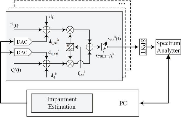
Figure 1 System model of MIMO DCT system with calibration circuit.
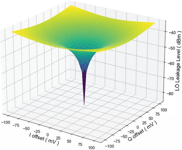
Figure 2 Simulated LO leakage level versus I/Q offsets.
3 CALIBRATION ALGORITHM
As shown in Fig. 1, the PC controls the DACs to generate a set of compensating voltages for various transmitter channels. The spectrum analyzer measures the corresponding LO leakage levels and reports back to the PC. The proposed calibration algorithm based on Newton’s method computes the optimized compensating voltages required to minimize the LO leakage levels.
Taking one transmitter channel as an example, for the th measurement, , applying different I/Q offsets () and measured LO leakage power , a set of equations can be obtained
| (4) |
where, for simplicity, the channel superscript is omitted, and the gain is a fixed constant for this channel. Set the 0th measurement as the reference, then
| (5) |
Subtracting the two equations in (5), i.e., , yields
| (6) |
where and .
Under the ideal noiseless model, all lines in (6) will intersect at a single point (). The target value for the LO leakage calibration can be obtained by determining the intersection point. However, the lines cannot intersect at a single point due to non-ideal physical conditions, such as hardware noise and measurement errors. Instead, an optimization algorithm can be employed to identify a point () that minimizes the sum of the squares of the distances from this point to the set of lines. This approach yields the point with the smallest error relative to the theoretical target point .
Let , equation (6) can be simplified as
| (7) |
For a candidate point as the target point, the square of its distance from the lines in (7) can be expressed as
| (8) |
For convenience, define , the objective function is the sum of (8)
| (9) |
where represents set of I/Q offsets, represents lines in (6).
The target point for the LO leakage calibration will be found as soon as the point is found which can minimize in (9).
First, the gradient of the objective function is calculated
| (10) |
Second, calculate the Hessian matrix
| (11) |
Since is quadratic, the Hessian matrix is constant and positive semidefinite. When the measurement points are chosen such that the resulting lines are not all parallel, the Hessian becomes positive definite, and the minimizer is unique. Therefore, the solution of (9) can be approximated gradually by iteration based on Newton’s method. The iterative formula for Newton’s method is
| (12) |
The iteration starts from as the values of I/Q offsets for LO leakage calibration are usually very small, and stops when the norm of the update falls below a prescribed threshold.
The impact of the number of I/Q offset configurations on LO leakage calibration results under different LO leakage power errors, based on the proposed method, is simulated first. As shown in Fig. 3, the smaller the LO leakage power measurement error (e.g., when ), the better the LO leakage calibration results. The trend indicates that increasing number of I/Q offset points can improve the LO leakage calibration result. When 8–10 sets of I/Q offset configurations are selected, the calibration performance is about 10 dB worse compared to selecting 20–40 sets. Nine sets of I/Q offset configurations are adopted in this work as a compromise between the LO leakage calibration performance and the total calibration time.
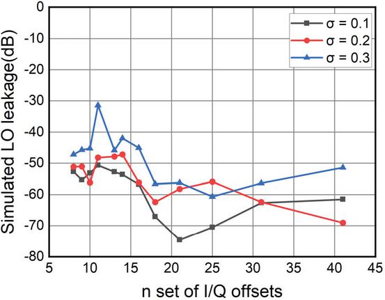
Figure 3 Simulation of the impact of the number of I/Q offset configurations on LO leakage calibration results under different LO leakage power errors.
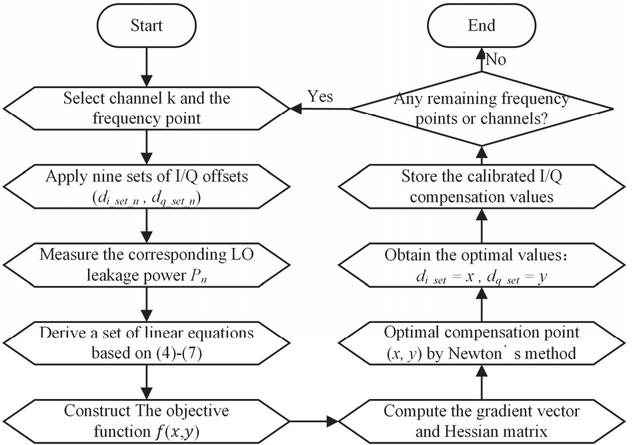
Figure 4 Flowchart of the proposed Newton-based LO leakage calibration method for the MIMO transmitters.
The detailed procedure of the proposed LO leakage calibration method for MIMO transmitters is illustrated in Fig. 4. The calibration process is summarized as follows.
S1: Select channel and the target frequency point. Apply nine sets of I/Q compensation voltages (), and measure corresponding LO leakage power .
S2: Based on the measured data, derive a set of linear equations according to (4)–(7).
S3: Construct the objective function , which is defined as the sum of the squared distances from a candidate point to the derived lines.
S4: Compute the gradient vector and Hessian matrix of , and use Newton’s method to determine the optimal compensation point . The obtained result is taken as the optimal compensation values.
S5: The same procedure is repeated for all remaining channels and frequency points until the calibration process is completed.
4 EXPERIMENTAL RESULTS
Figure 5 shows the experimental scenario for LO leakage calibration, which consists of an 8-channel MIMO transmitter system, a PC running the calibration algorithm, a signal analyzer for measuring LO leakage levels under different I/Q offsets in each channel, and a switching matrix for selecting and switching between different channels.
Table 1 lists the LO leakage levels corresponding to different I/Q compensating voltages () in a single transmitter channel. The nine I/Q offset combinations () are carefully chosen to evenly cover the range of possible I/Q offsets, balancing calibration accuracy with calibration time. Following the steps in section 3, seven lines are derived, and then the point that can minimize the sum of the squared distances from the seven lines is identified using Newton’s method. The seven lines that roughly intersect at one point are depicted in Fig. 6. The point calculated using Newton’s method () is very close to the manually measured point .
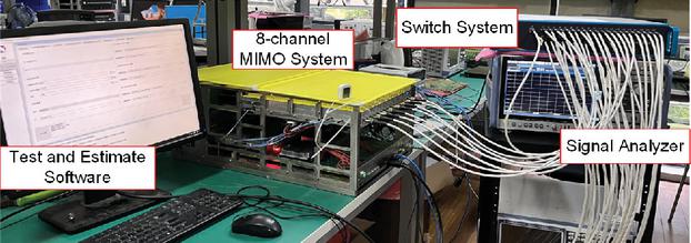
Figure 5 Experimental scenario.
Table 1 Measured LO leakage level at 9 I/Q offsets
| No. | I Offset | Q Offset | LO Leakage |
| (mV) | (mV) | Level (dBm) | |
| 1 | 0 | 0 | -19.18 |
| 2 | 0 | +0.1 | -15.54 |
| 3 | 0 | -0.1 | -13.30 |
| 4 | +0.1 | 0 | -11.33 |
| 5 | +0.1 | +0.1 | -10.88 |
| 6 | +0.1 | -0.1 | -9.34 |
| 7 | -0.1 | 0 | -25.32 |
| 8 | -0.1 | +0.1 | -15.71 |
| 9 | -0.1 | -0.1 | -15.30 |
Table 2 compares the I/Q compensating voltages for LO leakage calibration between manually measured and the proposed method for different transmit channels in the 8-channel MIMO system. The proposed method exhibits high consistency with the manually measured values, with an average error of only 2 mV. The results demonstrate the effectiveness of the proposed calibration technique for MIMO transmitter LO leakage suppression in MIMO transmitter systems.
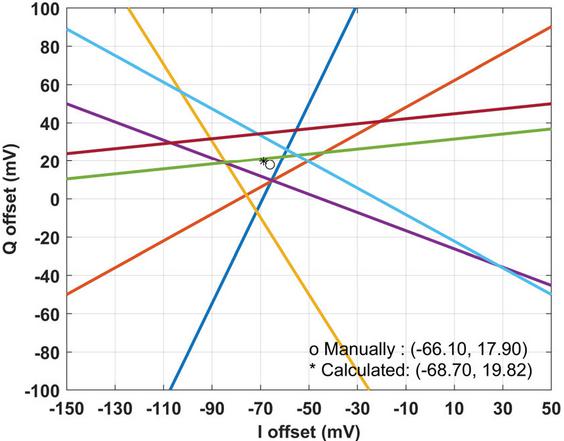
Figure 6 Calculated and manually measured I/Q compensation values for LO leakage calibration.
Table 2 Comparison of calculated and manually measured I/Q offsets
| Channel | Newton’s Method | Manually Test | ||
| I(mV) | Q(mV) | I(mV) | Q(mV) | |
| 1 | -68.70 | 19.82 | -66.1 | 17.9 |
| 2 | -49.05 | -15.78 | -51.2 | -17.3 |
| 3 | -57.31 | -10.76 | -59.3 | -12.5 |
| 4 | -62.16 | 7.01 | -63.7 | 7.4 |
| 5 | -54.30 | -3.45 | -55.7 | -3.3 |
| 6 | -51.10 | -10.80 | -52.5 | -12.3 |
| 7 | -65.51 | 32.27 | -68.8 | 31.3 |
| 8 | -55.29 | -3.73 | -57.3 | -3.3 |
The eight I/Q offset calibration values for the 8-channel transmitter, obtained using the proposed method, are applied to the MIMO transmitter system for LO leakage testing. For comparison, the LO leakage without calibration and that with manually calibration are also measured under the same experimental conditions, as shown in Fig. 7.
It can be observed that the proposed method significantly suppresses the LO leakage for all eight transmitter channels compared with the uncalibrated case. Although manual calibration achieves a lower average LO leakage of about 70 dBc, the proposed Newton-based method reduces the average LO leakage of the eight channels to approximately 55.6 dBc, while requiring only nine samples. These results demonstrate that the proposed method provides a favorable trade-off between calibration performance and measurement efficiency in multi-channel MIMO transmitter systems.
Generally, measurement instruments require a signal-to-noise (SNR) in the range of 40 to 52 dBc [12, 13], while the most stringent SNR requirement specified in 3GPP for 5G mobile communication is 35 dBc [14]. Therefore, the calibrated LO leakage level of 55.6 dBc satisfies both instrument-grade SNR requirements and practical communication system requirements.
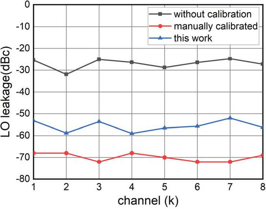
Figure 7 Measured LO leakage of the 8-channel MIMO transmitter without calibration, with traversal-based and with proposed Newton-based calibration.
Table 3 further compares the proposed method with representative existing methods in terms of LO leakage suppression, sample number, applicability, and total calibration time. The proposed method achieves an average LO leakage of 55.6 dBc with only nine samples per frequency point per channel, which is comparable to or better than the reference methods while significantly reducing the sample number by more than 95%. In particular, under the unified assumption of eight channels, 100 frequency points per channel, and 50 ms for each set of I/Q compensation values, the total calibration time of the proposed method is only about 0.1 hour (6 minutes). By contrast, the reported methods cost more than 2 hours due to their much higher sample complexity. This result demonstrates the advantage of the proposed method in achieving a good trade-off between calibration performance and calibration time, especially for multichannel MIMO transmitter systems.
Table 3 Comparison of calibration results
| Item | Calibration | LO Leakage | Type | Samples per | Channels | Total Calibration |
| Method | (dBc) | Frequency Point | Time∗ (hour) | |||
| [4] | Gradient descent | 52 | Chip-level tested | 10000 | 1 | 1111 |
| [5] | Traversal-based | 100 | Simulated | 512 | 1 | 5.73 |
| [7] | Traversal-based | 45 | Chip-level tested | 180 | 1 | 2 |
| [9] | Least squares | 52 | Chip-level tested | 1000 | 1 | 11.07 |
| [11] | Least squares gradient descent | 53 | System-level tested | 40000 | 1 | 444 |
| [10] | Joint digital online compensation | 58 | Chip-level tested | 64 | 1 | /(online) |
| This Work | Newton’s method | 55.6 (average) | System-level tested, 8-channel, RF out | 9 | 8 | 0.1 |
| ∗Total calibration time is calculated for an 8-channel system with 100 frequency points per channel, assuming that each set of I/Q compensation values requires 50 ms. | ||||||
5 CONCLUSION
A novel fast LO leakage calibration technique for the MIMO transmitter system based on Newton’s method is proposed in this paper. By measuring nine sets of I/Q offsets and the corresponding LO leakage levels, the I/Q offset values for its LO leakage calibration can be accurately and efficiently computed. Experiments on an 8-channel MIMO transmitter system demonstrate that the proposed method achieves an average LO leakage of 55.6 dBc after calibration, requiring only nine samples per frequency point per channel. These results underscore the method’s fast and effective performance, making it well-suited for largescale MIMO systems in 5G and 6G communications.
ACKNOWLEDGMENT
This work was supported by the National Key R&D Program of China under Grant 2023YFF0717804 and by the Fundamental Research Funds for the Central Universities under Grant 2242022k60008.
REFERENCES
[1] S. Suyama, T. Okuyama, N. Nonaka, and T. Asai, “Recent studies on massive MIMO technologies for 5G evolution and 6G,” in 2022 IEEE Radio and Wireless Symposium (RWS), 16–19 Jan. 2022.
[2] M. Rajakumar and M. Meena, “A novel design for four-port metamaterial SRR-loaded MIMO antenna for 5G and wireless communication applications,” Applied Computational Electromagnetics Society (ACES) Journal, vol. 39, no. 12, pp. 1059–1065, Dec. 2024.
[3] F. Peng, F. Yang, B. Liu, and X. Chen, “Experimental investigation of decoupling effect on the nonlinearity of power amplifiers in transmitter array,” Applied Computational Electromagnetics Society (ACES) Journal, vol. 38, no. 01, pp. 7–14, Jan. 2023.
[4] Z. Zhu, X. Huang, M. Caron, and H. Leung, “Blind self-calibration technique for I/Q imbalances and DC-offsets,” IEEE Transactions on Circuits and Systems I: Regular Papers, vol. 61, no. 6, pp. 1849–1859, 2014.
[5] S. Zhang, Y. Tian, P. Ye, L. Guo, H. Zeng, and H. Li, “A novel calibration method of DC-offsets in direct-conversion transmitter,” IEEE Communications Letters, vol. 26, no. 11, pp. 2745–2749, 2022.
[6] A. A. Abidi, “Direct-conversion radio transceivers for digital communications,” IEEE Journal of Solid-State Circuits, vol. 30, no. 12, pp. 1399–1410, 1995.
[7] C. Lanschutzer, A. Springer, L. Maurer, Z. Boos, and R. Weigel, “Integrated adaptive LO leakage cancellation for W-CDMA direct upconversion transmitters,” in IEEE Radio Frequency Integrated Circuits (RFIC) Symposium, 9–10 June 2003.
[8] C. J. Hsu and W. H. Sheen, “Joint calibration of transmitter and receiver impairments in direct-conversion radio architecture,” IEEE Transactions on Wireless Communications, vol. 11, no. 2, pp. 832–841, 2012.
[9] J. H. Deng, C. F. Lee, M. L. Ku, and J. K. Hwang, “Self-calibration of joint RF impairments in a loopback wideband transceiver,” IEEE Access, vol. 8, pp. 45607–45617, 2020.
[10] H. C. Liu, Z. C. Huang, N. G. Doan, C. W. Jen, and S. J. J. Jou, “Joint digital online compensation of TX and RX time-varying I/Q mismatch and DC-offset in mmWave transceiver system,” IEEE Transactions on Circuits and Systems I: Regular Papers, vol. 69, no. 2, pp. 919–932, 2022.
[11] Z. Zhu, X. Huang, and H. Leung, “Joint I/Q mismatch and distortion compensation in direct conversion transmitters,” IEEE Transactions on Wireless Communications, vol. 12, no. 6, pp. 2941–2951, 2013.
[12] Keysight, “MXG X-series signal generator N5181B analog & N5182B vector,” Feb. 2023.
[13] Rohde & Schwarz, “SMBV100B vector signal generator,” Sep. 2024.
[14] 3GPP, “Base Station (BS) radio transmission and reception,” Jan. 2025.
BIOGRAPHIES

Jianhong Xie was born in Nantong, Jiangsu, China, in 1987. She received the B.S. degree in applied physics from Nanjing University of Posts and Telecommunications, Nanjing, in 2010, and the M.S. degree in electronics and communication engineering from Southeast University, Nanjing, in 2018. She is currently pursuing the Ph.D. degree in electromagnetic field and microwave technology at Southeast University, Nanjing. Her major research interests include RF system design, microwave circuit development, and MIMO communication technologies. Since 2013, she has been with Transcom (Shanghai) Technology Co. Ltd., where she serves as senior engineer, focusing on research and development of RF and microwave technologies. She has led or participated in several national major projects.

Zhaopeng Fu was born in Lianyungang, Jiangsu, China, in 1986. He received the B.S. degree in electronic information science and technology from Nantong University, Nantong, in 2009, and the M.S. degree in electronics and communication engineering from Southeast University, Nanjing, in 2019. His major research interests include RF system design, microwave circuit development, and LiDAR system development. Since 2021, he has been with Yuanjiang (Nanjing) Photonic Integrated Circuit Technology Co. Ltd., where he serves as R&D Director, focusing on research and development of RF and microwave technologies and FMCW LiDAR. He has led or participated in several major projects.

Zhengbo Jiang was born in Jiangsu, China, in 1980. He received the B.S. degree in radio engineering and the M.S. and Ph.D. degrees in electromagnetic field and microwave technique from Southeast University, Nanjing, in 2002, 2004, and 2009, respectively. In 2023, he was a Short-Term Visiting Scholar with the University College London, UK. He is currently a professor with the School of Information Science and Engineering. His current research interests include over-the-air testing, channel emulation, microwave measurement, antenna measurement, and measurement instruments. He was a recipient of the National Science and Technology Progress Prize in 2023 and the FirstClass Science and Technology Prize of Jiangsu Province in 2020. He is a senior member of CIE and a member of the CIE Young Scientists Club.

Jingxin Liu was born in Baotou, Inner Mongolia, China, in 1993. He received the B.S. degree in Microelectronics from Nanjing University, Nanjing, in 2015. Since 2015, he has been with Transcom (Shanghai) Technology Co. Ltd., where he has been engaged in the research and development of channel emulator design and wireless channel simulation technologies. His current research focuses on channel emulation for MIMO wireless communication systems, and the development and optimization of related instrumentation.

Zhangcheng Hao received the B.S. degree in microwave engineering from XiDian University, Xi’an, China, in 1997, and the M.S. and Ph.D. degree in radio engineering from Southeast University, Nanjing, in 2002 and 2006, respectively. In 2006, he was a Postdoctoral Researcher with the Laboratory of Electronics and Systems for Telecommunications (LEST), École Nationale Supérieure des Télécommunications de Bretagne (ENSTB), Bretagne, France, where he was involved with developing millimeter-wave antennas. In 2007, he joined the Department of Electrical, Electronic and Computer Engineering, Heriot-Watt University, Edinburgh, UK, as a Research Associate, where he was involved with developing multilayer integrated circuits and ultra-wide-band components. In 2011, he joined the School of Information Science and Engineering, Southeast University, Nanjing, as a professor, and as a chief-professor in 2019. He holds 30 granted patents and has authored and coauthored over 200 referred journal and conference papers. His current research interests involve microwave and millimeter-wave systems, super-massive and super-wideband phased array antennas, and submillimeter-wave and terahertz components and systems.
ACES JOURNAL, Vol. 41, No. 5, 480–487
DOI: 10.13052/2026.ACES.J.410510
© 2026 River Publishers