Design of All-Dielectric Resonant Metasurface Receiver for Millimeter-Wave Front-Ends
Qiwei Liu1, Dan Shi1,*, Yanchi Liu1, Jintao He1, Hongbo Tao2,*, Xiaoyong Liu2, Zhonghua Xin3, and Yuhao Jia3
1School of Electronic Engineering Beijing University of Posts and Telecommunications, Beijing 100876, China 272044242@qq.com, shidan@bupt.edu.cn, lyc2023018011@bupt.edu.cn, hejint2024@163.com
2State Radio Monitoring Center Testing Center, Beijing 102609, China taohongbo@srtc.org.cn, liuxiaoyong@srtc.org.cn
3China Coal Research Institute, Beijing 101320, China en55015@hotmail.com, jiayuhaobuaa@163.com
∗Corresponding Authors
Submitted On: November 23, 2025; Accepted On: April 20, 2026
ABSTRACT
In recent years, high-power millimeter waves (HPMMW) have emerged as a severe electromagnetic disturbance that endangers telecommunication networks significantly, as the intense electromagnetic interference induced by HPMMW can damage metallic electronic circuits and front-end devices. To address this issue, this paper proposes an all-dielectric resonant metasurface-based front-end system that enables millimeter-wave components to resist HPMMW-induced damage. The system comprises a laser, an all-dielectric metasurface, an electro-optic resonator, a photodetector, and electronic circuitry. A cell-array metasurface antenna is used to capture and transmit a 65 GHz millimeter-wave signal to an electro-optic field sensor. Subsequently, the photodetector converts the optical signal into a demodulated radio-frequency signal, which can be further processed by the subsequent electronic circuitry. With a compact footprint of and a high receiver sensitivity of 52 dBm, the proposed system can be integrated with other electronic circuits, facilitating the miniaturization of telecommunication equipment.
Keywords: All-dielectric metamaterials, Fano resonant effect, high-power millimeter wave (HPMMW), radio frequency front-end..
1 INTRODUCTION
Millimeter waves have been widely utilized in 5 G communication, radar sensors, radio astronomy, remote sensing, imaging, and security screening [1, 2, 3]. Millimeter-wave transmitters and receivers are key components for system performance. Meanwhile, high-power millimeter waves (HPMMW) generated by vacuum-electronic traveling-wave tubes or sheet electron beams pose a severe threat to communication systems [4, 5]. HPMMW can disrupt millimeter-wave communication networks by inducing intense electromagnetic interference that damages or destroys electronic circuits.
Therefore, the protection of millimeter-wave systems against HPMMW has become increasingly significant. Since most radio front-end components operating at the millimeter-wave band are typically made of metal [6, 7], HPMMW generates a large current surge that inflicts catastrophic damage by melting metallic interconnects.
According to published literature, an effective method is to apply electromagnetic shielding [8, 9, 10]. Although the shield can effectively attenuate electromagnetic energy, millimeter-wave components remain vulnerable because the shield and parts of the components are made of metal, which is meltable under HPMMW. Moreover, the protection circuits that use transient-voltage-suppression (TVS) diodes or metal-oxide varistors (MOV) [11] also perform poorly. A novel circuit with ultra-low capacitance was presented and fabricated using an InGaP/GaAs heterojunction bipolar transistor [11]. Although this Darlington pair is suitable for high-frequency protection from HPMMW, it often works below 20 GHz. In addition, specialized protection modules for electrical equipment against high-altitude electromagnetic pulses (HEMP) and intentional electromagnetic interference (IEMI) have been developed and verified through practical testing, providing feasible engineering solutions for electromagnetic interference shielding [12]. In recent years, an all-dielectric front-end structure has been proposed to replace the metallic antenna, particularly suitable for HPMMW applications. Traditionally, the dielectric resonant antenna (DRA) has been investigated in detail [13, 14]. Hsu et al. proposed an effective all-dielectric photonic-assisted radio front-end structure [13]. A device combining an electro-optic crystal field sensor with a textbook DRA was developed, which captured the free-space centimeter-wave RF signal (7.38 GHz) and generated an enhanced electric field on the structure’s surface. While this design maintains HPMMW immunity and reasonable receiver sensitivity, it is not optimized for millimeter-wave applications and miniaturized designs. In terms of compact and wideband millimeter-wave antenna design, recent studies have made notable progress. A compact, circularly polarized, crossed-dipole antenna with wide bandwidth was proposed using a split-ring resonator and parasitic patches, providing a valuable reference for miniaturized millimeter-wave front-end antenna design [15]. Meanwhile, a three-dimensional, compact, propeller-shaped, circularly polarized ceiling antenna was developed, further enriching the options for compact antenna structures in communication systems [16]. These works highlight the importance of structural optimization in achieving compact size and excellent performance, aligning with the design goals of the proposed metasurface receiver.
In this paper, an optimized receiver model operating at millimeter-wave frequencies using a metasurface structure is proposed. The proposed receiving antenna exhibits strong resonance at 65 GHz and a small size of . Meanwhile, compared with traditional DRA antennas, dielectric metasurfaces are much smaller. Presently, metamaterials have been widely applied in antenna design, including minimized cavity resonators, wave-guiding structures, angular-independent surfaces, terahertz switches, and fluid-tunable frequency-agile materials [17, 18, 19, 20].
All-dielectric metasurface front-end technologies and the whole system are introduced in section 2. Metasurface resonant theory, design of the metasurface antenna, and electro-optic (EO) resonators are illustrated in section 3. Simulation results and parametric discussions are presented in section 4. System performance, including system sensitivity measurements, is provided in section 5, followed by the conclusion in section 6.
2 RECEIVER DESIGN AND ANALYSIS
2.1 All-dielectric photonic-assisted radio front-end receiver design
An all-dielectric resonant metasurface receiver is proposed to receive a millimeter-wave signal, immune to HPMMW, while maintaining high receiver sensitivity. As shown in Fig. 1, the photonic-assisted all-dielectric radio-frequency (RF) front-end receiver comprises a laser, a dielectric metasurface, an EO resonator, a photodetector, and electronic circuitry.

Figure 1 Components of the all-dielectric photonic-assisted radio front-end receiver.
The incident millimeter-wave signal interacts with the dielectric metasurface, which generates a Fano resonance and consequently an electric-field enhancement at the top of the metasurface. To effectively convert the RF millimeter-wave signal to an optical signal via the LiNbO3 electro-optic disk resonator, the system uses a diamond prism to couple the input optical beam from the laser into the EO resonator. This resonator is positioned in the region of maximum electric-field enhancement on the metasurface to efficiently convert the received millimeter-wave signal into an optical signal. This coupling method is crucial for enabling the subsequent photodetection and signal processing stages [13, 14, 15, 16, 17, 18, 19, 20, 21], as shown in Fig. 2.
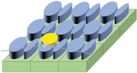
Figure 2 Using a diamond prism to couple the input optical beam to the EO resonator.
The photodetector converts the optical signal into a demodulated RF signal, which can be further processed by the subsequent electronic circuitry [13, 14, 15, 16, 17, 18, 19, 20, 21, 22]. In the entire receiver system, the optical signal is coupled into and transmitted through an optical fiber, thereby enhancing immunity to HPMMW [13].
2.2 Impact factor analysis of receiver sensitivity
Receiver sensitivity is defined as the minimum detectable incident power when the system carrier-to-noise ratio (CNR) is equal to 1, which can be calculated as [13]:
| (1) |
where is the cross-sectional area of the metasurface antenna, and is the wave impedance of free space ().
The incident root-mean-square (RMS) RF electric field can be written as [13]:
| (2) |
where and are the dielectric constants of and the metasurface antenna, respectively, at microwave frequencies, and is the field-enhancement factor, which is defined as the ratio of the metasurface-enhanced field strength to the incident free-space field [13].
The electric field experienced by the electro-optic resonator can be obtained by the formula of the modulation depth under the condition of [13, 14, 15, 16, 17, 18, 19, 20, 21, 22]:
| (3) | |
| (4) | |
| (5) | |
| (6) |
where is the electro-optic resonator finesse (, is the loaded quality factor), is the refraction index of electro-optic resonator at the operation wavelength , is the electro-optic coefficient, is the circumference of the electro-optic disk resonator (), is the photodetector responsivity, is the input optical power, is the average optical power at the detector (, is the total variance of noise current generated by relative intensity noise (RIN) power of the source laser (), shot noise (), and thermal noise power (the thermal noise is negligible because the received power is high enough), is relative intensity noise of the source laser, is the elementary charge of , and is the detection bandwidth [13, 14, 15, 16, 17, 18, 19, 20, 21, 22]. is given by:
| (7) |
Therefore, receiver sensitivity, namely the minimum detectable incident power per unit bandwidth, is given by:
| (8) |
According to (8), better receiver sensitivity can be obtained by increasing the field-enhancement factor and average optical power , as well as decreasing the metasurface antenna cross-sectional area and the relative intensity noise of the source laser . Higher field-enhancement factor and smaller cross-section can be realized by means of optimizing the structure of dielectric metasurface according to the principle of Fano resonance. In addition, it is effective to improve receiver sensitivity by increasing the laser power to achieve a higher average optical power and choosing a laser source with better RIN [23].
When the average optical power varies from 1 mW to 100 mW, the receiver sensitivity (minimum detectable free-space power) in different RIN cases is shown in Fig. 3. The parameters used in the analysis are as follows: , , , , , , , and .

Figure 3 Receiver sensitivity in different RIN cases when the average optical power varies from 1 to 100 mW.
3 MODEL CHARACTERIZATION
3.1 Resonance principle of metasurface
Mie and Fano resonances are introduced in this section to illustrate the key parameters for enhancing the received electric field. Mie resonance is produced by the interaction between the dielectric particles and the incident light [21]. Researchers have found that introducing Fano resonance into the design of dielectric metamaterials is the most effective way to increase the resonant quality [24, 25, 26]. In our proposed structure, the Mie resonance is combined with a Fano resonance to achieve a higher resonant quality factor , leading to a stronger electric field.
Fano resonance is a resonant scattering phenomenon characterized by an asymmetric spectral line shape. Fano resonance is distinct in the absorption spectrum, and the spectral shape can be described by [27]:
| (9) | |
| (10) | |
| (11) |
where and represent the absorption and resonant energy, respectively, denotes the resonant width, and is the Fano parameter, which equals . The continuous phase shift depends on geometric and material parameters of the system and the incident waves [28].
For the Fano resonance of dielectric material, bright modes can be directly excited by external light sources, and dark modes cannot be directly coupled with the external light source [28]. Thus, the resonant quality value of the dark mode is much higher than that of the bright mode. Since the metasurface is a periodic structure, each dark mode is affected by multiple adjacent bright modes. The bright and dark modes are coupled in a way similar to electromagnetic induction. Since the coupling between the dark mode and adjacent bright mode is anti-phase, this Fano resonant structure has a symmetry-breaking property [29]. In all-dielectric metasurfaces based on Electromagnetically Induced Transparency (EIT), dark modes typically form arrays of perfectly symmetrical disks or rings, which cannot be generated by perpendicularly incident plane waves. It needs to be excited by the bright mode. Several reported resonant metasurfaces with high quality factors all rely on breaking the structure’s symmetry to generate Fano resonances [30].
The volume-integrated stored electric energy () over the EO region () shows a distinct peak at 65 GHz (Fig. 4), providing macro-physical proof of strong energy confinement.

Figure 4 Volume-integrated stored electric energy in EO region .
3.2 All-dielectric metasurface configuration
Figure 5 (a) shows an overview of the designed all-dielectric metasurface. The units are periodically placed on a quartz substrate with a thickness of 1.118 mm and a dielectric constant of 3.75. The unit cell of the proposed metasurface is shown in Fig. 5 (b) and consists of two Si () elliptical cylinders with slightly different minor-axis lengths, and the major axes remain the same. The optimized physical dimensions of the unit cell structure by parameter analysis are as follows: major axis of the elliptical cylinder , semi-minor axis lengths of the cylinder and , respectively, central distance between the two cylinders is , period of the structure , and thickness of the quartz substrate and silicon .

Figure 5 (a) Overview of the whole structure. (b) Unit cell of the proposed metasurface. (c) Side view of the unit cell. (d) Top view of the unit cell.
To systematically summarize the critical design parameters of the metasurface and EO resonator for clarity and accessibility, key values are compiled in Table 1.
Table 1 Key design parameters of the proposed metasurface receiver
| Parameter | Value |
| Semi-minor axis of cylinder () | 0.3255 mm |
| Semi-major axis of cylinder () | 0.5621 mm |
| Length of elliptical cylinder () | 2.369 mm |
| Center-to-center distance of cylinders () | 1.3706 mm |
| Unit cell period () | 2.56 mm |
| Substrate material | Quartz |
| Substrate thickness () | 1.118 mm |
| Metasurface array configuration | |
| Metasurface footprint | |
| EO resonator radius | 0.34 mm |
| EO resonator material |
The metasurface shown in Fig. 6 is simulated using CST Microwave Studio. According to published literature, the unit-cell boundary condition is adopted to obtain results more quickly. To meet the system’s actual application requirements, we design a finite-array metasurface using the following steps to ensure it exhibits resonance characteristics similar to those of the infinite-array metasurface.
Firstly, the proposed structure in Fig. 5 (b) is modeled as an infinite element, which is simulated using the Floquet incident mode to obtain the ideal resonant frequency. The unit cell boundary conditions are applied along the - and -axis, while the -axis is set to an open (add space) boundary. The Floquet incident port is added at the top of the structure and generates an incident TM wave. Five sharp Fano resonances excited by the asymmetry of the short axis at , 66.5 GHz, and 72 GHz can be observed by the transmission performance (black solid curve) in Fig. 6.

Figure 6 Transmission spectra of different unit cell structures. Parameters of the metasurface are: , , , , , , .
Secondly, since the infinite-array metasurface is an ideal model and cannot be realized in practice, we carefully design a finite-array metasurface with resonance characteristics similar to those of the infinite-array metasurface. Open (add space) boundary conditions are used on the , and axes. The waveguide ports are added to the upper and lower surfaces of the structure. The structures with , , and units are simulated, respectively. The three dotted lines in Fig. 6 indicate that the resonance is not obvious with only one or two units. However, the resonance at 65 GHz, similar to that of an infinite periodic structure, can be captured when the structure is designed as a unit.
To further verify the rationality of the array, we simulated and finite arrays. As shown in Fig. 6 and Table 1, the and arrays also exhibit resonant responses at 65 GHz, with magnitudes of 36.67 dB and 47.26 dB, respectively. However, their resonant performance (e.g., bandwidth, field enhancement) shows no obvious improvement compared to the array, while the footprint increases significantly (; ). Considering the miniaturization requirements of 5G front-end systems, the array is determined to be the optimal configuration, achieving a balance between resonant efficiency and compact size.
Finally, the incident plane wave is used to imitate the 65 GHz RF signal emitted by a horn antenna and illuminate the metasurface receiver. Since the structure in Fig. 5 is asymmetric along the -axis, an electric or magnetic field component along the -axis can excite the electric or magnetic field circulation mode, leading to an enhancement of the electric field.
Figure 7 shows the electric-field distribution corresponding to the Fano resonance at 65 GHz in the plane. The peak electric field exceeds . It is located between two elliptical cylinders and near the surface of the structure.

Figure 7 Electric field distributions corresponding to the Fano resonance modes at 65 GHz in the plane.
A 3D functional bounding volume covering the EO interaction region was defined for volumetric statistics, yielding a peak enhancement of 12.2-fold, a volume-averaged enhancement of 3.7-fold, and a peak-to-average ratio of 3.3 (Fig. 8), validating a uniform field distribution for effective modulation.
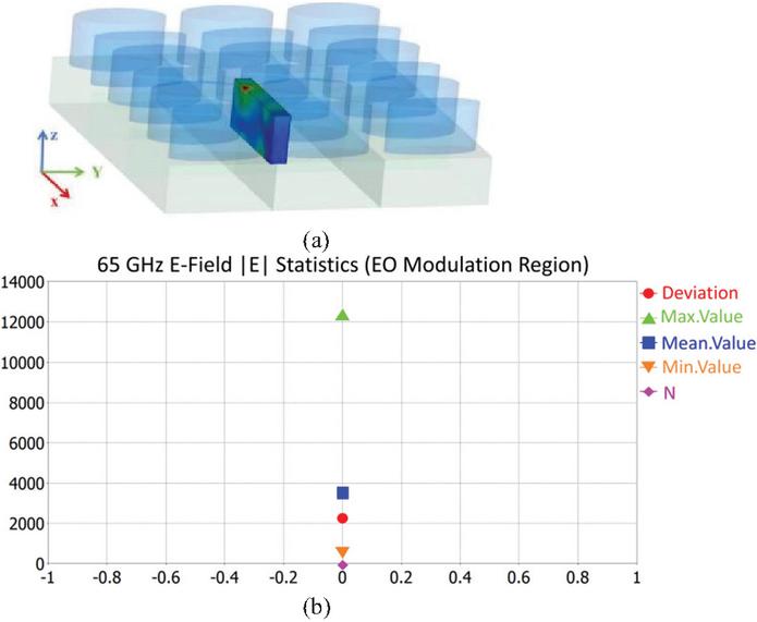
Figure 8 Volumetric statistical characteristics of electric field in EO interaction region at 65 GHz.
3.3 Electro-optic resonator configuration
The free spectral range (FSR) of the resonator is defined as the interval between the adjacent resonance peaks of the EO resonator, which can be calculated as [21]:
| (12) |
where is the radius of the EO resonator, is the speed of light, and is the refraction index of the EO resonator at the operation wavelength [21].
High-speed electro-optic modulation can be achieved only when the resonant frequency of the proposed dielectric metasurface matches FSR [23]. Therefore, the radius of the EO resonator is determined to be 0.34 mm for a resonant frequency of 65 GHz. As mentioned before, the electro-optic crystal is better located at the position where the maximum RF field occurs. However, for the convenience of processing, the electro-optic resonator is put at the top of the metasurface, which is close to the position of maximum electric field, as shown in Fig. 7. When the excitation electric field along the -axis is , the field-enhancement factor . The field-enhancement factor of 12 ensures the receiver’s high sensitivity, as further verified in section 5.
4 PARAMETRIC DISCUSSION
This section analyzes the effects of key parameters on transmission performance and the electric field distribution. Figure 9 shows the effect of the semi-minor axis of the cylinder when is 0.3255 mm. The is set to two values: and of b1, respectively, to observe the impact of asymmetry. Two resonant peaks can be seen when is extremely different from , shown as the solid line in Fig. 9. The first resonance point P1 is highly sensitive to , which indicates that the symmetry of the structure has a great influence on the resonant position and quality . Traditional dark mode is usually an array of perfectly symmetrical disks or rings in the all-dielectric metasurface based on the EIT, the metasurface structure is usually an array of perfectly symmetrical disks with same and . The resonance modes correspond to the circulation of electric and magnetic fields inside the cylinders. Only the dark mode can be excited by the resonance of the bright mode under the condition that the structure is asymmetric, which is an indirect excitation method. The structure’s symmetry is broken to allow the mode to leak out, enabling direct coupling with the external light field.

Figure 9 Transmission spectra for different asymmetry parameters (semi-minor axis length of the elliptical cylinder). P1 and P2 are the resonant peaks.
Figure 10 indicates the influence of the height of two elliptical cylinders and the substrate on the resonance. It can be seen that the two resonant frequencies are sensitive to the height . Both Fano resonant peaks shift to the right when decreases from 1.1358 mm to 1.014 mm. In addition, the height of the two ellipticals affects not only the resonant position but also the resonant intensity. Results show that optimal quality can be obtained by increasing . The slot formed by the two adjacent cylinders gives rise to the slot effect, further enhancing the near-field strength. The electric field loop inside the slot is squeezed and expanded along the -axis as the height increases. Even though the resonant quality improves with increasing height, the maximum electric field is located inside the cylinders and is not suitable for placing the electro-optic resonator.

Figure 10 Transmission spectra versus frequency for different heights of elliptical cylinders and substrates.

Figure 11 Transmission spectra versus frequency for different center-to-center distances between two elliptical cylinders.
Figure 11 shows the transmission coefficient and the distribution of the electric field for different intervals between two elliptical cylinders. The interval is 1.1049 mm and 1.4649 mm, respectively, due to the limitation of the periodic structure and the size of the elliptical cylinders. The spectra are nearly identical for and . This is because the sum of 1.1049 and 1.4649 mm is exactly the period of the structure . Since the unit cell is square and the metasurface is periodic, these two structures are identical. Since the sum of and 1.4649 mm equals the structural period , the two structures are equivalent in periodic metasurfaces, resulting in almost identical transmission spectra. This equivalence confirms that the metasurface’s periodicity, rather than the absolute spacing between cylinders within a single unit cell, is the key factor governing transmission performance.
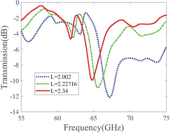
Figure 12 Transmission spectra versus length of elliptical cylinder.
The influence of the major axis on resonance is shown in Fig. 12. As increases from 2.002 mm to 2.34 mm, the resonant peak shifts to the left, and the quality factor decreases. This is because the loss of dielectric material increases with cylinder’s surface area.
Fano resonance modes are highly sensitive to structural parameters. The optimal resonant effect and minimized structure can be achieved by increasing the asymmetry of the two elliptical cylinders.
5 SENSITIVITY ANALYSIS
The demodulated RF power after photodetection varies with the power incident on the metasurface, which is determined by the power supplied to the horn antenna. When the power fed into the horn antenna and the distance from the horn antenna to the dielectric metasurface are given, the power impinging on the metasurface antenna can be calculated by a standard radiation model of the horn antenna [23]. Therefore, the relationship between the RF power after photodetection and the power impinging on the dielectric metasurface can be approximately fitted to experimental points obtained by varying the power fed into the horn antenna. When the RF power after photodetection equals the observed noise floor, the corresponding free-space power impinging on the metasurface antenna, namely the measured receiver sensitivity, can be obtained by the previously fitted linear relationship.
The theoretically detected RF power can be calculated [22]:
| (13) |
where is the modulation depth of the light in the EO resonator, is the photodetector responsivity, is the average optical power at the detector, and is the detector resistance.
On the basis of Equations (1), (2), (3), (4), and (13), the relationship between the theoretically detected RF power and the power impinging on the dielectric metasurface is linear:
| (14) |
The theoretical receiver sensitivity is defined as the power impinging on the dielectric metasurface when the detected RF power equals the noise floor, and it can be calculated using (14). For estimating the receiver sensitivity of our proposed system in practice, a coefficient of 0.01 is multiplied and, consequently, the estimated receiver sensitivity is:
| (15) |
Although the receiver sensitivity calculated by (15) is worse than that calculated by (14), this conservative estimation of performance considers the complexity of the whole receiver system and the influence of the actual environment, which provides a practical design margin in practical application and enables the proposed system to detect weaker incident power.
With fixed large/small resonator ratio , 1.00, 1.15, the effective aperture area is 0.957767, 1.325630, 1.753145 arb. unit, and the EO volume-averaged field is 2.6, 3.7, 4.8 (Fig. 13), numerically validating the monotonic aperture-sensitivity scaling.

Figure 13 EO volume-averaged field vs effective aperture area (.
It can be seen that the measured RF power after photodetection reported in other papers is about 20 dBm lower than the result calculated by (14), which verifies the rationality of setting the coefficient to 0.01 [13, 14, 15, 16, 17, 18, 19, 20, 21, 22, 23].
To calculate the system’s sensitivity, the effective permittivity of the metasurface must be determined. The textbook method relies on the refractive index and impedance . Permittivity can be calculated by . Since the metasurface is composed of various dielectric materials and the refractive index is complex; a practical method is adopted to obtain the refractive index and impedance using the reflection coefficient () and transmission coefficient (). The parameters related to refractive index and impedance are given by [31, 32, 33]:
| (16) | ||
| (17) |
where , means the thickness of the slab, and is the wave number of the incident wave in free space.
The refractive index and impedance can be calculated by:
| (18) | |
| (19) |
where is an integer related to the branch index of .
The detection bandwidth is set to 10 kHz, and other parameters of the proposed receiver used in the sensitivity analysis are as follows: , , , , , , , and . The linear relationship of the estimated receiver sensitivity and RF power after photodetection is shown in Fig. 14. According to detection of the free-space RF signal by the prototype receiver with and without the dielectric antenna, the observed noise floor generated by the RIN of the source laser is [13]. Therefore, the estimated receiver sensitivity of the proposed system, namely the incident RF power at which the RF power after photodetection equals the observed noise floor, is 52.1 dBm .

Figure 14 Estimated receiver sensitivity of the proposed metasurface receiver.
From (12) and (15), it can be concluded that receiver sensitivity will deteriorate when the radius and circumference of the EO resonator decrease as the frequency of the incident signal increases. However, the proposed receiver still exhibits excellent performance, with sensitivity below 50 dBm at the millimeter-wave band.
6 CONCLUSION
Metallic receiving antennas are inherently vulnerable to HEMP owing to their high electrical conductivity. All-dielectric antennas offer a promising alternative for radio front-end systems in HEMP-prone scenarios. In this paper, a new radio front-end receiver based on a metasurface operating in the millimeter-wave band is designed. By analyzing the influence of each structural parameter on Fano resonance, a metasurface antenna with a cell array was proposed, where the electric field enhancement around the structure at 65 GHz is achieved. The electro-optic resonator disk was placed at the maximum electric field position, and the receiver sensitivity was improved to 52 dBm. With a compact size of , the proposed metasurface enables 5G RF front-end systems to achieve HPMMW immunity. It should be noted that the current study is based on simulations and theoretical analyses, and the absence of experimental validation is a limitation that needs to be addressed. In future work, we plan to fabricate the prototype receiver and conduct experimental tests to verify its sensitivity, resonant characteristics, and HPMMW resistance, aiming to provide more solid support for practical applications.
ACKNOWLEDGMENT
This work was supported by the Beijing Municipal Natural Science Foundation (L233017), the National Key Laboratory of Intelligent Coal Mining and Strata Control (SKLIS202407), and the MIIT Key Laboratory of Radio Spectrum Monitoring Technology (SRTC-KFKT202501).
REFERENCES
[1] I. V. Mikhelson, S. Bakhtiari, T. W. Elmer, and A. V. Sahakian, “Remote sensing of heart rate and patterns of respiration on a stationary subject using 94-GHz millimeter-wave interferometry,” IEEE Transactions on Biomedical Engineering, vol. 58, no. 6, pp. 1671–1677, 2011.
[2] R. Appleby and R. N. Anderton, “Millimeter-wave and submillimeter-wave imaging for security and surveillance,” Proceedings of the IEEE, vol. 95, no. 8, pp. 1683–1690, 2007.
[3] S. Hantscher, M. Hagelen, S. Lang, H. Essen, M. Wieneke, W. Koch, and A. Tessmann, “Security assistant system combining millimeter wave radar sensors and chemical sensors,” in 2011 IEEE International Symposium on Antennas and Propagation (APSURSI), IEEE, pp. 216–219, 2011.
[4] M. Field, T. Kimura, J. Atkinson, D. Gamzina, N. C. Luhmann, B. Stockwell, T. J. Grant, Z. Griffith, R. Borwick, C. Hillman, B. Brar, T. Reed, M. Rodwell, Y.-M. Shin, L. R. Barnett, A. Baig, B. Popovic, C. Domier, R. Barchfield, J. Zhao, J. A. Higgins, and Y. Goren, “Development of a 100-W 200-GHz high bandwidth millimeter-wave amplifier,” IEEE Transactions on Electron Devices, vol. 65, no. 6, pp. 2122–2128, 2018.
[5] H. Yin, L. Zhang, J. Xie, K. Ronald, W. He, G. Shu, J. Zhao, Y. Yin, X. Chen, Y. Alfadhl, A. Cross, and A. Phelps, “Compact high-power millimeter wave sources driven by pseudospark-sourced electron beams,” IET Microwaves, Antennas & Propagation, vol. 13, no. 11, pp. 1794–1798, 2019.
[6] J. Curtis, H. Zhou, and F. Aryanfar, “A fully integrated Ka-band front-end for 5G transceiver,” in 2016 IEEE MTT-S International Microwave Symposium (IMS), IEEE, pp. 1–3, 2016.
[7] M. K. Hedayati, A. Abdipour, R. S. Shirazi, M. J. Ammann, M. John, C. Cetintepe, and R. B. Staszewski, “Challenges in on-chip antenna design and integration with RF receiver front-end circuitry in nanoscale CMOS for 5G communication systems,” IEEE Access, vol. 7, pp. 43190–43204, 2019.
[8] W. Radasky, “Protection of commercial installations from the high-frequency electromagnetic threats of HEMP and IEMI using IEC standards,” in 2010 Asia-Pacific International Symposium on Electromagnetic Compatibility, IEEE, pp. 758–761, 2010.
[9] J.-H. Lee, J.-H. Cho, and E.-J. Kim, “Analysis of HEMP coupling signal for a coaxial cable with braided shields,” The Journal of Korean Institute of Electromagnetic Engineering and Science, vol. 22, no. 8, pp. 790–796, 2011.
[10] E. Easton, K. Bryant, and W. Radasky, “Testing of a module for electrical substations to demonstrate HEMP and IEMI protection and GIC detection,” in 2020 IEEE International Symposium on Electromagnetic Compatibility & Signal/Power Integrity (EMCSI), IEEE, pp. 442–447, 2020.
[11] R. Hao, X. Zhang, H. Gao, H. Wu, J. Cheng, and G.-P. Li, “A novel high-altitude electromagnetic pulse (HEMP) protection circuit for RF applications,” Microelectronics Journal, vol. 84, pp. 1–8, 2019.
[12] H. Shin, N. Heo, J. Park, I. Seo, and J. Yoo, “All-dielectric structure development for electromagnetic wave shielding using a systematic design approach,” Applied Physics Letters, vol. 110, no. 2, p. 021908, 2017.
[13] R. C. Hsu, A. Ayazi, B. Houshmand, and B. Jalali, “All-dielectric photonic-assisted radio front-end technology,” Nature Photonics, vol. 1, no. 9, pp. 535–538, 2007.
[14] J. Nasir, M. H. Jamaluddin, M. Khalily, M. R. Kamarudin, and I. Ullah, “Design of a MIMO dielectric resonator antenna for 4G applications,” Wireless Personal Communications, vol. 88, no. 3, pp. 525–536, 2016.
[15] H. Yang, Z. Guo, X. Li, Y. Zhang, X. Song, and S. Wang, “A compact circularly polarized crossed dipole antenna with wide bandwidth using split ring resonator and parasitic patches,” Applied Computational Electromagnetics Society (ACES) Journal, vol. 39, no. 1, pp. 1–10, 2024.
[16] J.-X. Chen, H.-T. Xing, J.-M. Huang, M.-N. Wang, and Z.-H. Ma, “A three-dimensional compact propeller-shaped circularly polarized ceiling antenna,” Applied Computational Electromagnetics Society (ACES) Journal, vol. 39, no. 1, pp. 1–10, 2024.
[17] D. L. Marks, O. Yurduseven, and D. R. Smith, “Cavity-backed meta-surface antennas and their application to frequency diversity imaging,” JOSA A, vol. 34, no. 4, pp. 472–480, 2017.
[18] Z. Li, M.-H. Kim, C. Wang, Z. Han, S. Shrestha, A. C. Overvig, M. Lu, A. M. Agarwal, M. Loncar, D. R. Smith, and N. Yu, “Controlling propagation and coupling of waveguide modes using phase-gradient metasurfaces,” Nature Nanotechnology, vol. 12, no. 7, p. 675, 2017.
[19] F. Lotti, A. Mirzaei, A. E. Miroshnichenko, and A. V. Zayats, “Nanoparticle-based metasurfaces for angular independent spectral filtering applications,” Journal of Applied Physics, vol. 126, no. 21, p. 213101, 2019.
[20] L.-H. Gao, Q. Cheng, J. Yang, S.-J. Ma, J. Zhao, S. Liu, H.-B. Chen, Q. He, W.-X. Jiang, H.-F. Ma, Q.-Y. Wen, L.-J. Liang, B.-B. Jin, W.-W. Liu, L. Zhou, J.-Q. Yao, P.-H. Wu, and T.-J. Cui, “Broadband diffusion of terahertz waves by multi-bit coding metasurfaces,” Light: Science & Applications, vol. 4, no. 9, pp. e324–e324, 2015.
[21] D. Cohen and A. Levi, “Microphotonic components for a millimeter-wave receiver,” Solid-State Electronics, vol. 45, no. 3, pp. 495–505, 2001.
[22] B. Jalali, A. Ayazi, R. C. Hsu, A. Yick, W. H. Steier, and G. Betts, “A nonelectronic wireless receiver with immunity to damage by electromagnetic pulses,” Practical Applications of Microresonators in Optics and Photonics, Boca Raton, FL: CRC Press, pp. 433–458, 2009.
[23] R. C. Hsu, A. Ayazi, B. Houshmand, and B. Jalali, “All-dielectric wireless receiver,” in 2007 IEEE/MTT-S International Microwave Symposium, IEEE, pp. 221–224, 2007.
[24] M. F. Limonov, M. V. Rybin, A. N. Poddubny, and Y. S. Kivshar, “Fano resonances in photonics,” Nature Photonics, vol. 11, no. 9, pp. 543–554, 2017.
[25] W. Wang, L. Zheng, L. Xiong, J. Qi, and B. Li, “High Q-factor multiple Fano resonances for high-sensitivity sensing in all-dielectric metamaterials,” OSA Continuum, vol. 2, no. 10, pp. 2818–2825, 2019.
[26] J. Leng, J. Peng, A. Jin, D. Cao, D. Liu, X. He, F. Lin, and F. Liu, “Investigation of terahertz high Q-factor of all-dielectric metamaterials,” Optics & Laser Technology, vol. 146, p. 107570, 2022.
[27] H. Li, Y. Zhang, M. Qin, L. Wang, and Y. Chai, “High-quality Fano resonances and multispectral perfect absorption in mushroom-type dielectric metamaterials with a silver nanofilm,” EPL (Europhysics Letters), vol. 133, no. 6, p. 67002, 2021.
[28] Y. S. Joe, A. M. Satanin, and C. S. Kim, “Classical analogy of Fano resonances,” Physica Scripta, vol. 74, no. 2, p. 259, 2006.
[29] Z. Chen, S. Zhang, Y. Chen, Y. Liu, P. Li, Z. Wang, X. Zhu, K. Bi, and H. Duan, “Double Fano resonances in hybrid disk/rod artificial plasmonic molecules based on dipole-quadrupole coupling,” Nanoscale, vol. 12, no. 17, pp. 9776–9785, 2020.
[30] W. Wang, Y. Jin, W. Wang, B. Bonello, B. Djafari-Rouhani, and R. Fleury, “Robust Fano resonance in a topological mechanical beam,” Physical Review B, vol. 101, no. 2, p. 024101, 2020.
[31] J. A. Kong, Theory of Electromagnetic Waves. New York: Wiley-Interscience, 1975.
[32] A. Nicolson and G. Ross, “Measurement of the intrinsic properties of materials by time-domain techniques,” IEEE Transactions on Instrumentation and Measurement, vol. 19, no. 4, pp. 377–382, 1970.
[33] W.-C. Wang, Electromagnetic Wave Theory, ME557 Course Material, University of Washington, 1986.
BIOGRAPHIES

Qiwei Liu received the master’s degree in business administration from the Central University of Finance and Economics, Beijing, China, in 2019. He is currently working toward the Ph.D. degree in electronic engineering at the Beijing University of Posts and Telecommunications, Beijing, China. His research interests include electromagnetic compatibility, integrated circuits, ray tracing, and machine learning.

Dan Shi (Member, IEEE) received the Ph.D. degree in electronic engineering from the Beijing University of Posts & Telecommunications, Beijing, China, in 2008. She is a Professor with Beijing University of Posts & Telecommunications. Her interests include electromagnetic compatibility, electromagnetic environment, and electromagnetic computation.

Yanchi Liu received the bachelor’s degree in e-commerce and law in 2023 from the Beijing University of Posts & Telecommunications, Beijing, China, where she is currently working toward the doctor’s degree in electronic engineering. Her research interests include electromagnetic compatibility, intelligent design, and machine learning.

Jintao He received the bachelor’s degree in communications engineering from Xi’an University of Posts & Telecommunications, Xi’an, China, in 2024. He is currently working toward the Doctor’s degree in electronic engineering from the Beijing University of Posts & Telecommunications, Beijing, China. His research interests include electromagnetic compatibility and machine learning.

Hongbo Tao received the Ph.D. degree in electronic engineering from Beijing University of Posts and Telecommunications, Beijing, China, in 2003. Currently, he works at the National Radio Monitoring Center. His research interests include radio detection technology, electromagnetic compatibility analysis, and specialized radio measuring instruments.

Xiaoyong Liu received the bachelor’s degree in radio technology and information system from Tsinghua University, Beijing, China, in 2002. He is currently working toward the doctoral degree in electronic science and technology with the Beijing University of Posts and Telecommunications, Beijing, China. His research interests include electromagnetic compatibility, testing and measurement, and radio frequency spectrum technology.

Zhonghua Xin received the master degree from Beijing Technology and Business University, Beijing, China, in 2002. She is a senior engineer with the Coal Science and Technology Research Institute. Her research interests include electromagnetic compatibility of Mining electrical equipment and wireless equipment, electromagnetic environment of underground coal mine.

Yuhao Jia received the bachelor’s degree in information and computing science from Beihang University, Beijing, China, in 2020, and the master’s degree in electronic information engineering from City University of Hong Kong, Hong Kong, China, in 2023. He is currently a researcher with China Coal Research Institute (CCRI), Beijing, China. His research interests include intelligent detection technology and electromagnetic compatibility.
ACES JOURNAL, Vol. 41, No. 4, 323–333
DOI: 10.13052/2026.ACES.J.410404
© 2025 River Publishers