Gain-Focusing Performance Evaluation of Nonlinear Frequency Diverse Arrays
Xin Wang1, Tao Jiang1*, Chengkai He1, and Gengzuo Liu2
1College of Information and Communication Engineering Harbin Engineering University, Harbin, 150001, China wangxin98@hrbeu.edu.cn, jiangtao@hrbeu.edu.cn, hechengkai@hrbeu.edu.cn
∗Corresponding Author
2College of Nuclear Science and Technology Harbin Engineering University, Harbin, 150001, China liugengzuo@hrbeu.edu.cn
Submitted On: December 03, 2025; Accepted On: May 04, 2026
ABSTRACT
Nonlinear frequency diverse arrays have attracted increasing attention because of their unique point-like focusing characteristics in the joint angle-range domain. However, the quantitative relationship between the focusing pattern and key design parameters, as well as systematic performance evaluation tools, have not been fully established. In this paper, we propose the gain-focusing area as a quantitative metric for assessing the focusing efficiency of nonlinear frequency diverse arrays (NFDA). Unlike conventional one-dimensional beamwidth measures, the gain-focusing area captures the joint angle-range behavior of the array and provides a basis for performance evaluation and design optimization. Using this metric, we systematically study single- and dual-region focusing, and quantify the influence of focusing location (angle, range) and array design parameters (number of elements, frequency-offset coefficient) on the gain-focusing performance. Numerical simulations demonstrate that the proposed gain-focusing-area based evaluation method provides a more reliable performance metric; compared with existing approaches, it nearly doubles the valid angular range while maintaining accurate characterization of the focusing behavior. This enables NFDA spatial focusing capability and parameter sensitivity to be robustly quantified over a wider field of view, offering a more dependable tool for shaping the electromagnetic environment in and around the target region.
Keywords: Gain-focusing area, nonlinear frequency diverse array, single-point focusing, two-point focusing..
1 INTRODUCTION
In array signal processing, nonlinear frequency diverse arrays (NFDA) achieve two-dimensional beam steering over angle and range, concentrating gain at the prescribed target while decreasing gain as the angular or range offset increases. This behavior enables flexible and highly controllable gain focusing at the target location [1, 2], which is valuable for radar detection and wireless communications because it reduces electromagnetic impact around the target area [3, 4]. By incorporating nonlinear frequency offset coefficients, NFDA mitigates the intrinsic “S-shaped” coupling between angle and range observed in linear frequency diverse arrays, thereby forming focal regions at specific spatial locations [5, 6, 7, 8]. A variety of optimization approaches, genetic, artificial bee colony, and mayfly algorithms, have been employed to tune these coefficients and obtain narrower beam widths with reduced peak sidelobe ratios [9, 10, 11, 12, 13, 14, 15].
Among the existing studies, [16] provides a representative analysis related to NFDA focusing behavior. However, its analytical derivation is established under the approximation conditions specified in that work and is mainly oriented to a THz near-field scenario. In contrast, the present work considers a beampattern-based geometric evaluation framework for far-field NFDA gain focusing.
To address this gap, this paper introduces the gain-focusing area as a quantitative metric for far-field NFDA focusing in the joint angle-range domain, and further establishes a corresponding geometric calculation framework for its extraction and evaluation. Based on 3 dB boundary extraction and equivalent tilted-ellipse characterization, the proposed framework enables reproducible computation of , and . Using this framework, we study both single-point and two-point gain focusing and systematically quantify the effects of target location and array design parameters.
2 GAIN-FOCUSING AREA DEFINITION AND CALCULATION FRAMEWORK
In contrast to traditional phased arrays, NFDAs can focus the gain not only in the angular dimension but also in the range dimension, thereby exhibiting inherently two-dimensional gain-focusing behavior. To characterize this behavior in a quantitative and reproducible manner, this work not only defines the gain-focusing area as a performance metric, but also establishes a geometric calculation framework for its extraction in the angle-range plane. Specifically, the proposed framework identifies the 3 dB focusing boundary from the far-field NFDA beampattern, constructs an equivalent tilted elliptical focusing region, and computes its area as .
In this work, the two-dimensional gain-focusing area is calculated directly from the NFDA far-field beampattern in the joint angle-range domain. The proposed approach is based on 3 dB boundary extraction and geometric characterization of the focusing region, and therefore does not rely on a specific closed-form analytical approximation. For reference, [16] considers a different derivation route under its own approximation conditions.
Let denote the normalized NFDA beampattern in the selected angle-range observation plane, where and represent the range and angular coordinates in that plane, respectively, denotes the transmit frequency corresponding to the -th array element, and is the element index. Since the present work focuses on a two-dimensional gain-focusing analysis for a linear NFDA in the chosen observation plane, the out-of-plane angular variable is not introduced in the current formulation. Its maximum at the target location is
| (1) |
where , is the reference carrier frequency and is the nonlinear frequency offset of the -th element.
The gain-focusing region is then defined as
| (2) |
and the gain-focusing area is defined as the geometric area of this region,
| (3) |
In computation, is evaluated on a discrete angle-range grid, and all points satisfying (2) are extracted as the 3 dB gain-focusing region. is then estimated from this region using the geometric procedure in Fig. 2. Under the considered settings, is mainly influenced by the target position, frequency-offset coefficient, and array size.
Equations (1)–(3) define the gain-focusing area metric, whereas the practical computation of is carried out through the calculation framework summarized in Fig. 1 and detailed in Steps (1)–(6). Under the NFDA configuration considered in this paper, the size of is primarily governed by the target position, the frequency-offset coefficient, and the number of array elements.
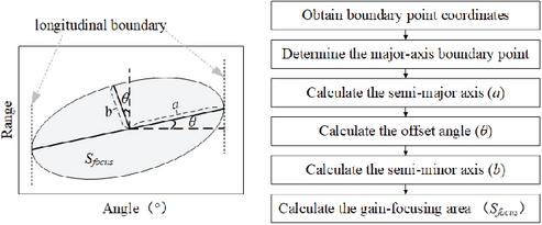
Figure 1 Flowchart of the proposed gain-focusing area calculation framework and the specific calculation steps.
For the configurations considered here, the 3 dB region is well approximated by a tilted ellipse [16]. Therefore, is obtained by determining the semi-major axis, semi-minor axis, and offset angle of the equivalent ellipse from the boundary points, following Steps (1)–(6) in Fig. 1.
(1) Extract the 3 dB boundary points from the simulated beampattern in the angle-range plane.
(2) Determine the major-axis boundary point by finding the boundary point with the largest angular extent and its range coordinate.
(3) Calculate the semi-major axis and the offset angle from the target point and the major-axis boundary point.
(4) Determine the short-axis boundary point from the target coordinates and the offset angle .
(5) Calculate the semi-minor axis from the target point and the short-axis boundary point.
(6) Compute from the semi-major axis and semi-minor axis .
Table 1 , and for different target positions
| Focus Target Positions | of Ours | of [14] | ||
| (0∘, 80 km) | 7.3 | 4.3 | 23.7596 | 316.4782 |
| (0∘, 20 km) | 7.3 | 4.3 | 23.7596 | 316.4782 |
| (0∘, 50 km) | 7.3 | 4.3 | 23.7596 | 316.4782 |
| (10∘, 50 km) | 7.5 | 4.3 | 24.4191 | 377.1766 |
| (10∘, 50 km) | 7.5 | 4.3 | 24.4191 | 377.1766 |
| (20∘, 50 km) | 7.8 | 4.3 | 25.4083 | 775.5258 |
| (20∘, 50 km) | 7.8 | 4.3 | 25.4083 | 775.5258 |
| (30∘, 50 km) | 8.5 | 4.3 | 27.7167 | 2.0517e3 |
| (30∘, 50 km) | 8.5 | 4.3 | 27.7167 | 2.0517e3 |
| (40∘, 50 km) | 9.6 | 4.3 | 31.3413 | 474.5241 |
| (40∘, 50 km) | 9.6 | 4.3 | 31.3413 | 474.5241 |
| (50∘, 50 km) | 11.6 | 4.3 | 37.9405 | 327.9682 |
| (50∘, 50 km) | 11.6 | 4.3 | 37.9405 | 327.9682 |
| (60∘, 50 km) | 15.1 | 4.3 | 49.4845 | 332.2909 |
| (60∘, 50 km) | 15.1 | 4.3 | 49.4845 | 332.2909 |
Based on this definition, is computed from the extracted 3 dB gain-focusing region and then used as a quantitative metric in the subsequent single-point and two-point performance evaluations.
3 SINGLE POINT GAIN-FOCUSING PERFORMANCE ANALYSIS
To investigate the focusing performance of NFDAs, we examine the factors influencing from two perspectives.
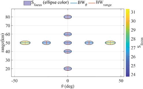
Figure 2 Impact of target position on gain-focusing area.
3.1 The influence of target position on gain-focusing area
The changes in gain-focusing area are examined by independently varying the target position along the angle and range dimensions. To assess the impact of these parameters, we simulate NFDA patterns for targets at a fixed range with different angles and at a fixed angle with different ranges. Figure 2 depicts, for both cases, the NFDA focusing points together with each point’s and 3 dB widths— (horizontal) and (vertical). Note that Fig. 2 does not display the numerical values of the angular offsets; it only visualizes the focusing points and widths. The corresponding quantitative data, including , , and for each target position, are provided in Table 1.
As shown in Fig. 2 and Table 1, varying the target range while keeping the angle fixed leaves , , and almost unchanged, indicating that, in our simulations, the target range has little influence on the gain-focusing performance. In contrast, as observed in Fig. 2 and the corresponding data in Table 1, varying the target position at a fixed range but different angles results in a minimum when the target is aligned with the array’s normal direction. Similarly, from a one-dimensional perspective, remains constant, while is minimized when there is no angular offset between the target and the array, indicating that gain-focusing width in the angle dimension is minimized at this position.
The numerical variation trends of , and with respect to target angle are consistent with the expected focusing behavior, which also supports the validity of the proposed evaluation framework. As a representative reference, [16] reports similar variation tendencies under its own assumptions. However, since the present method is based on direct geometric extraction from the obtained beampattern, it can be applied in the far-field NFDA configurations considered here over a wider angular range.
3.2 Impact of array parameters on gain-focusing area
From equations (1)–(3), depends on the underlying beampattern , which in turn is determined by the array size and the frequency-offset coefficient. We therefore numerically examine in this section, we vary these parameters and examine the changes in gain-focusing width in the angle and range dimensions. Figure 3 shows how NFDA , , and vary under different array sizes and frequency offset coefficients, and provides the corresponding values of , , and .
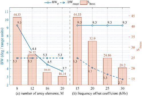
Figure 3 Impact of array parameters on gain-focusing area.
As shown in Fig. 3 (according to the data therein), decreases as the number of array elements increases, indicating that more elements yield a smaller gain-focusing area. In parallel, the angular gain-focusing width exhibits a substantial reduction, whereas the range-dimension width remains nearly invariant, suggesting that the element number primarily affects the angular width. According to Fig. 3, also decreases as the frequency-offset coefficient increases. At the target position, remains essentially constant, while decreases significantly, implying that a larger frequency-offset coefficient produces a narrower range-dimension focusing width and a more concentrated focus.
In conclusion, for the far-field configurations considered here, the target range has a negligible influence on . In contrast, the target angle and the array design parameters (number of elements and frequency-offset coefficient) strongly affect the gain-focusing area and its one-dimensional widths. The angle parameters of the target position affect the gain-focusing area, with the minimum gain-focusing area occurring when the target is aligned with the normal direction of the array. Additionally, for NFDA, an increase in the number of array elements or the frequency offset coefficient results in a reduction in the gain-focusing area. From a one-dimensional perspective, the range parameters do not affect either or . In contrast, the angle of the target and the number of elements primarily affect , with negligible influence on in the considered configurations, whereas the frequency-offset coefficient mainly affects , with remaining nearly unchanged. Thus, the gain-focusing area is primarily governed by the angular position and array design parameters, while the effect of target range on is negligible in the far-field configurations examined.
Furthermore, simulation results show that NFDA forms a focused gain-focusing area solely at the target position, with a controllable gain-focusing area. The array gain outside this area remains low, suggesting that, in the considered scenarios, NFDA-based focusing may help reduce the electromagnetic impact around the target region compared with conventional beamforming.
4 TWO POINT GAIN-FOCUSING PERFORMANCE ANALYSIS
Assuming the target positions are set at (40∘, 60 km) and (50∘, 30 km), the simulation results indicate that NFDA can generate two distinct gain-focusing areas with controllable positions, as shown in Fig. 4.
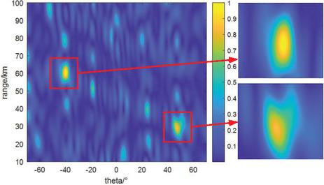
Figure 4 NFDA beam pattern.
To further analyze the two-point gain-focusing performance of NFDA, simulations were conducted to examine the changes in within each focusing area under varying conditions, such as changes in target positions and modifications to array parameters.
4.1 Impact of changes in target position on gain-focusing area
Alterations in the gain-focusing area of the two focusing regions are examined by varying the range and angle of the target positions. Table 2 reports simulations for both cases, targets with identical angles but different ranges, and targets with identical ranges but different angles.
Table 2 for two-target configurations
| Target Location | Target Location | |||
| A | , 15 km) | , 60 km) | ||
| B | , 20 km) | , 70 km) | ||
| C | , 15 km) | , 60 km) | ||
| D | , 20 km) | , 70 km) |
Four representative two-target configurations (A–D) are considered, as summarized in Table 2. In either case the simulated gain-focusing areas successfully encompass both target positions. Cases A/B and cases C/D correspond to two targets sharing the same angle but different ranges, whereas cases A/C and cases B/D correspond to two targets sharing the same range but different angles. According to the data in Table 2, changing either the angle or the range modifies each focusing area. For the limited configurations examined, these variations do not follow a simple monotonic trend, suggesting that the two-point focusing behavior is jointly shaped by the relative positions of the two targets and the NFDA design parameters.
4.2 Impact of variations in array parameters on gain-focusing area
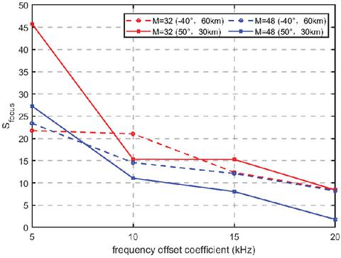
Figure 5 of each focusing region.
As shown in Fig. 5, the gain-focusing area in each region decreases as the number of array elements increases, consistent with single-point focusing. Notably, although both regions shrink, the focusing area at (40∘, 60 km) remains consistently smaller than that at (50∘, 30 km). Likewise, Fig. 5 shows that as the frequency offset coefficient increases, the gain-focusing area of each focusing region gradually decreases, again aligning with single-point NFDA behavior; however, the two areas remain unequal.
These findings indicate that the nonlinear frequency diverse array can realize two-point gain-focusing for targets at different positions. By increasing the number of array elements or adjusting the frequency offset coefficient, the gain-focusing area can be reduced so that array gain concentrates on the targets while the electromagnetic influence outside the focus is strongly attenuated.
5 CONCLUSION
This paper addresses the characterization of NFDA gain-focusing by introducing the gain-focusing area as an effective quantitative metric for point-like focusing. Using this metric, we analyze one- and two-region gain-focusing and quantify the effects of focusing location (angle, range) and design parameters (number of array elements, frequency offset coefficient). Numerical simulations confirm the spatial localization capability, parameter sensitivity, and the improved reliability of the proposed metric; compared with existing approaches, it nearly doubles the valid angular range while maintaining accurate characterization of the focusing behavior. Guided by this metric, NFDAs can be tuned to meet specific requirements, allowing gain-focusing regions to cover target locations accurately over a wider field of view. This adaptability is promising for applications such as fixed-point communications and the mitigation of electromagnetic radiation hazards.
ACKNOWLEDGMENT
This work is supported by the Key Laboratory of Advanced Marine Communication and Information Technology, Ministry of Industry and Information Technology, Harbin Engineering University, Harbin, China.
REFERENCES
[1] P. Antonik, M. Wicks, H. Griffiths, and C. J. Baker, “Frequency diverse array radars,” 2006 IEEE Conference on Radar, p. 3, 2006.
[2] G. H. Zeng, Y. Liao, J. Wang, and Y. C. Liang, “Design of a chaotic index modulation aided frequency diverse array scheme for directional modulation,” IEEE Transactions on Vehicular Technology, vol. 72, no. 8, pp. 10965–10970, 2023.
[3] Y. Mo, X. J. Xi, L. Chen, W. J. Wu, and D. D. Wang, “Analysis of influence of FSS radome on array antenna scanning,” Chinese Journal of Ship Research, vol. 15, no. 2, pp. 31–35, 2020.
[4] M. Xiao, T. Hu, X. Shao, L. Wu, and Z. Xiao, “A single-snapshot robust beamforming for FDA-MIMO radar based on AID3,” IEEE Transactions on Vehicular Technology, vol. 74, no. 1, pp. 38–49, 2025.
[5] W. Khan, I. M. Qureshi, A. Basit, and B. Shoaib, “Transmit/received beamforming for MIMO log-frequency diverse array radar,” in 2016 13th International Bhurban Conference on Applied Sciences and Technology (IBCAST), pp. 689–693, 2016.
[6] X. Wang and T. Jiang, “Research on nonlinear UAV airborne frequency diverse array radar,” in 2023 International Conference on Microwave and Millimeter Wave Technology (ICMMT), pp. 1–3, 2023.
[7] H. Shao, J. Dai, J. Xiong, H. Chen, and W. Q. Wang, “Dot-shaped range-angle beampattern synthesis for frequency diverse array,” IEEE Antennas and Wireless Propagation Letters, vol. 15, pp. 1703–1706, 2016.
[8] Y. Ma, P. Wei, H. Zhang, and H. Liao, “A novel non-optimized method to synthesize dot-shaped range-angle beampattern for FDA,” in 2018 IEEE Radar Conference (RadarConf18), pp. 0781–0785, 2018.
[9] C. Cui, X. Ye, W. Li, and X. Shi, “Decoupled range-angle beampattern synthesis of frequency diverse array using genetic algorithm,” in 2017 Sixth Asia-Pacific Conference on Antennas and Propagation (APCAP), pp. 1–3, 2017.
[10] I. Aryanian, A. Abdipour, and G. Moradi, “Nonlinear analysis and performance improvement of amplifying aperture coupled reflectarray antenna,” Applied Computational Electromagnetics Society (ACES) Journal, vol. 31, no. 10, pp. 1164–1169, 2021.
[11] H. S. J. Xiong, W. Q. Wang, and H. Chen, “Frequency diverse array transmit beampattern optimization with genetic algorithm,” IEEE Antennas and Wireless Propagation Letter, vol. 16, pp. 469–472, 2017.
[12] Z. N. Jiang, Y. Zheng, X. F. Xuan, and N. Y. Nie, “A novel ultra-wideband wide-angle scanning sparse array antenna using genetic algorithm,” Applied Computational Electromagnetics Society (ACES) Journal, vol. 38, no. 2, pp. 100–108, 2023.
[13] A.M. Yao, W. Wu, and D.G. Fang, “Frequency diverse array antenna using time-modulated optimized frequency offset to obtain time-invariant spatial fine focusing beampattern,” IEEE Transactions on Antennas and Propagation, vol. 64, no. 10, pp. 4434–4446, 2016.
[14] E. Kurt, S. Basbug, and K. Guney, “Linear antenna array synthesis by modified seagull optimization algorithm,” Applied Computational Electromagnetics Society (ACES) Journal, vol. 36, no. 22, pp. 1552–1562, 2022.
[15] M. X. Xiao, T. Y. Hu, L. Li, X. L. Shao, J. Y. Zhang, and W. Xue, “Frequency diverse array beampattern synthesis with joint optimization of frequency offset and carrier,” in 2022 International Conference on Microwave and Millimeter Wave Technology (ICMMT), pp. 1–3, 2022.
[16] L. Li, H. Li, Z. Chen, W. Chen, and S. Li, “An analytical range-angle dependent beam focusing model for terahertz linear antenna array,” IEEE Wireless Communications Letters, vol. 11, no. 9, pp. 1870–1874, 2022.
BIOGRAPHIES

Xin Wang was born in 1998. She obtained the B.S. degree from Northeast Electric Power University, Jilin, China, in 2020. She is currently pursuing the Ph.D. degree in information and communication engineering at Harbin Engineering University. Her main research interests include array signal processing.

Tao Jiang (Member, IEEE) received the Ph.D. degree from Harbin Engineering University, Harbin, China, in 2002. Since 1994, he has been a Faculty Member of the College of Information and Communication, Harbin Engineering University, where he is currently a Professor. He was a Postdoctoral Researcher with the Research Institute of Telecommunication, Harbin Institute of Technology, Harbin, from 2002 to 2003, and a Visiting Scholar with the Radar Signal Processing Laboratory, the National University of Singapore, from 2003 to 2004. His current research interests include radio wave propagation, electromagnetic modeling and prediction, and electromagnetic environment.

Chengkai He was born in 2000. He obtained the B.S. degree from Harbin Engineering University, Harbin, China, in 2022. He is currently pursuing a master’s degree in Information and Communication Engineering at Harbin Engineering University, with a primary research focus on antennas.

Gengzuo Liu is a second-year Ph.D. student in Nuclear Science and Technology at Harbin Engineering University, China. His research spans radiation detection and protection, nuclear medical physics (FLASH-RT, BNCT), and accelerator beam/beamline design, employing machine learning and multiobjective optimization for fast gamma-ray buildup factor prediction and space-reactor design.
ACES JOURNAL, Vol. 41, No. 4, 361–366
DOI: 10.13052/2026.ACES.J.410408
© 2025 River Publishers