An Efficient MMA-PMA-CBFM for Solving Partial Modification Electromagnetic Scattering Problems
Ziang Shen1*, Xiaoxing Fang2, Xinlei Chen1, and Zhuo Li1
1College of Electronic and Information Engineering Nanjing University of Aeronautics and Astronautics, Nanjing 211106, China
shenziang@nuaa.edu.cn, chenxl@nuaa.edu.cn, lizhuo@nuaa.edu.cn
2School of Electronics and Information Engineering Nanjing University of Information Science and Technology, Nanjing 210044, China
fang_xiaoxing@nuist.edu.cn
*Corresponding author
Submitted On: December 05, 2025
Accepted On: June 23, 2026
ABSTRACT
This paper proposes an efficient algorithm for analyzing electrically large targets after partial modification. After solving the original model using the characteristic basis function method (CBFM), the mesh modification algorithm (MMA) is employed to modify the mesh according to requirements. Subsequently, in the CBFM blocks, only the characteristic basis functions (CBFs) associated with the affected blocks need to be regenerated, and the corresponding data in the reduced matrix are updated to rapidly obtain the solution of the new model by using the partial modification algorithm (PMA). Numerical examples validate the accuracy and efficiency of the proposed method, demonstrating its potential for practical engineering applications.
Keywords: Characteristic basis function method (CBFM), mesh modification algorithm (MMA), partial modification algorithm (PMA)..
1 INTRODUCTION
The characteristic basis function method (CBFM) [1, 2, 3] was proposed to reduce the number of unknowns and the matrix size in the traditional method of moments (MoM) [4, 5], thereby overcoming the high memory and computational complexity of MoM when analyzing electrically large targets. The characteristic basis functions (CBFs) in CBFM are not only significantly fewer in number compared to Rao-Wilton-Glisson (RWG) basis functions, but can also be combined with various acceleration algorithms such as adaptive cross approximation (ACA) [6, 7], further reducing the computational resources and enhancing the efficiency. However, in engineering applications, such as optimizing the layout of array antennas, engineers frequently encounter situations where the partial structures need to be modified repeatedly. The process of remeshing, regenerating CBFs, refilling, and resolving the reduced matrix after each partial modification remains very time-consuming.
To address the challenges of “partial modification problems,” researchers first proposed an “add-on” technique [8, 9] based on the partitioned-inverse formula and the Sherman-Morrison-Woodbury (SMW) formula [10, 11]. Although this technique is limited to adding small structures, it enables the data of unmodified regions to be reused, making the computational cost of the new structure almost negligible. Then, a partial modification algorithm (PMA) [12] was proposed to support more general partial modification operations based on data reuse, including adding, deleting, and modifying partial structure. Subsequently, a mesh modification algorithm (MMA) and the integral equation discontinuous Galerkin (IEDG) method [13, 14] was integrated into PMA [15], enabling mesh modifications during program execution. However, the above methods share a common bottleneck that they all require storing the impedance matrix of the original structure, and the storage complexity of MoM limits the scale of the problem to be solved. Given that add-on technique has already been introduced into CBFM [16], using PMA to reuse the reduced matrix data of CBFM provides an excellent solution for the partial modification of electrically large targets.
This paper proposes the MMA-PMA-CBFM that introduce the PMA [12] with the MMA [15] into the CBFM. First, after solving the original model, block division and CBFs of unaffected blocks are preserved, and then the reduced matrix equation and its solution are updated via the PMA [12]. Second, the MMA [15] is applied, which supports mesh modification of arbitrary shapes through a mesh-based representation and overlap detection, thereby reducing reliance on preprocessing software. Consequently, the MMA-PMA-CBFM reduces memory and computational cost while enabling automatic mesh modifications and rapid resolving of electrically large targets after partial modifications.
2 METHOD AND FORMULATIONS
2.1 Conventional CBFM
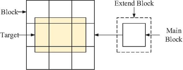
Figure 1 Schematic diagram of CBFM’s partitioning of the computational domain. Main blocks do not overlap with each other, while extended blocks may overlap with other main blocks or extended blocks.
Implementation of the conventional CBFM [3] needs to divide the computational domain into several blocks, called the main blocks. In order to avoid the current singularity caused by blocking, an extended region is added around each main block and referred to as an extended block, as shown in Fig. 1. All RWG basis functions are then assigned to the main blocks and their associated extended blocks. Each RWG basis function belongs to exactly one main block, but may be located within multiple overlapping extended blocks. To ensure the compression ratio of CBFs, the size of the main block is typically selected to be 1 to 2 wavelengths (), while the extended size is typically set as to . Further increasing the extended size yields limited effect on improving accuracy, and will increase the computational time of CBF generation.
For the excitation-independent CBFs, the generation for a given block requires solving the MoM equation under multiple planewave excitations at different angles and polarizations:
| (1) |
where , , and represent the impedance matrix, current vector, and voltage vector, respectively, and represents all RWG basis functions contained in the main area and extended area of the -th block. Data corresponding to the extended block are removed from to obtain , which only contains data of the main block. However, still contains redundant information, so it is decomposed using singular value decomposition (SVD):
| (2) |
and the first several columns of are taken as a set of CBFs, represented as . Selection criterion is based on whether the corresponding singular value meets the requirements , where the threshold is set to 0.001 in this paper. Because the singular values decrease extremely rapidly, the number of CBFs is far less than the number of RWG basis functions within the block.
After generating CBFs, the next step is to fill in the reduced impedance matrix . The reduced mutual impedance matrix corresponding to the -th block and -th block is:
| (3) |
where is the mutual impedance matrix of the two blocks generated by the RWG basis functions within the two blocks. Since size has been significantly reduced, solving the reduced impedance matrix significantly reduces computational time.
In addition, for two non-overlapping blocks, the filling process can be accelerated by ACA [17, 18]. The mutual impedance matrix can be decomposed by the ACA:
| (4) |
The size of is , and the size of matrix and is and , where is the effective rank solved by the ACA algorithm:
| (5) |
can be expressed as:
| (6) |
The smaller size of the matrix will reduce the time of matrix multiplication, improving the performance of filling reduced impedance matrix. However, it is still very time-consuming to repeatedly perform this process when solving partial modification problems.
2.2 PMA-CBFM for solving partial modification problems
In partial modification problems, all modifications are applied to the original model. Even when multiple modifications are performed, each new model is derived from the original, rather than from the previous version. Any partial modification can be divided into two steps. Step 1 is to remove the subtract-structure from the original-structure, leaving what is referred to as the rest-structure. Step 2 is to affix the add-structure to the rest-structure. The key to efficiently solving such problems lies in reusing data obtained from the original model to avoid redundant computations. Therefore, this paper achieves efficient partial modification analysis based on CBFM by reusing CBF data and reduced matrix data.
Before partial modification, the original structure was solved by the conventional CBFM. After the modifications, it is no longer necessary to re-divide the computational domain. Instead, the original partitioning information can be used.
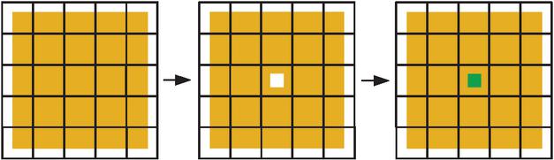
Figure 2 Schematic diagram of a partial modification. The original-structure is the yellow plate, which is divided into multiple blocks by CBFM and represented by black wireframes. Part of the plate is replaced by a green cube structure.
Taking the partial modification in Fig. 2 as an example, it should be pointed out that if the mesh and RWG basis functions within a block remain unchanged, its CBFs are unaffected. Since partial modifications typically affect only a few blocks, such as in Fig. 2, only one block is modified, which means that most CBFs are reusable. In CBFM, generating CBFs is computationally expensive in the solution process. Therefore, the proposed strategy generates CBFs only for the affected blocks when solving a partial modified model, while reusing the CBFs of all other unaffected blocks. Compared to regenerating CBFs for every block, this approach saves considerable computation time without sacrificing accuracy. The process of generating CBFs is the same as that introduced in section II.A.
In addition to reusing the CBFs, we also introduce PMA [12] to reuse the reduced matrix and its solution of the original model. In step 1 of partial modification, all CBFs of the affected blocks are marked as “subtract,” and CBFs on the unaffected blocks are marked as “rest". In step 2, new CBFs need to be regenerated and marked as “added” in these affected blocks, unless the block no longer contains any basis functions. We partitioned the reduced equations of two steps as follows:
| (13) | |
| (20) |
where subscripts , and represent subtracted, rest, and added CBFs, respectively. , and are the reduced self-matrices. , and are the reduced mutual-matrices. , and are the reduced voltage vectors. and are the reduced current vectors in step 1. and are the reduced current vectors in step 2. will be reused, while needs to be recalculated based on the partial modification.
According to the method in [12], the solution of (20) can be efficiently calculated as:
| (21) | ||
| (22) |
where
| (23) | |
| (24) |
and are the submatrices of the inverse of the impedance matrix of the mother-structure [12]. 1 represents the identity matrix.
It can be found that, after solving the original model, can be reused for multiple modifications. Under the condition that PMA is effective, which means the modified structure is much smaller than the original structure, the number of affected CBFs will also be much smaller than the total CBFs, and computational complexity is reduced considerably. To further illustrate the method presented in this paper, pseudocode is provided here.
// Find the computational domain of the original modeland extend it.
Domain = Compute (Original_Mesh);
Domain = Expand (Domain, Distance);
// Divide into blocks and generate CBF
Blocks = Partition (Domain)
for i = 1, BlockNumber
CBFs(i)=Generate_CBF (Blocks(i))
// Generate the reduced matrix and solve
for i = 1, BlockNumber
Vr(i) = FillReducedV (CBFs(i))
for j = 1, BlockNumber
Zr(i, j) = FillReducedZ (CBFs(i), CBFs(j))
Ir = Solve (Zr, Vr)
// Partial modification
New_Mesh=PartialModify (Original_Mesh,
Subtract_Mesh, Add_Mesh)
// Mark affected blocks & CBFs
for i = 1, BlockNumber
MarkCBF (Blocks(i), CBFs(i), New_Mesh)
// PMA
PMA_Sub (CBFs_Ori, CBFs_Sub, Zr, Vr, Ir)
PMA_Add (CBFs_Ori, CBFs_Sub, CBFs_Add, Zr, Vr,Ir)
2.3 MMA for mesh modification
The feasibility of data reuse in partial modification problems stems from the fact that only the mesh of the affected regions needs to be modified, rather than re-discretizing the entire model. Conventional approaches, such as “add-on” technique or PMA, impose significant constraints when modifying partial structures. These methods require the new structure to be predefined during preprocessing, and the mesh of all structures must maintain conformity to ensure current continuity. This requirement is often too complex to satisfy, making these traditional approaches suitable only for cases where the structures are separate. To overcome these limitations, the MMA proposed in [15] allows direct mesh modification without preprocessing software, while preserving current continuity across the structures via the IEDG method [13].
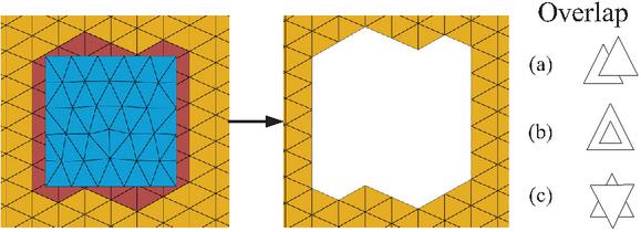
Figure 3 Schematic diagram of removing the triangles from the original-structure that overlap with the subtract shape. Yellow triangles belong to the original-structure, blue triangles belong to the subtract shape, and red triangles overlap with the subtract shape, which belong to the subtract-structure and will be removed. On the right are three situations that will be considered as overlaps.
Some technical details of the MMA in [15] were not elaborated in detail. In this paper, we supplement some important technical details of the MMA. Continuing with the partial modification shown in Fig. 2 as an example, the program will first remove a square from the plane and then replacing it with a cube. To solve this problem, the steps of the MMA are as follows.
Step 1: Identify triangles located inside the subtract-structure, mark and delete them. When a square needs to be subtracted from the original-structure, as illustrated in Fig. 3, the MMA requires a mesh of corresponding shape at the specified position. It then detects all triangles in the original-structure that overlap with the triangles of the mesh of subtract shape and marks them for removal. The overlap between two coplanar triangles only has three cases, as cataloged in Fig. 3 (right). Accordingly, a node-edge detection method is employed here. The method first checks if each node of a triangle is inside another triangle. For triangle ABC and point P, we have
| (25) |
when satisfied
| (26) |
it can be considered that point P is inside the triangle. Then check whether the edges of the two triangles intersect. If two line-segments AB and CD intersect in the same plane, they will satisfy
| (27) |
and triangles that meet either of the checks are marked for removal. The strategy is able to find triangles whose nodes are not inside the subtract shape but overlap with the shape.
For electrically large targets with a very large number of triangles, traversing all triangles of the subtract shape against all triangles of the original structure would be computationally expensive. To accelerate the overlap detection, we can employ a kd-tree [19] spatial index. The original mesh is partitioned using a kd-tree, and only those triangles within intersecting bounding boxes are tested with triangles of the subtract shape.

Figure 4 Diagram of finding the boundary of a subtract shape and moving the nodes of the rest-structure. Blue mesh belongs to the subtract shape, the points in the middle image represent the boundaries of the subtract shape, yellow mesh belongs to the rest-structure, and the triangles in the rest-structure whose nodes have been moved are purple.
Step 2: Move the nodes of rest structure to the square boundary to smooth the jagged edge. As shown in Fig. 4, the MMA first identifies all free edges in the mesh of the subtracted shape, which are defined as edges belonging to only one triangular element and not shared by any adjacent triangles. Subsequently, each node is relocated to the nearest position on the nearest identified edge. Then we uniformly sample points along the edges and move each node to its nearest sample point. This approximation is both fast and effective in improving boundary smoothness.
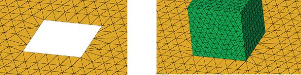
Figure 5 Diagram showing the addition of add-structure to rest-structure. The boundary of the rest-structure, modified by the MMA, precisely matches that of the add-structure, although the meshes are non-conformal.
Step 3: Positioning the add-structure at the modified location and defining RWG and Half-RWG basis functions in the new structure region. As shown in Fig. 5, the green cube is moved to the mesh modification location. Since the different structures are meshed independently, the mesh junctions between them are non-conformal. The current continuity of the non-conformal mesh junctions is guaranteed by the IEDG method [13, 15].
The MMA is based on the principle of removing overlapping triangles and aligning the rest nodes to new boundaries. However, we acknowledge two current limitations. The method is designed for planar subtraction shapes and has not yet been extended to curved surfaces. Additionally, the node relocation step may occasionally generate poorly shaped triangles. Nevertheless, the impact on overall solution accuracy is negligible compared to the significant efficiency gains achieved by avoiding full mesh regeneration.
When integrated with the PMA-CBFM, the MMA enables a powerful solution for partial modification problems. Specifically, the original model is solved using CBFM, and its block partitioning, CBFs and reduced matrix are stored. After the MMA performs a partial mesh modification of arbitrary shape, only the CBFs and reduced sub-matrices related to the affected blocks are regenerated, and the solution of the reduced matrix of the new model is updated via the PMA. This method preserves accuracy while dramatically reducing computational time. Moreover, both the matrix filling and solving processes are inherently parallelizable, further enhancing computational efficiency for electrically large targets. Consequently, the proposed MMA-PMA-CBFM offers a flexible, scalable, and efficient approach for practical engineering applications.
3 NUMERICAL RESULTS
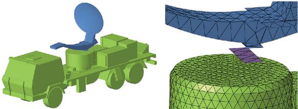
Figure 6 Schematic diagram of radar vehicle models and meshes, with vehicles in green, radar in blue, and the shape of the bottom of the radar in purple.
A numerical example is presented to demonstrate the accuracy and efficiency of our method. As illustrated in Fig. 6, the test case involves a perfect electrical conductor (PEC) radar vehicle model. The main vehicle body is about 5 meters long with 26,934 triangles, which is set as the original-structure. The vehicle has a circular platform where a radar can be placed, which has 1056 triangles. In this example, the MMA-PMA-CBFM performs four partial modifications after solving the vehicle. For each modification process, the program will rotate the radar 90 degrees and place it on the platform to obtain a new model. This example will calculate the monostatic radar cross section (RCS) results over a theta range of 0 to 90 degrees at 500 MHz. The program was performed on a Dell workstation powered by two Intel Xeon E5-2690v2 CPUs and 512 GB of memory.
Table 1 Comparison of memory between MoM and CBFM
| Method | Number of Unknowns | Memory (GB) |
| MoM | 40401 | 12.2 |
| CBFM | 6280 | 0.3 |
Table 1 compares the memory required to store the impedance matrix for the original structure using MoM and CBFM. Since the impedance matrix of the original structure must be stored for reuse during partial modifications, and the modified part is typically small, the memory occupied by the original impedance matrix represents the dominant memory requirement during program execution. As shown in Table 1, CBFM significantly reduces the number of unknowns and memory usage compared to MoM. Consequently, the proposed MMA-PMA-CBFM can solve larger problems than the conventional PMA.
Table 2 Comparison of time between conventional CBFM and MMA-PMA-CBFM
| Method | CBFM | MMA- | MMA-PMA-C |
| PMACBFM | BFM (Parallel) | ||
| Original Structure | 1359.2 s | 1533.8 s | 211.0 s |
| Modify 1 | 1500.4 s | 132.4 s | 19.4 s |
| Modify 2 | 1464.5 s | 164.0 s | 24.1 s |
| Modify 3 | 1451.0 s | 142.6 s | 20.9 s |
| Modify 4 | 1450.7 s | 173.2 s | 25.1 s |
Table 2 compares the single thread solving time of conventional CBFM and proposed MMA-PMA-CBFM. Because MMA-PMA-CBFM extends the computational domain of the radar structure, its block partitioning results differ from those of traditional CBFM, leading to differences in computation time. However, these differences are within an acceptable range. Each partial modification replaces approximately 200 to 400 original CBFs with 700 to 800 new CBFs, and the notable reduction in solving time validates the efficiency of proposed MMA-PMA-CBFM in handling partial modifications problems. In addition, we employ OpenMP to parallelize the filling of the impedance matrix and the voltage vector. The parallel solving time of the proposed method also demonstrates excellent parallel performance.
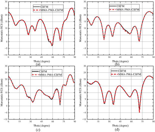
Figure 7 Comparison of monostatic RCS results of four partial modification processes between conventional CBFM and MMA-PMA-CBFM.
Subsequently, we compare the results of MMA-PMA-CBFM with those of the conventional CBFM, as shown in Fig. 7. Furthermore, the root mean square error (RMSE) of the four modifications in is presented in Table 3, with the calculation formula given below:
| (28) | |
| (29) |
It can be seen that the proposed MMA-PMA-CBFM has reliable accuracy performance.
Table 3 RMSE of four modifications
| Modification | RMSE |
| Modify 1 | 2.2 |
| Modify 2 | 1.5 |
| Modify 3 | 1.2 |
| Modify 4 | 1.3 |
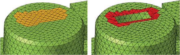
Figure 8 Result of MMA modifying the mesh of the platform to match radar boundaries. Triangles unchanged are green, triangles overlapped and nodes moved are orange (left), and triangle nodes moved are red (right).
Figure 6 illustrates the different mesh required by MMA during partial modification, including mesh of original structure, modified structure, and subtracted shape. MMA first removes triangles that overlap with the radar bottom on the platform, then modifies the shape of the remaining triangles on the platform to match the radar, and finally places the radar. Figure 8 displays the results of a selected modification. It can be seen that the modified mesh matches the boundary of the radar well.
4 CONCLUSION
This paper introduces PMA with MMA into CBFM to enhance computational efficiency for solving electrically large partial modification problems. Compared with the conventional CBFM, the proposed MMA-PMA-CBFM can reduce much CPU time for solving partial modification problems. In future work, MMA-PMA-CBFM can be combined with optimization algorithms to achieve rapid optimization of partial structures.
ACKNOWLEDGMENT
This work was supported in part by the National Nature Science Foundation of China under Grant 62371228 and 62201269, in part by Key Laboratory of Inlet and Exhaust System Technology, Ministry of Education, under Grant CEPE2024012, and in part by the Project of Key Laboratory of Radar Imaging and Microwave Photonics (Nanjing University of Aeronautics and Astronautics), Ministry of Education, under Grant NJ20240005.
REFERENCES
[1] V. Prakash and R. Mittra, “Characteristic basis function method: A new technique for efficient solution of method of moments matrix equation,” Microw. Opt. Technol. Lett., vol. 36, no. 2, pp. 95–100, 2003.
[2] R. Mittra, G. Bianconi, C. Pelletti, K. Du, S. Genovesi, and A. Monorchio, “A computationally efficient technique for prototyping planar antennas and printed circuits for wireless applications,” Proceedings of the IEEE, vol. 100, no. 7, pp. 2122–2131, 2012.
[3] E. Lucente, A. Monorchio, and R. Mittra, “An iteration-free MoM approach based on excitation independent characteristic basis functions for solving large method of moments problems,” IEEE Trans. Antennas Propag., vol. 56, no. 4, pp. 999–1007, 2008.
[4] R. F. Harrington, Field Computation by Moment Methods. New York: MacMillan, 1968.
[5] W. C. Gibson, The Method of Moments in Electromagnetics. Boca Raton: CRC Press, 2007.
[6] K. Zhao, M. N. Vouvakis, and J.-F. Lee, “The adaptive cross approximation algorithm for accelerated method of moments computations of EMC,” IEEE Trans. Electromagn. Compat., vol. 47, no. 4, pp. 763–773, 2005.
[7] J. M. Tamayo, A. Heldring, and J. M. Rius, “Multilevel adaptive cross approximation (MLACA),” IEEE Trans. Antennas Propag., vol. 59, no. 12, pp. 4600–4608, Dec. 2011.
[8] R. Kastner, “An ‘add-on’ method for the analysis of scattering from large planar structures,” IEEE Trans. Antennas Propag., vol. 37, no. 3, pp. 353–361, Mar. 1989.
[9] R. Kastner, “Analysis of microstrip antenna structures using the ‘add-on’ technique,” IEEE Trans. Antennas Propag., vol. 38, no. 1, pp. 114–117, Jan. 1990.
[10] R. Kastner, “On matrix partitioning, the Sherman-Morrison-Woodbury technique and the add-on method,” AP-S Int. Symp. Dig., vol. 1, pp. 15–18, June 1989.
[11] W. Hager, “Updating the inverse of a matrix,” SIAM Rev., vol. 31, no. 2, pp. 221–239, 1989.
[12] X. Chen, C. Gu, Y. Zhang, and R. Mittra, “Analysis of partial geometry modification problems using the partitioned-inverse formula and Sherman-Morrison-Woodbury formula-based method,” IEEE Trans. Antennas Propag., vol. 66, no. 10, pp. 5425–5431, 2018.
[13] Z. Peng, K. H. Lim, and J. F. Lee, “A discontinuous Galerkin surface integral equation method for electromagnetic wave scattering from nonpenetrable targets,” IEEE Trans. Antennas Propag., vol. 61, no. 7, pp. 3617–3628, 2013.
[14] Y. Su, R. Mittra, and W. Sheng, “Analysis of scattering from multi-scale and multiple targets using characteristic basis function (CBFM) and integral equation discontinuous Galerkin (IEDG) methods,” J. Electromagn. Waves Applicat., vol. 31, no. 10, pp. 969–980, 2017.
[15] X. J. Li, Z. A. Shen, X. L. Chen, and C. Q. Gu, “Analysis of partial modification problems using integral equation discontinuous Galerkin with mesh modification algorithm,” IEEE Antennas Wireless Propag. Lett., vol. 20, no. 10, pp. 1948–1952, 2021.
[16] J. Laviada, J. G. Meana, M. R. Pino, and F. Las-Heras, “Analysis of partial modifications on electrically large bodies via characteristic basis functions,” IEEE Antennas Wireless Propag. Lett., vol. 9, pp. 834–837, 2010.
[17] X. L. Chen, C. Q. Gu, Z. Y. Niu, and Z. Li, “Direct solution of electromagnetic scattering using CBFM with ACA algorithm,” in ISAPE2012, Xi’an, China, pp. 1021–1025, 2012.
[18] X. L. Chen, C. Q. Gu, Z. Li, and Z. Y. Niu, “Efficient iterative solution of electromagnetic scattering using adaptive cross approximation enhanced characteristic basis function method,” IET Microwaves, Antennas & Propagation, vol. 9, no. 3, pp. 217–223, 2015.
[19] V. Havran. Heuristic Ray Shooting Algorithms. Department of Computer Science and Engineering, Czech Technical University, Prague, 2000.
BIOGRAPHIES

Ziang Shen received his Bachelor’s degree in 2017 and his Master’s degree in 2020 from Nanjing University of Aeronautics and Astronautics, China, and is presently pursuing the Ph.D. degree. His research focuses on the high-performance computational electromagnetics, specifically the frequency-domain, time-domain, and high-frequency asymptotic algorithms.

Xiaoxing Fang, Ph.D., Associate Professor, graduated from Nanjing University of Aeronautics and Astronautics, China, in 2021. He joined the School of Electronic and Information Engineering at Nanjing University of Information Science and Technology in June 2021. His research focuses on computational electromagnetics, electromagnetic metamaterials and machine learning, and electromagnetic compatibility.

Xinlei Chen received his Ph.D. degree from Nanjing University of Aeronautics and Astronautics in 2015. Currently, he is an Associate Professor at Nanjing University of Aeronautics and Astronautics. He has published over 80 papers in journals and conferences, including IEEE Transactions on Antennas and Propagation and IEEE Antennas Wireless Propagation Letters. His research interests include integral equation methods in electromagnetic problems.

Zhuo Li received his B.Sc. degree in electronic engineering and his M.E. degree in electromagnetic fields and microwave techniques from Nanjing University of Aeronautics and Astronautics (NUAA), Nanjing, China, in 2001 and 2004, respectively, and his Ph.D. degree in radio engineering from the State Key Laboratory of Millimeter Waves, Southeast University, Nanjing, in 2009. From 2015 to 2016, he was a Visiting Scholar with the Department of Physics, Arizona State University, Tempe, AZ, USA. He is currently a Full Professor with the College of Electronic and Information Engineering in NUAA. He has authored or co-authored over 160 papers in refereed journals and conference proceedings, including Advanced Science, Advanced Optical Materials, Nano Letters, Physical Review Applied, IEEE Transactions on Microwave Theory and Techniques, IEEE Transactions on Antennas and Propagation, and IEEE Transactions on Electromagnetic Compatibility. He has filed more than 30 patents. His current research interests include plasmonic metamaterials, MHz-through-THz technologies and transceivers for wireless sensors and biomedical applications, electromagnetic compatibility in avionics system and auto electrical system. He is also interested in the modeling and design of microwave and terahertz photonic circuits and systems.
Li is a Senior Member of Chinese Institute of Electronics and a Committee Member of Antenna Branch of Chinese Institute of Electronics. He received the Second Prize of Natural Science of China Institute of Electronics in 2019 and the NUAA Outstanding Undergraduate Teaching Promotion Award in 2019. He is on the Advisory Board for Journal of Physics D: Applied Physics and on the Review Board for many international journals including Advanced Materials, ACS Photonics, Nanotechnology, Nano-Micro Letters, IEEE T-MTT, IEEE T-AP, and IEEE T-EMC. He also served as the Invited Speaker and Session Chair in many international conferences and workshops.
ACES JOURNAL, Vol. 41, No. 5, 398–405
DOI: 10.13052/2026.ACES.J.410502
© 2026 River Publishers