Development of Mesh-Based Generated Reluctance Network Using Trapezoidal Elements Based on Lumped Parameter Model
Dat Vu Van1, Duc Quang Nguyen4*, Tuan Phung Anh1, Chi Phi Do2, Tung Doan Duc3, Hao Chen5, and Vuong Dang Quoc1*
1School of Electrical and Electronic Engineering Hanoi University of Science and Technology, Vietnam dat.vv221904@sis.hust.edu.vn, tuan.phunganh1@hust.edu.vn, vuong.dangquoc@hust.edu.vn
2Faculty of Electrical-Electronics Cao Thang Technical College, Vietnam dochiphi@caothang.edu.vn
3Faculty of Engineering and Technology Quy Nhon University, Vietnam tung.doanduc@ qnu.edu.vn
4 Department of Electrical Engineering Electric Power University, Viet Nam quangndhtd@epu.edu.vn
5 School of Electrical Engineering China University of Mining and Technology, China hchen@cumt.edu.cn
∗Corresponding Authors
Submitted On: December 07, 2025; Accepted On: March 27, 2026
ABSTRACT
This paper develops a novel Mesh-Based Generated Reluctance NetWork (MBGRN) model, which is based on the lumped parameter modeling method. The mesh-based approach automates network generation, replacing the manual flux path definitions required in traditional magnetic equivalent circuit (MEC). In this approach, the computational domain is represented in a polar coordinate system where the mesh elements are defined as isosceles trapezoids. The model utilizes a rotation simulation to bypass the remeshing processes common in the finite element method (FEM). A key advantage of the proposed MBGRN method is that the number of computational elements is reduced by half compared to the conventional FEM. This leads to a significant reduction in computation time, ranging from 10 to 15 times faster than traditional FEM, while maintaining a calculation error of less than 1% relative to the FEM. The development of this method is validated through a practical benchmark problem: the surface-mounted permanent magnet synchronous motor under no-load condition. The results obtained from the MBGRN model are thoroughly compared with those from the 2D FEM.
Keywords: Finite element method, isosceles trapezoidal elements, lumped parameter model, magnetic equivalent circuit, mesh-based generated reluctance network..
1 INTRODUCTION
The traditional finite element method (FEM) is commonly used to calculate and simulate electromagnetic problems with nonlinearities and complex geometric structures [1]. However, high computational costs and extended processing times limit the applicability of the FEM for tasks requiring rapid simulation, parameter sweeping, or the evaluation of multiple rotor configurations during the design stage [2]. This requirement becomes increasingly critical in modern optimization contexts, which demand a substantial number of iterative calculations.
Lumped parameter models (LPMs) have been developed as an approach to reduce computational costs by representing the electromagnetic domain through reluctance networks and magnetomotive force (MMF) sources [3]. The models based on flux tubes or assumed flux distributions have been utilized in various electrical machine configurations [4, 5, 6, 7, 8, 9, 10]. Nevertheless, these methods rely heavily on geometric assumptions or predefined flux paths; consequently, they may exhibit limitations when applied to complex structures or when accounting for regions of deep saturation.
Another research avenue involves the direct discretization of the computational domain into standard geometric elements [11, 12, 13, 14, 15, 16]. These methods enable a more generalized representation of the electromagnetic field, eliminating the need for a priori assumptions regarding flux paths, while offering the capability to accurately capture leakage and fringing phenomena. However, the majority of existing models employ Cartesian grids [3, 12, 17] and none of these cited studies have addressed the implementation of rotary motion. Given that rotating electrical machines inherently exhibit rotational symmetry, the effective exploitation of polar coordinates remains a significant area of potential.
In this context, the paper proposes a mesh-based generated reluctance network (MBGRN) by using trapezoidal elements based on the LPM. The model employs a single element type with a geometry that naturally accommodates the rotationally symmetric structure of rotating machines, facilitating the direct implementation of periodic boundaries. The rotor motion is modeled by shifting element indices along the angular direction, thereby eliminating the requirement for mesh regeneration or interpolation within the air gap region. Furthermore, the model establishes reluctance branches in two principal directions (radial and tangential), enabling the effective representation of leakage fluxes and local saturation effects. To address material nonlinearity, a damped fixed-point iteration algorithm is utilized to ensure convergence stability.
The validation of the proposed model is tested via the benchmark problem on a surface-mounted permanent magnet synchronous machine (SPMSM), specifically through the no-load condition, in which it is compared against the FEM results in terms of both accuracy and computation time. The model also demonstrates good agreement for fundamental electromagnetic quantities across the investigated scenarios, while achieving a significant reduction in computational cost.
The paper is structured as follows. Section 2 presents the modeling of the mesh element structure. Section 3 develops mathematic model and application test. Section 4 shows the validation test on the practical benchmark problem and discussion. Section 5 presents conclusions and outlines future research directions.
2 PROPOSED MODEL STRUCTURE
2.1 Modeling of element mesh structure
2.1.1 Mesh structure
In rotating electrical machines, the electromagnetic cross-section typically exhibits a circular and centrally symmetric geometry; consequently, the computational domain for the two-dimensional problem is defined in a polar coordinate system (). Depending on the simulation scope, this domain may be configured as an annular sector when examining a fractional segment of the machine—such as one or multiple stator-rotor pole pitches—or as a closed circular region when analyzing the entire electromagnetic space.

Figure 1 Modeling of isosceles trapezoidal element mesh.
The domain is discretized using two coordinate vectors: the radial vector and the angular position vector . Notably, the angular positions are uniformly spaced to facilitate the implementation of rotor rotation (to be detailed in a subsequent section). These coordinates generate a mesh comprising isosceles trapezoidal elements, each bounded by consecutive radii () and adjacent angles (), as illustrated in Fig. 1. The advantages of utilizing an isosceles trapezoidal mesh in polar coordinates include a superior capability to conform to the curved boundaries of the computational domain compared to rectangular grids in Cartesian coordinates. Furthermore, the periodic computational domain can be naturally closed by interconnecting elements in the first and last columns. This topology also facilitates the elimination of non-critical elements located inside the rotor yoke (motor shaft) or outside the stator yoke as shown in Fig. 2.
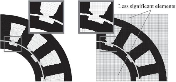
Figure 2 Isosceles trapezoidal mesh in polar coordinates (left) and rectangular mesh in Cartesian coordinates (right).
2.1.2 Elements
Each element comprises a central node connected to four peripheral nodes located at the radial positions (top (t), bottom (b)) and tangential positions (right (r), left (l)). These nodes are linked to the center via a branch consisting of a reluctance in series with a MMF source. By convention, the MMF sources are oriented radially outward for the radial branches () and in the clockwise direction for the tangential branches (). For elements situated at specific boundaries, such as the inner or outer edges, certain nodes or branches may be deactivated in accordance with the imposed boundary conditions as presented in Fig. 3.

Figure 3 Structural configuration and spatial distribution of elements within the 2D mesh grid.
The reluctances of element , bounded by the coordinates as depicted in Fig. 1, are determined by:
| (1) | ||
| (2) | ||
| (3) |
where denotes the element axial length (m), is the permeability of free space, and is the relative permeability.
2.1.3 Assigning materials to elements
The spatial region bounded by an element () may physically encompass multiple distinct materials. However, each element is assigned a single homogeneous material property, determined based on the material occupying the predominant surface area. While this discretization approach may induce geometric distortion or staircase artifacts at complex interfaces, these effects can be effectively mitigated by employing a sufficiently fine mesh as pointed out in Fig. 4.

Figure 4 Computational domain discretized with varying mesh densities.
2.1.4 Modeling of magnetomotive force sources
For the computational domain of rotating electrical machines, the magnetic field is generated by two primary sources of excitation: permanent magnets (PMs) and windings. Consequently, the MMF sources assigned to the network branches are determined by:
| (4) | ||
| (5) |
where , and denote the branch MMFs for each element as depicted in Fig. 3; and represent the angular deviations of the PM magnetization and the winding orientation with respect to the radial axis, respectively; and and correspond to the MMF magnitudes of the magnet and winding, determined by:
| (6) |
where denotes the magnitude of the PM, represents the magnet coercivity, and is the element length along the direction of magnetization. Additionally, indicates the magnitude of the winding MMF, is the vector of phase excitation currents, and is the vector representing the corresponding number of winding turns associated with each element.
2.2 Boundary conditions
In rotating electrical machine modeling, the computational domain is typically restricted to a fractional segment of the motor, corresponding to one or multiple pole pitches. Consequently, the domain exhibits periodicity along the angular direction (). Periodic boundary conditions are applied to the two angular boundaries, as described in [3], ensuring that the magnetic flux distribution at these interfaces is identical, thereby reflecting the inherent symmetry of the electromagnetic structure. In this study, this boundary condition is implemented by interconnecting the elements of the first and last columns via the loop flux variable associated with the final column of the corresponding row, as illustrated in Fig. 5.

Figure 5 Application of periodic and parallel boundary condition.
Along the radial coordinate , the elements situated in the innermost and outermost rows correspond to the inner boundary (e.g., the rotor shaft) and the outer boundary (e.g., the stator housing), respectively. A parallel boundary condition is imposed on these interfaces by eliminating the unconnected reluctances located within the innermost and outermost rows (given already in Fig. 3).
2.3 Implementation of rotary motion
For rotating electrical machines, it is essential to account for the relative motion between the stator and rotor when calculating time- or position-dependent quantities, like flux linkage and back electromotive force (back EMF). In the proposed mesh-based reluctance network, the angular discretization vector exhibits a uniform spacing of . Consequently, the geometric dimensions of all elements situated within the same radial row are identical. This uniformity facilitates the simulation of rotor rotation by an angle through the simultaneous translation of elements representing the rotating components in the direction of motion via an index-shifting operation:
| (7) |
where denotes the elements located in the rows representing the rotating components, is the discrete angular step, and is the total element number along the angular direction (). The modul operation ensures that any index exceeding the limit wraps around to the initial columns, preserving the cyclic continuity of the domain as shown in Fig. 6.

Figure 6 Illustration of the -step element shift operation within the rotating domain.
This approach enables the simulation of rotary motion in a natural manner via element index shifting, thereby completely eliminating the need for re-meshing or complex interpolation algorithms at the sliding interface. Consequently, this method addresses the fundamental limitations associated with the conventional FEM, such as the moving band technique, which typically incur significant computational overhead due to mesh handling and frequently introduce spurious numerical ripples in torque and EMF waveforms arising from variations in element topology [18, 19, 20].
3 MATHEMATIC MODEL AND APPLICATION TEST
3.1 Application test
To visualize the formulation and solution procedure of the generated mesh-based reluctance network, an illustrative example is conducted using the SPMSM. The machine features a 15-slot/10-pole topology equipped with concentrated windings for the threephase stator. The model is constructed within a twodimensional domain representing the machine’s crosssection. The parameters of the proposed motor are given in Table 1.
Table 1 Specifications of the benchmark SPMSM
| Parameter | Value | Unit |
| Rated power | 7500 | W |
| Rated voltage | 200 | V |
| Rated current | 15 | A |
| Rated speed | 1500 | rpm |
| Rated torque | 48 | N.m |
| Number of slots | 15 | – |
| Stator outer diameter | 190 | mm |
| Stator inner diameter | 120 | mm |
| Tooth width | 15 | mm |
| Slot depth | 25 | mm |
| Slot opening depth | 1 | mm |
| Slot opening width | 5 | mm |
| Tooth tip angle | 30 | mm |
| Rated power | 7500 | W |
| Rated voltage | 200 | V |
| Rated current | 15 | A |
| Rated speed | 1500 | rpm |
| Rated torque | 48 | N.m |
| Number of poles | 10 | – |
| Magnet thickness | 3 | mm |
| Magnet coercivity | 852 | kA/m |
| Magnet arc | 140 | degree |
| Air gap length | 1.5 | mm |
| Shaft diameter | 96 | mm |
| Number of phases | 3 | – |
| Winding type | Concentrated | – |
| Turns per phase | 25 | turns |
3.2 Problem formulation and solution procedure
3.2.1 Computational domain definition
For electric motors exhibiting periodic and symmetric structures, the entire rad geometry can be decomposed into k identical periodic sectors, where k denotes the symmetry order. Leveraging this symmetry, the computational burden can be significantly reduced by simulating a single periodic sector rather than the entire machine. Periodic boundary conditions are imposed at the sector boundaries to ensure that the simulation results accurately reflect the magnetic field and current distribution of the full machine. Figure 7 illustrates the computational domain configured for the benchmark motor using the parameters listed in Table 1, where an adaptive mesh is employed.

Figure 7 Reduced periodic computational domain.
3.3 Formulation of the system of equations
Two primary approaches exist for interconnecting mesh elements: the nodal magnetic potential method and the loop flux method [3]. In this study, the loop flux formulation is adopted to establish and solve the governing system of equations. Consider a mesh comprising elements. Given the imposed boundary conditions, a total of loop flux variables are required to fully interconnect the elements within the computational domain. The matrix system is defined as:
| (8) |
where denotes the reluctance matrix, represents the vector of loop flux variables, and corresponds to the MMF source vector.

Figure 8 Components involved in a mesh equation.
Figure 8 illustrates the components constituting the equation associated with the loop flux variable (). These include the central variable and its neighboring variables , along with the corresponding elements , , and .
The governing equation connecting the elements at this specific location is formulated by ensuring that the algebraic sum of magnetic voltage drops around the closed loop equates to zero. Loop flux variables that are rendered invalid due to the imposed boundary conditions are constrained to zero [3]:
| (9) |
Equation (9) exhibits a nonlinear nature, as the elements within the reluctance matrix are directly dependent on the material properties ( and ). Rather than employing the Newton-Raphson method, which is known to be sensitive to discontinuities in the derivative of the magnetization curve, this study selects the Fixed-Point Iteration method due to its inherent simplicity and robustness [21, 22]. To mitigate numerical oscillations frequently observed in regions of deep saturation, an under-relaxation technique is integrated into the solution update process. Consequently, the solution at the ()-th iteration is modulated via a relaxation coefficient :
| (10) |
where denotes the loop flux vector at the current iteration represents the reluctance matrix, corresponds to the source vector, and is the underrelaxation factor (where ). In this study, the relaxation factor is empirically selected within the range of . The detailed solution procedure is schematically illustrated in Fig. 9.

Figure 9 Flowchart of the solution procedure using damped fixed-point iteration.
3.4 Computation of electromagnetic quantities
3.4.1 Magnetic flux distribution
Upon obtaining the solution to Equation (9), the magnetic fluxes flowing through the element branches are determined through the algebraic combination of the associated loop flux variables, governed by the following rule:
| (11) | ||
| (12) | ||
| (13) | ||
| (14) |
The magnetic flux density within each element is determined based on its geometric dimensions and the respective branch flux values:
| (15) | ||
| (16) | ||
| (17) |
The magnetic flux density distribution on the benchmark motor is presented in Fig. 10.
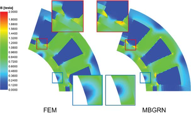
Figure 10 Comparative magnetic flux density distributions between FEM and MBGRN at a specific rotor position.
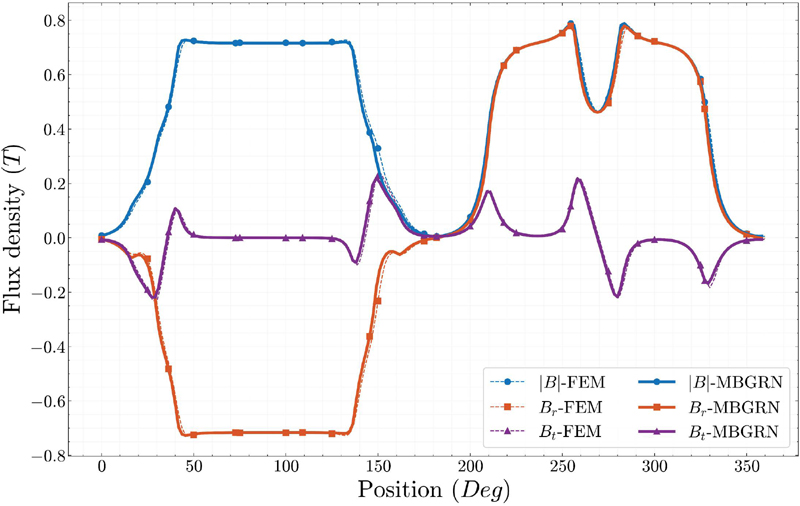
Figure 11 Comparison of air-gap magnetic flux density distribution between FEM and MBGRN.
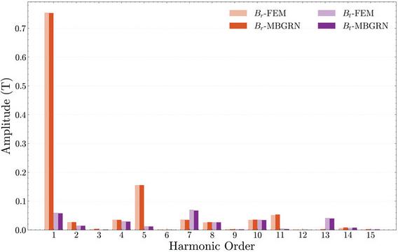
Figure 12 Harmonic spectrum of the air-gap flux density: Comparison between FEM and the proposed MBGRN.
The comparative magnetic flux density distributions between FEM and MBGRN at a specific rotor position are shown in Fig. 10. It can be demonstrated that the magnetic flux distribution calculated by the MBGRN method exhibits a high degree of consistency with that obtained from the FEM. Notably, complex electromagnetic phenomena, including local saturation, leakage flux, and magnetically inactive regions, are accurately captured. This confirms that the MBGRN method achieves a generalized representation of the electromagnetic field without requiring the a priori definition of flux paths, a constraint typical of classical magnetic equivalent circuit (MEC) approaches. Furthermore, the identification of these magnetically inactive regions suggests the potential applicability of the proposed method for multi-physics optimization (e.g., via axial material removal) as investigated in [23, 24].
The following quantitative analyses are performed to objectively evaluate the proposed MBGRN method. The magnetic flux density distribution at the air gap is presented in Fig. 11. Specifically, the statistical results show that the average magnitude of the flux density calculated by MBGRN is 0.4719 T, representing a negligible error of 0.36% compared to the 0.4736 T obtained from FEM. Furthermore, for the radial component (), the MBGRN yields an RMS value of 0.5475 T and a peak value of 0.7794 T, which are in excellent agreement with the FEM results of 0.5481 T (0.1% error) and 0.7731 T, respectively. Moreover, the harmonic analysis of both and components illustrated in Fig. 12 also reveals highly consistent results, further verifying the accuracy of the proposed method in the spectral domain. This high consistency, both numerically and visually, validates that the MBGRN, using isosceles trapezoidal elements, accurately captures the electromagnetic field distribution.
3.4.2 Flux linkage
The flux linkage associated with the -th phase is determined by:
| (18) |
where denotes the flux linkage of phase represents the magnetic circuit symmetry factor, is the total number of elements within the reluctance network, is the number of turns of phase wound on element , and is the flux component flowing through element in the direction orthogonal to the winding cross-section. The calculated phase flux linkages are illustrated in Fig. 13. Specifically, for Phase A, the MBGRN yields a peak flux linkage of 0.2375 Wb and an RMS value of 0.1613 Wb, demonstrating excellent agreement with the FEM results of 0.2399 Wb and 0.1629 Wb, respectively. The maximum relative errors for the peak and RMS values across all phases are approximately 1.04% and 1.13%, respectively. Furthermore, the harmonic analysis presented in Fig. 14 shows a high level of consistency in the spectral domain, confirming that the proposed MBGRN accurately captures the fundamental and harmonic components of the flux linkage compared to the FEM.
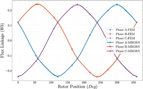
Figure 13 Distribution of flux linkage.
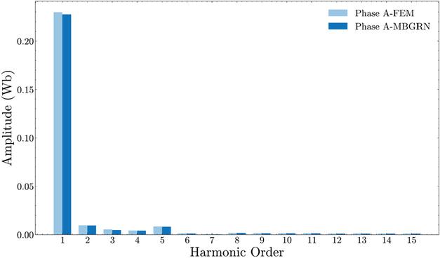
Figure 14 Harmonic spectrum of the flux linkage: comparison between FEM and MBGRN.
3.4.3 Back electromotive force
The back EMF of the -th phase is determined by the time derivative of the corresponding flux linkage:
| (19) |
The phase back-EMF results, obtained by calculating the time-derivative of the phase flux linkages, are illustrated in Fig. 15. The proposed MBGRN method accurately predicts the induced voltage, maintaining a high degree of consistency with the FEM results in terms of both peak and root mean square (RMS) magnitudes. Specifically, for Phase A, the MBGRN yields a peak back-EMF of 193.92 V and an RMS value of 128.09 V, showing excellent agreement with the FEM results of 197.03 V and 129.69 V, respectively. The maximum relative error for the peak voltage across all phases is approximately 1.57%, while the RMS deviation remains within 1.6%. Furthermore, the harmonic analysis presented in Fig. 16 substantiates this accuracy in the spectral domain, confirming that the fundamental and higher-order components, including ripples caused by slot openings, are effectively captured by the MBGRN method.
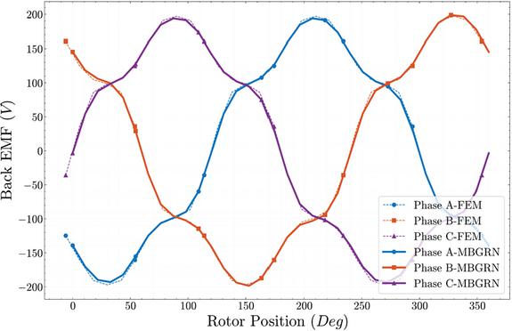
Figure 15 Distribution of back EMF.

Figure 16 Harmonic spectrum of the back EMF: comparison between FEM and MBGRN.
3.4.4 Electromagnetic and cogging torque
For two-dimensional electromagnetic field models, the electromagnetic torque () can be computed by integrating the Maxwell stress tensor as detailed in [25]:
| (20) |
where is the magnetic circuit symmetry factor, is the active axial length of the machine, is closed surface of radius, and represent the radial and tangential magnetic flux densities, respectively.
In the MBGRN model, Equation (20) is discretized, where denotes the elements situated in the -th row (representing the stator-rotor air gap):
| (21) |
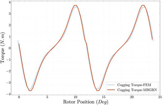
Figure 17 Cogging torque simulation results.
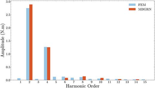
Figure 18 Harmonic spectrum of the cogging torque: comparison between FEM and MBGRN.
The cogging torque characteristics, which are highly sensitive to mesh density and geometric accuracy, are illustrated in Fig. 17. The comparison shows that the proposed MBGRN method effectively predicts the cogging torque profile, with results closely matching the FEM data. Specifically, the MBGRN yields a peak cogging torque of 3.72 Nm and an RMS value of 2.23 Nm, compared to the FEM results of 3.61 Nm and 2.15 Nm, respectively. The maximum relative error for the peak value is approximately 2.98%, while the RMS deviation remains within 3.8%. Furthermore, the harmonic analysis presented in Fig. 18 confirms that the MBGRN accurately captures the dominant harmonic components of the cogging torque, demonstrating the reliability of the proposed model in evaluating parasitic torque components.
4 BENCHMARKING AND VALIDATION
To assess the accuracy and efficiency of the proposed MBGRN, a parametric study is conducted by varying key parameters that exert a significant influence on the computational results. The evaluated parameters include number of mesh elements (which governs both computational speed and solution accuracy), air gap length (a critical determinant of the main flux magnitude), and magnet thickness (which directly correlates with the magnitude of the MMF sources).
To objectively quantify the agreement between the two waveforms, the Normalized Root Mean Square Error (NRMSE) is utilized:
| (22) |
where is the total number of data samples, represents the reference value (FEM) at the -th data point, indicates the computed value (MBGRN) at the -th sample, and and correspond to the maximum and minimum values within the reference dataset, respectively.
The results presented in the subsequent sections were obtained on a workstation featuring a 4-core Intel Core i7-7660U CPU at 2.50 GHz and 8 GB of RAM. The proposed MBGRN algorithm was implemented in Python 3.13 and validated against Ansys Motor-CAD as the industry-standard FEA tool.
4.1 Sensitivity analysis of mesh resolution
In this section, a comparative evaluation is performed on both the FEM and MBGRN by varying the mesh element count for both methods. The primary objectives are to assess the computational speed of the MBGRN and to establish an equitable mesh configuration, thereby ensuring a fair baseline for subsequent comparisons.
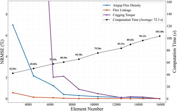
Figure 19 Convergence solution on the mesh of FEM.
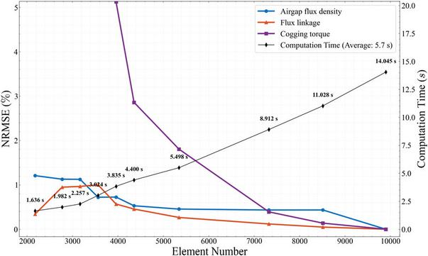
Figure 20 Convergence solution on mesh of MBGRN.
Figures 19 and 20 indicate that the convergence solutions on both the FEM and MBGRN to a stable solution as the number of mesh elements becomes sufficiently large. Notably, the MBGRN method exhibits an average computational speedup of 12.7 times, while requiring an element count approximately half that of the FEM to achieve comparable accuracy. The deviation relative to the method’s asymptotic reference value remains below 2% (representing a mesh density sufficient for convergence).
4.2 Sensitivity analysis of physical parameters
Figures 21 and 22 assess the robustness and accuracy of the MBGRN model under variations in critical physical parameters: air gap length and magnet thickness. The results are presented in terms of the NRMSE, quantifying the discrepancy with the reference FEM results.
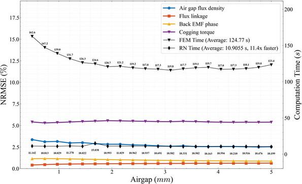
Figure 21 Discrepancy between MBGRN and FEM under air-gap length variations.
Figure 21 shows the error and computation time as the air gap length is varied (0.5 mm to 5 mm). The discrepancies for Flux Linkage and Back EMF remain exceptionally low, consistently below 1% across the entire range of air gap lengths tested. This confirms the MBGRN’s high reliability in predicting the main flux magnitude, regardless of the air gap size. Discrepancies for air-gap flux density are maintained below 3%, while the cogging torque error remains below 6% throughout the entire range of air-gap length variations. The MBGRN consistently maintains an average speed up of 11.4 times over FEM computation time throughout the variation. Figure 22 shows the error and computation time as the magnet thickness is varied (0.5 mm to 4 mm). Similar to the air gap analysis, the NRMSE for flux linkage and back EMF remains very low, consistently below 1%. This confirms the model’s robust performance in predicting these core quantities even when the MMF source magnitude is changed. The NRMSE for air-gap flux density is consistently maintained below 5%, while the cogging torque error gradually increases with magnet thickness, reaching approximately 6% at a thickness of 4 mm. The significant advantage in computation speed is maintained, with the MBGRN being an average of 10.9 times faster than the FEM.

Figure 22 Discrepancy between MBGRN and FEM under magnet thickness variations.
5 CONCLUSION
This paper has successfully developed and implemented the MBGRN model within a polar coordinate system. This encompasses the entire modeling process, including mesh generation using isosceles trapezoidal elements, material assignment, system formulation, nonlinear handling, and the simulation of rotary motion via a unique index-shifting technique. This approach eliminates the requirement for mesh regeneration or complex interpolation algorithms at the sliding interface, providing a more natural representation of motion compared to conventional FEM techniques. As an LPM, the MBGRN is a discrete approximation that effectively accounts for local magnetic saturation. While it is not intended to replace high-fidelity FEM continuum analysis, it serves as an efficient alternative for rapid design. Optimized for rotational symmetry, the current framework is limited to symmetric domains and does not account for asymmetric configurations such as rotor eccentricity. For these symmetric cases, MBGRN offers significant speed advantages in parameter sweeping while maintaining the ability to capture nonlinear magnetic behavior. Validation results obtained from the SPMSM under the no-load condition demonstrate that the model achieves high accuracy. Specifically, it yields discrepancies of less than 1% for primary quantities such as flux linkage and back EMF. Discrepancies are also below 5% for air-gap magnetic flux density and cogging torque. Furthermore, the model achieves a computational speedup of 10 to 15 times compared to the FEM. This speedup is realized while requiring approximately half the number of elements. These findings confirm the potential of the MBGRN for applications requiring rapid simulation, parametric analysis, and design optimization of rotating electrical machines. The significant reduction in computation time confirmed in this study is especially critical for expanding this framework to 3D models, where the computational cost of traditional FEM often becomes prohibitive.
Building upon the proposed MBGRN framework and the robust iterative solver, future research directions will focus on several key areas:
• Expanding application to machines with stronger nonlinearity (IPMSM, SynRM).
• Investigation of full-load conditions and the incorporation of magnetic losses within the magnetic circuit.
• Prioritizing a 3D model to capture axial end effects and end-winding leakage flux, maximizing speed advantage over 3D FEM.
• Integrating with topology optimization for multi-physics challenges, particularly optimizing rotor voids for inertia reduction and enhanced cooling.
The full source code of the proposed method is given at: https://github.com/iamvuvandat/Mesh\_Based\_Reluctance\_Generated\_Network\_2D. The provided GitHub repository includes the following key components and scripts:
• Core solver with nonlinear magnetic iteration.
• Mesh generation tools in polar coordinates using isosceles trapezoidal elements.
• Scripts for computing flux density, flux linkage, back EMF and cogging torque.
• Benchmark configurations used in this paper to ensure reproducibility.
ACKNOWLEDGMENT
This research is funded by Hanoi University of Science and Technology (HUST) under project number T2025-PC-082.
REFERENCES
[1] M. N. Sadiku, “A simple introduction to finite element analysis of electromagnetic problems,” IEEE Transactions on Education, vol. 32, no. 2, pp. 85–93, 2002.
[2] G. Lei, J. Zhu, Y. Guo, C. Liu, and B. Ma, “A review of design optimization methods for electrical machines,” Energies, vol. 10, no. 12, p. 1962, 2017.
[3] S. Yang, S. Asfirane, S. Hlioui, S. Mezani, G. Krebs, and Y. Amara, “Introduction to mesh based generated lumped parameter models for electromagnetic problems,” CES Transactions on Electrical Machines and Systems, vol. 5, no. 2, pp. 152–162, 2021.
[4] E. Fleurot, F. Scuiller, and J.-F. Charpentier, “Analytical models for fast and accurate calculation of electromagnetic performances of segmented permanent magnet synchronous machines with large angular gaps,” Applied Sciences, vol. 11, no. 1, p. 459, 2021.
[5] R. M. Bhashini and K. Ragavan, “Magnetic equivalent circuit for surface-mounted pm motor,” in 2018 IEEE International Conference on Power Electronics, Drives and Energy Systems (PEDES), pp. 1–5, 2018.
[6] S.-M. Kim, W.-S. Jung, W.-H. Kim, T.-K. Bang, D.-H. Lee, Y.-J. Kim, and J.-Y. Choi, “Optimal design of permanent magnet synchronous machine based on random walk method and semi 3D magnetic equivalent circuit considering overhang effect,” Energies, vol. 15, no. 21, p. 7852, 2022.
[7] C. Rasmussen and E. Ritchie, “A magnetic equivalent circuit approach for predicting PM motor performance,” in IAS’97. Conference Record of the 1997 IEEE Industry Applications Conference Thirty Second IAS Annual Meeting, vol. 1, pp. 10–17, 1997.
[8] L. Dang, N. Bernard, N. Bracikowski, and G. Berthiau, “Analytical model and reluctance network for high-speed PMSM design optimization application to electric vehicles,” in 2016 XXII International Conference on Electrical Machines (ICEM), pp. 1359–1365, 2016.
[9] R. Jayarajan, N. Fernando, A. Mahmoudi, and N. Ullah, “Magnetic equivalent circuit modelling of synchronous reluctance motors,” Energies, vol. 15, no. 12, p. 4422, 2022.
[10] V. Naeini and N. Sadeghi, “Optimum design of the outer rotor brushless DC permanent magnet motor with minimum torque ripples,” Journal of Operation and Automation in Power Engineering, vol. 14, no. 1, pp. 70–76, 2026.
[11] S. Yang, Y. Amara, W. Hua, and G. Barakat, “Development of a generic framework for lumped parameter modeling,” Open Physics, vol. 18, no. 1, pp. 365–373, 2020.
[12] S. Ouagued, Y. Amara, and G. Barakat, “Comparison of hybrid analytical modelling and reluctance network modelling for pre-design purposes,” Mathematics and Computers in Simulation, vol. 130, pp. 3–21, 2016.
[13] K. Pluk, J. Jansen, and E. Lomonova, “3-D hybrid analytical modeling: 3-D Fourier modeling combined with mesh-based 3-D magnetic equivalent circuits,” IEEE Transactions on Magnetics, vol. 51, no. 12, pp. 1–14, 2015.
[14] Z. Liu, C. Tang, Y. He, and J. Chen, “A 2D generalized equivalent magnetic network model for electromagnetic performance analysis of surface-mounted permanent magnet electric machines,” Electronics, vol. 14, no. 8, p. 1642, 2025.
[15] W. Lu, J. Zhu, Y. Fang, and P.-D. Pfister, “A hybrid analytical model for the electromagnetic analysis of surface-mounted permanent-magnet machines considering stator saturation,” Energies, vol. 16, no. 3, p. 1300, 2023.
[16] S. Asfirane, S. Hlioui, Y. Amara, and M. Gabsi, “Study of a hybrid excitation synchronous machine: Modeling and experimental validation,” Mathematical and Computational Applications, vol. 24, no. 2, p. 34, 2019.
[17] D. Ceylan, L. A. Friedrich, K. O. Boynov, and E. A. Lomonova, “Convergence analysis of the fixed-point method with the hybrid analytical modeling for 2-D nonlinear magnetostatic problems,” IEEE Transactions on Magnetics, vol. 57, no. 2, pp. 1–5, 2020.
[18] X. Shi, Y. Le Menach, J.-P. Ducreux, and F. Piriou, “Comparison of slip surface and moving band techniques for modelling movement in 3D with FEM,” COMPEL-The International Journal for Computation and Mathematics in Electrical and Electronic Engineering, vol. 25, no. 1, pp. 17–30, 2006.
[19] S. L. Ho, W. Fu, and H. Wong, “Direct modeling of the starting process of skewed rotor induction motors using a multi-slice technique,” IEEE Transactions on Energy Conversion, vol. 14, no. 4, pp. 1253–1258, 2002.
[20] A. Demenko, “Movement simulation in finite element analysis of electric machine dynamics,” IEEE Transactions on Magnetics, vol. 32, no. 3, pp. 1553–1556, 1996.
[21] E. Dlala, A. Belahcen, and A. Arkkio, “A fast fixed-point method for solving magnetic field problems in media of hysteresis,” IEEE Transactions on Magnetics, vol. 44, no. 6, pp. 1214–1217, 2008.
[22] A. Zhou, D. Lin, C. Lu, M. Rosu, and D. Ionel, “An adaptive fixed-point iteration algorithm for finite element analysis with magnetic hysteresis materials,” IEEE Transactions on Magnetics, vol. 53, no. 10, pp. 1–5, 2017.
[23] T. Cherrière, S. Hlioui, L. Laurent, F. Louf, H. B. Ahmed, and M. Gabsi, “Topology optimization of asymmetric PMSM rotor,” in 2022 International Conference on Electrical Machines (ICEM), pp. 469–475, 2022.
[24] S. Sato, T. Sato, and H. Igarashi, “Topology optimization of synchronous reluctance motor using normalized gaussian network,” IEEE Transactions on Magnetics, vol. 51, no. 3, pp. 1–4, 2015.
[25] D. M. Ionel, M. Popescu, M. I. McGilp, T. Miller, and S. J. Dellinger, “Assessment of torque components in brushless permanent-magnet machines through numerical analysis of the electromagnetic field,” IEEE Transactions on Industry Applications, vol. 41, no. 5, pp. 1149–1158, 2005.
BIOGRAPHIES

Dat Vu Van is currently a student at the School of Electrical and Electronic Engineering, Hanoi University of Science and Technology, Vietnam. His research interests include the modeling of electrical machines, analytical and finite element methods.

Duc Quang Nguyen received his Engineer diploma degree from the Hanoi University of Science and Technology, Vietnam, in 2007; M.S. from Lille 1 University, France, in 2009, and Ph.D. from the Ecole Nationale Superieure d’Arts et Metiers Paristech, France, in 2013. All were in electrical engineering. He is currently a Lecturer in the Department of Electrical Engineering, at the Electric Power University, Vietnam. His research interests are in the fields of numerical modeling methods, electromagnetic field, electrical machines, and BESS.

Tuan Phung Anh obtained his Ph.D. degree in Electrical Engineering in 2006 from Grenoble Institute of Technology (Grenoble INP), France. He is currently a Senior Lecturer at the Faculty of Electrical Engineering, School of Electrical and Electronic Engineering, Hanoi University of Science and Technology (HUST), Vietnam. His research interests include electromagnetic design, optimization algorithms, magnetic field stealth, and the application of advanced materials in electrical engineering.

Chi Phi Do is a Dean in Electrical-Electronic Engineering, Cao Thang Technical College, Ho Chi Minh City, Vietnam. He received his Ph.D. from Hanoi University of Science and Technology in 2016. His research interests include electrical engineering, electrical installation skills, design and install of solar or lighting systems, ability to operate, assemble, maintain electrical equipment, electrical systems, and solve problems related to electricity and equipment in the production.

Tung Doan Duc received the B.Eng. degree in Electrical Engineering in 2000, the M.Eng. degree in Electrical Engineering in 2004, and the Ph.D. degree in Electrical Engineering in 2009, all from Hanoi University of Science and Technology, Vietnam. He is currently Rector of Quy Nhon University. He became an Associate Professor in 2019. His research interests include electrical machines, optimization techniques in electrical machines and power systems, and smart grids.

Hao Chen (Senior Member, IEEE) received the B.S. and Ph.D. degrees in electrical engineering from the Department of Automatic Control, Nanjing University of Aeronautics and Astronautics, Nanjing, China, in 1991 and 1996, respectively. In 1998, he became an Associate Professor at the School of Information and Electrical Engineering, China University of Mining and Technology, Xuzhou, where he has been a Professor since 2001. From 2002 to 2003, he was a Visiting Professor at Kyungsung University, Busan, South Korea. Since 2008, he is Adjunct Professor at The University of Western Australia, Perth, WA, Australia. He is the author of one book and has authored more than 300 papers. He holds 15 US patents, 87 Chinese invention patents, and six Chinese utility model patents.

Vuong Dang Quoc received his Ph.D. degree in 2013 from the Faculty of Applied Sciences at the University of Liège in Belgium. He joined Hanoi University of Science and Technology in September 2013, where he is currently working as a deputy director, Training Center of Electrical Engineering, School of Electrical Engineering, University of Science and Technology, Hanoi, Vietnam. He became an associate professor in 2020. Dang Quoc Vuong’s research domain encompasses modeling of electromagnetic systems, electrical machines, optimization method, numerical methods, and subproblem methods.
ACES JOURNAL, Vol. 41, No. 4, 376–388
DOI: 10.13052/2026.ACES.J.410410
© 2025 River Publishers