A Bear-Shaped UWB MIMO Antenna Based on Characteristic Mode Analysis
Xiaoyan Wei1, Zhonggen Wang1*, Wenyan Nie2, Chenlu Li3, and Zhengting Zhang1
1School of Electrical and Information Engineering Anhui University of Science and Technology, Huainan 232001, China
xywei1216@163.com, zgwang@ahu.edu.cn, ztzhang818@163.com
2School of Mechanical and Electrical Engineering Huainan Normal University, Huainan 232001, China
wynie5240@163.com
3School of Electrical and Information Engineering Hefei Normal University, Hefei 230061, China
chenluli@hfnu.edu.cn
*Corresponding author
Submitted On: December 23, 2025 Accepted On: July 23, 2026
ABSTRACT
This paper proposes a compact four-port ultra-wideband (UWB) multiple-input multiple-output (MIMO) antenna with bear-shaped patches based on characteristic mode analysis (CMA). The antenna measures , comprising orthogonally arranged bear-shaped radiating elements on the top layer, a cross-shaped hollowed-out decoupling structure on the bottom layer, and defected ground structures (DGS) with corner cuts and grooves at the four corners. Notably, the bear-shaped radiating elements are not just a morphological innovation; compared with traditional rectangular/circular elements, their irregular outline enriches equivalent current path diversity and increases excited resonant modes. Each antenna is optimized with etched slots, corner cuts and a T-shaped feeder, ensuring simultaneous excitation of five characteristic modes for UWB performance. For the MIMO configuration, mutual coupling is suppressed via orthogonal arrangement, the decoupling structure and DGS, with isolation over 20 dB. Simulations and measurements confirm the antenna operates in the 3.36–21.91 GHz band, featuring S11 10 dB and ECC 0.005 across the band, a diversity gain approaching 9.9999 dB, 75–95% radiation efficiency, 7 dBi peak gain and a group delay less than 1 ns. This design outperforms existing designs in bandwidth, isolation and miniaturization, suited for advanced wireless communication scenarios requiring wide bandwidth, high isolation and a compact form factor.
Keywords: Characteristic mode theory, defected ground structures, MIMO antenna, T-shaped feeder, ultra-wideband antenna..
1 INTRODUCTION
With advances in wireless communication technologies, demand for bandwidth capacity and data transmission rates has grown exponentially [1]. Ultra-wideband (UWB) technology offers unique advantages including ultra-wide bandwidth, high temporal resolution enabled by nanosecond pulses and low power consumption. It is well suited for short-range high-speed data transmission [2, 3] and precise positioning, and holds broad application potential in radar, Internet of Things (IoT) and vehicle-to-everything (V2X) [4]. Despite these merits, UWB faces multipath fading. Multiple-input multiple-output (MIMO) technology addresses this challenge via multi-antenna spatial diversity and multiplexing [5, 6], which enhances system capacity and reliability. Integrating UWB and MIMO has yielded devices that boost wireless communication capacity and transmission rates while mitigating multipath effects.
For MIMO systems, isolation stands as a paramount indicator of diversity performance and, to tackle the coupling issue between antenna elements, researchers have elaborated various decoupling techniques such as decoupling stubs [7], defected ground structures (DGS) [8, 9], and electromagnetic bandgaps (EBG) [10]. Among these, a neutralization line composed of a disk and metal strips is applied to antenna elements to effectively enhance isolation [11], while a square decoupling structure is placed between antenna elements to mitigate mutual coupling [12]. For bandwidth enhancement, slotting microstrip lines improves impedance matching and broadens the operating band [13]. An improved embedded feed combined with a slotted ground plane is used to extend the bandwidth without compromising radiation performance [14]. By utilizing two distinct UWB antenna elements to excite different resonant modes, a bandwidth of 2.6–11 GHz is achieved while maintaining high isolation [15]. UWB performance is attained by slotting the antenna radiating patch and engineering a defected ground plane [16]. Extending circular elements with a backplane and truncating rectangular elements expands the operating bandwidth while preserving stable radiation characteristics [17]. Finally, a planar low-profile microstrip patch antenna sandwiched between a finite ground plane and a surface is presented, achieving an impedance bandwidth of 2–11.2 GHz [18].
Although various technologies have been applied to the design of UWB MIMO antennas, many existing designs still rely on the trial-and-error method, often lacking sufficient theoretical guidance and physical insight. Characteristic mode analysis (CMA), on the other hand, enables targeted structural optimization by revealing modal characteristics. It has been shown to facilitate performance improvements in a range of antenna designs [19, 20, 21, 22], as exemplified below. For instance, a low-profile wideband circularly polarized antenna is presented in [19], where four linearly polarized modes are adjusted to the target frequency band via CMA. A probe-fed grounded antenna with a sandwich structure is proposed in [20]; CMA reveals that this configuration excites the and modes, resulting in a monopole-like radiation pattern with low cross-polarization. A tri-band circularly polarized metasurface antenna is developed in [21] using CMA, where the metasurface unit structure is modified to suppress reverse currents and excite desired resonant modes. Furthermore, a compact wideband dual-polarized antenna with high isolation is reported in [22]; CMA is utilized to narrow the patch center and introduce a U-shaped slot into the L-shaped probe, effectively suppressing higher-order modes.
In summary, this paper proposes a compact UWB MIMO antenna consisting of four bear-shaped radiating elements and four DGS. Bandwidth and isolation are improved by introducing a cross-shaped decoupling structure, adding L-shaped branches to the stubs, and etching rectangular slots and triangular slots on the DGS. The antenna operates in the frequency band of 3.36–21.91 GHz, covering the UWB range. It achieves an isolation of more than 20 dB across the entire band and a peak gain of 7 dBi, with excellent radiation performance and diversity performance. In addition, the design evolution of the antenna is guided by CMA. By analyzing the modal current and electric field distributions, the feeding points of the rectangular microstrip lines for the radiating elements are determined. This ensures the simultaneous excitation of five characteristic modes, effectively achieving UWB operation.
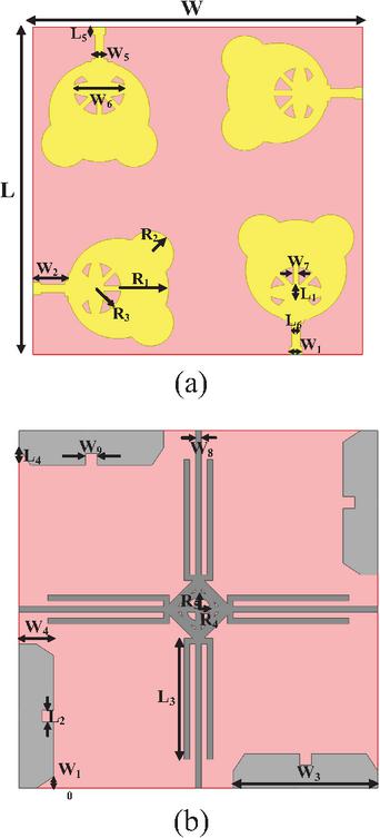
Figure 1 UWB MIMO antenna structure: (a) top-side antenna structure, (b) bottom-side antenna structure.
2 ANTENNA DESIGN
2.1 Antenna structure
Figure 1 illustrates the overall geometric structure of the four-port MIMO antenna. The antenna has an overall size of and is printed on an FR4 dielectric substrate with a relative permittivity () of 4.4 and a loss tangent of 0.02, employing a 50 microstrip line for feeding. Table 1 presents the detailed optimized parameter values. The antenna’s radiating elements are bear-shaped patches, which are arranged orthogonally on the top layer of the dielectric substrate in a compact configuration to maximize utilization of the substrate space. On the bottom layer of the dielectric substrate, the four corners of the ground plane incorporate cut-angle and groove structures, which optimize grounding performance and further enhance isolation between elements. Moreover, a cross-intersecting microstrip line structure is positioned in the central area. This cross-intersecting structure consists of multiple microstrip lines intersecting in a cross pattern with hollow geometric patterns in the middle, and it mitigates electromagnetic coupling between antenna elements by regulating the current distribution. Collectively, the bottom-layer structures work in conjunction with the top-layer radiating elements, enabling the MIMO antenna to achieve wideband operation and high isolation characteristics.
Table 1 Parameter dimensions of the antenna
| Parameter | L | L1 | L2 | L3 | L4 | L5 |
| Value (mm) | 62 | 3.12 | 2 | 21 | 3 | 1.51 |
| Parameter | L6 | W | W1 | W2 | W3 | W4 |
| Value (mm) | 1.6 | 62 | 2.3 | 6.02 | 25 | 6 |
| Parameter | W5 | W6 | W7 | W8 | W9 | W10 |
| Value (mm) | 3 | 10.92 | 1 | 1 | 2 | 2 |
| Parameter | R1 | R2 | R3 | R4 | R5 | |
| Value (mm) | 9.5 | 4.4 | 4.8 | 2 | 3 |
2.2 Design and analysis of a single antenna based on characteristic mode
To systematically optimize the UWB performance of the proposed bear-shaped structure, CMA is employed as the core theoretical guidance throughout the antenna design process. Based on the Method of Moments (MoM), CMA solves the generalized eigenvalue equation , extracting the inherent characteristic modes of the structure. These modes are independent of any specific excitation source. Each mode is characterized by a Modal Significance (MS) value indicating its excitability and a Characteristic Angle (CA) reflecting its resonant state, with the corresponding modal current distribution revealing the spatial locations of strong currents on the conductor surface. In the proposed design, CMA first identifies the candidate characteristic modes and evaluates their excitation feasibility by examining whether their current distributions are concentrated near the feeding port, which reveals that only three of the five candidate modes are initially excitable. CMA then guides the subsequent structural modifications, including the radial slot, ground plane truncations, rectangular slot, and T-shaped feeder, to adjust the modal current distributions of the remaining modes to overlap with the feeding region and shift their resonant frequencies into the target band to collectively cover a continuous ultra-wide bandwidth. Through this iterative CMA-guided optimization, all five characteristic modes are eventually excited simultaneously, achieving continuous UWB operation. The effectiveness of this approach is validated through the structural evolution from Antenna 1 to Antenna 3, supported by MS, CA, and modal current distribution analyses presented below.
Figure 2 illustrates the structural evolution process of the single antenna, and Fig. 3 presents the corresponding simulated S-parameters. The single antenna is fabricated on an FR4 substrate with dimensions of . The evolved structure is modeled and subjected to CMA using the commercial CST (Computer Simulation Technology) software. Figure 4 shows the MS and CA of Antenna 1, and Fig. 5 presents the modal current distributions at resonance. MS indicates the contribution degree of each mode within a specific frequency range. A value close to 1 means the mode is more likely to be excited under appropriate excitation, while a value below 0.707 indicates a low probability of resonance. CA reflects the resonant characteristics of the mode. A value close to 180∘ indicates a stronger resonant condition.
As shown in Fig. 4, among the 12 characteristic modes, modes 1, 2, 4, 5, and 11 can theoretically be excited under appropriate excitation. However, as illustrated in Fig. 5, the currents of modes 4 and 11 are primarily distributed on the edge of the bear-shaped patch and the middle section of the feeder as well as the upper edge of the ground plane, respectively. Since these strong-current regions are distant from the feeding port and mode 4 further exhibits low current intensity, their contribution to the antenna’s bandwidth is limited; in contrast, modes 1, 2, and 5 exhibit intense current concentration in the feeder and adjacent ground regions, facilitating their effective excitation. Nevertheless, the combined bandwidth supported by these three modes remains inadequate to satisfy UWB requirements. The S-parameter curve of Antenna 1 (Fig. 3) reveals that its dual operating bands span 3.47–8.75 GHz and 10.39–16.79 GHz, neither of which complies with UWB standards. Accordingly, optimization of the antenna structure is necessitated, with the optimized structure presented in Fig. 2 (b).
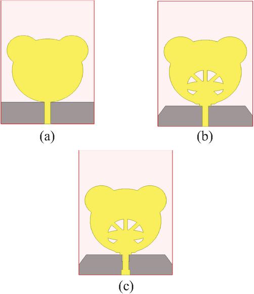
Figure 2 Evolutionary process of antenna structure: (a) Antenna 1, (b) Antenna 2, and (c) Antenna 3.
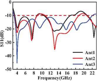
Figure 3 Simulated S-parameter plot of the antenna.
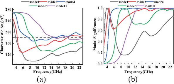
Figure 4 Simulated results of mode analysis of Antenna 1: (a) Modal Significance and (b) Characteristic Angle.
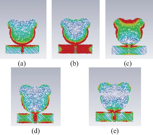
Figure 5 Simulated mode current distribution of Antenna 1: (a) mode 1 at 3.89 GHz, (b) mode 2 at 4.35 GHz, (c) mode 4 at 7.49 GHz, (d) mode 5 at 8.95 GHz, (e) mode 11 at 15.01 GHz.
As shown in Fig. 2 (b), compared with Antenna 1, Antenna 2 has a radial slot etched into the circular section of its patch, and isosceles right triangles are truncated from both the left and right sides of the ground plane. The radial slot disrupts the continuous current flow on the circular head region, effectively lengthening the current path for modes whose currents are concentrated on this region, which shifts their resonant frequencies downward. Meanwhile, the truncated isosceles right triangles remove ground plane area near the edges, modifying the ground current return paths and enhancing current density on the remaining ground surface, which promotes the excitation of higher-order modes and extends the highfrequency band by approximately 2 GHz.
Figure 6 presents the MS and CA of Antenna 2, and Fig. 7 illustrates the corresponding modal current distributions. In contrast to Antenna 1, Antenna 2 exhibits altered characteristic mode configurations and extended effective bandwidth. The resonant frequency of mode 4 decreases slightly due to the lengthened current path introduced by the radial slot. However, its current is predominantly concentrated above the bear-shaped patch and distant from the feeding port, so it cannot be excited. The resonant frequencies of modes 1, 2, and 5 exhibit a slight upward shift, as the triangular ground truncations redirect their current distributions toward the ground plane edges, shortening the effective current return path for these modes. As depicted in Fig. 7, they can be effectively excited owing to their strong localized distribution in the vicinity of the feeding port. The resonant frequency of mode 11 is reduced by approximately 0.2 GHz, as the radial slot also disrupts the high-frequency current paths on the upper part of the patch. The S-parameter curve in Fig. 3 indicates that the high-frequency band of Antenna 2 is extended by 2 GHz, reducing the bandwidth gap to 9.5–10.2 GHz. However, impedance matching in the 9–11 GHz range is still not fully satisfactory, so further optimization of Antenna 2’s structure is required.
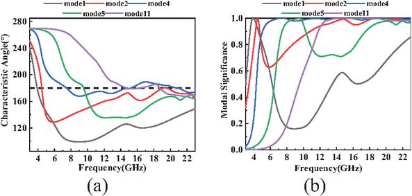
Figure 6 Simulated results of mode analysis of Antenna 2: (a) Modal Significance and (b) Characteristic Angle.
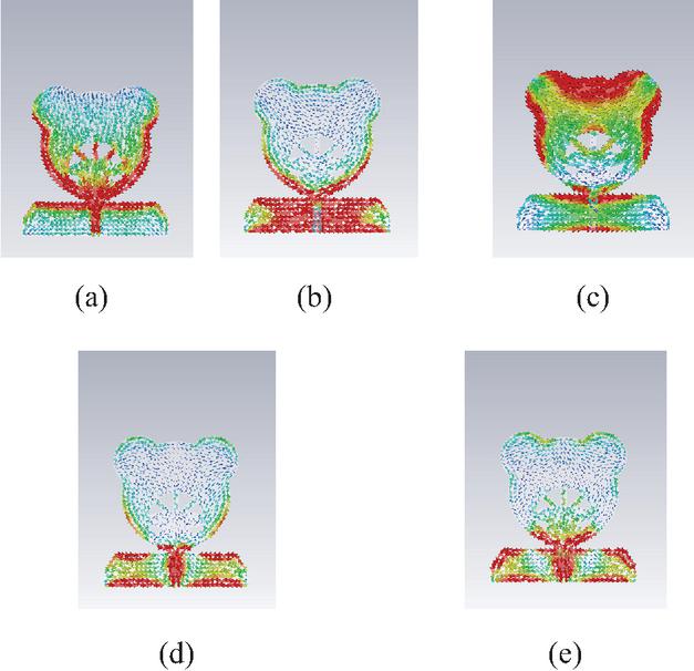
Figure 7 Simulated mode current distribution of Antenna 2: (a) mode 1 at 3.91 GHz, (b) mode 2 at 4.47 GHz, (c) mode 4 at 7.45 GHz, (d) mode 5 at 9.51 GHz, (e) mode 11 at 14.81 GHz.
To shift the characteristic modes toward lower frequencies and ensure their excitation, as shown in Fig. 2 (c), Antenna 3 has a rectangular slot etched into the ground plane and adopts a T-shaped feeder. The rectangular slot introduces an additional current discontinuity in the ground plane, which redirects the surface current of mode 4 (previously concentrated far from the feeding port) toward the feeding region. The T-shaped feeder provides broader capacitive coupling to the radiating patch compared with the original microstrip line, improving impedance matching across multiple resonant frequencies simultaneously. These modifications collectively redirect current concentrations toward the feeding port, enabling the simultaneous excitation of five modes and extending the effective bandwidth to cover the majority of the UWB range.
Figure 8 presents the MS and CA of Antenna 3. Figure 9 illustrates the modal current distributions at resonance. A comparison of Figs. 9 and 7 reveals key changes. As predicted by the mechanism discussed above, mode 4 becomes excitable in Antenna 3, which broadens the bandwidth. The resonant frequencies of modes 1, 2, 4, and 5 shift downward, attributable to the increased effective current path lengths caused by the ground plane slot and the modified coupling characteristics of the T-shaped feeder. The resonant frequency of mode 11 shifts upward by 4 GHz, which is consistent with the altered current distribution at higher frequencies due to the combined effect of the ground plane modification and the feeder redesign. As shown in Fig. 9, the current for each mode is strengthened and concentrated near the feeding port, confirming that the structural modifications successfully reshape the modal current distributions to facilitate their effective excitation. Figure 8 further indicates the combined bandwidth of these modes, fully covering the 3.28–22.01 GHz range. S-parameter results in Fig. 3 confirm that the simulated operating frequency band of Antenna 3 is 3.28–22.01 GHz, which is consistent with the measured result of 3.36–21.91 GHz presented in section 3. To further verify the radiation performance of the optimized single antenna across the entire UWB, its radiation patterns at three representative frequencies are analyzed below.
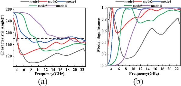
Figure 8 Simulated results of mode analysis of Antenna 3: (a) Modal Significance and (b) Characteristic Angle.
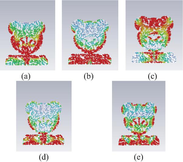
Figure 9 Simulated mode current distribution of Antenna 3: (a) mode 1 at 3.85 GHz, (b) mode 2 at 4.27 GHz, (c) mode 4 at 7.23 GHz, (d) mode 5 at 9.35 GHz, (e) mode 11 at 18.81 GHz.
The CMA results presented above can be further interpreted in terms of the physical role of each geometric feature. Conventional rectangular or circular patches exhibit relatively uniform current path lengths, which limits the number of distinct resonant modes that can be effectively excited. The bear-shaped geometry overcomes this limitation through its irregular bionic outline. Specifically, the circular head region provides current paths analogous to those on circular patches, supporting lower-order modes (modes 1 and 2) in the 3–5 GHz range, as confirmed by the modal current distributions in Figs. 5, 7, and 9. The protruding ear structures introduce current path segments with shorter effective lengths, contributing to higher-order mode excitation at mid-band frequencies. Meanwhile, the tapered body section and the concave transitions between the ears and the face create geometric discontinuities that redistribute surface current density, increasing the frequency separation between adjacent modes and reducing modal overlap. While the bear-shaped patch inherently supports five significant characteristic modes within the 3.28–22.01 GHz band, only three of these modes (modes 1, 2, and 5) are initially excitable, as the currents of modes 4 and 11 are concentrated far from the feeding port. These geometric features collectively provide the rich modal diversity that, combined with the structural optimizations described above, enables the simultaneous excitation of all five characteristic modes for continuous UWB operation.
Figure 10 presents the simulated co-polarization (solid lines) and cross-polarization (dashed lines) normalized radiation patterns of the optimized single antenna (Antenna 3) at three representative frequencies, 4.6 GHz, 15.4 GHz, and 18.5 GHz, covering the low-, mid-, and high-frequency regions of the UWB operating band. At 4.6 GHz, the antenna exhibits a typical dipole-like radiation characteristic, with the E-plane () showing a standard figure-of-eight pattern and the H-plane () presenting quasi-omnidirectional radiation behavior. The cross-polarization level is approximately 15–20 dB below the co-polarized component in the main radiation direction, indicating good polarization purity. At 15.4 GHz, the increased electrical size of the antenna leads to slight multi-lobing and pattern fluctuations; nevertheless, the dominant radiation characteristics are preserved and the cross-polarization component remains significantly below the co-polarized field over most angular regions. At 18.5 GHz, the radiation pattern exhibits more pronounced multi-lobed characteristics due to higher-order mode excitation, while the overall quasi-omnidirectional behavior is maintained. Although the cross-polarization level increases slightly at certain angles, it remains sufficiently below the co-polarized component, confirming acceptable polarization performance across the operating band. Overall, the single antenna maintains stable radiation characteristics and good polarization purity throughout the UWB band, supporting the implementation of the subsequent four-port MIMO antenna configuration.
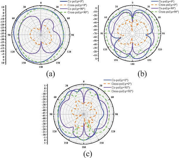
Figure 10 Simulated radiation patterns of the optimized single antenna (Antenna 3) at three representative frequencies: (a) 4.6 GHz, (b) 15.4 GHz, (c) 18.5 GHz. Solid lines: co-polarization; dashed lines: cross-polarization.
2.3 MIMO antenna design and analysis
The designed single antenna is rotated symmetrically around the center to form a four-element MIMO antenna configuration, as shown in Fig. 11 (a) (referred to as Antenna Model 4). To further reduce mutual coupling, an isolation structure consisting of a cross-shaped decoupling structure with hollow patterns and eight L-shaped branches is introduced between the antenna elements, as shown in Fig. 11 (b) (referred to as Antenna Model 5). In both configurations, the current distributions are obtained by exciting Port 1 while terminating Ports 2, 3, and 4 with matched loads.
Figure 12 presents the simulated S-parameters of Antenna Model 4 and Antenna Model 5, including the reflection coefficient (S11) and transmission coefficient (S12) curves for both configurations. For the reflection coefficient characteristics, without the isolation structure (Antenna Model 4), the resonant frequency shifts slightly due to mutual interference and impedance mismatch caused by the rotational replication of radiating elements. With the isolation structure added (Antenna Model 5), the resonant frequency is restored and the operating bandwidth remains essentially unchanged. For the isolation performance, without the isolation branches, the isolation between certain port pairs falls below 20 dB in some frequency bands. Although the DGS blocks most of the surface current, residual coupling still exists between the antenna elements. With the isolation structure added, the residual coupling current is further suppressed and the isolation is significantly improved to above 20 dB across the entire 3.36–21.91 GHz operating band. The effectiveness of this isolation structure is further confirmed by the measured S-parameter results of the fabricated MIMO antenna prototype presented in section 3.1 (Fig. 15), where S12 remains below 20 dB across the full operating band. The introduction of the isolation structure not only enhances isolation and reduces crosstalk, but also improves signal transmission capacity and spectrum utilization of the MIMO system.
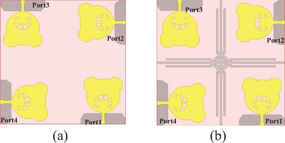
Figure 11 MIMO antenna design: (a) Antenna Model 4 and (b) Antenna Model 5.
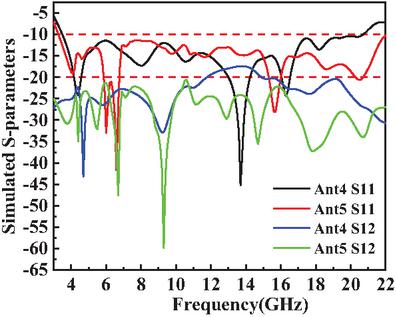
Figure 12 Simulated S-parameters before and after adding an isolated branch.
2.4 Antenna parameter analysis
During the antenna optimization process, the single-parameter scanning method was employed. By considering the positions of parameters within the antenna, the influence of each parameter on the return loss S11 was analyzed. Figure 13 illustrates the optimization results.
The first group consists of width-related parameters for the radiation patch. These parameters directly affect the resonant characteristics of the radiating element by altering its equivalent electrical length and reactance distribution. With W9 as an example, when the length increases from 1.5 mm to 2 mm, the resonant frequency of the low frequency band shifts slightly downward as the equivalent electrical length increases, and the S11 value within this band remains consistently below 10 dB. Meanwhile, due to the more balanced reactance distribution in the mid-frequency band, the fluctuation amplitude of S11 is significantly reduced. However, if the width is further increased to 3.5–4.0 mm, the resonant mode of the high-frequency band will be disturbed, causing a shift in resonant frequency. The matching performance degrades accordingly, with S11 rising above 10 dB. Accordingly, for balancing multi-band resonance and matching, the optimal width is identified as .
The second group comprises length-related parameters for the ground plane/isolation structure. These parameters indirectly influence antenna performance by regulating the current return path and resonant mode. With L6 as an example, when the length is less than 1.6 mm, the matching performance in the low-frequency band is excellent. However, the resonant mode in the mid-frequency band becomes unstable, leading to severe fluctuations in S11. When the length is set to 1.6 mm, the continuity between the resonant frequencies of the mid-frequency band and the low-frequency band is significantly improved, and the S11 value across the entire frequency band remains stably below 10 dB. If the length is further increased to more than 2.0 mm, changes in the current path will cause the resonant frequency of the high-frequency band to shift upward, which in turn leads to a noticeable rise in the S11 value. Hence, the optimal value for balancing resonance continuity and S11 performance is identified as .
The third group refers to width-related parameters at the interface between the radiation patch and the isolation structure. These parameters affect both the current distribution of the radiating element and the electromagnetic coupling between elements, thereby influencing resonance and matching. With W4 as an example, when the width ranges from 3 mm to 5 mm, the resonant frequency in the low-frequency band achieves good matching; however, due to coupling imbalance in the mid-to-high frequency band, the resonant frequencies are scattered and S11 fluctuates drastically. When the width is increased to 6 mm, the coupling in the mid-to-high frequency band tends to stabilize, the coverage range of resonant frequencies expands, and the S11 value within this range drops to below 10 dB. If the width is further increased to 7–8 mm, excessive coupling will cause a shift in the resonant mode of the high-frequency band, leading to an upward shift of the resonant frequency and a subsequent rise in the S11 value. Consequently, the optimal value for achieving multi-band resonance coverage and low S11 performance is confirmed as .
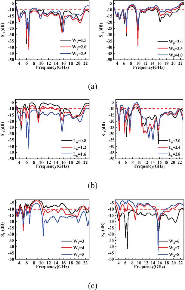
Figure 13 Effect of adjusted parameters on parameters: (a) , (b) , and (c) .
3 RESULTS AND DISCUSSION
3.1 S-parameters
The MIMO antenna was simulated using Ansys Electronics Desktop 2021 R2. To verify the antenna’s practical performance, the optimized model was fabricated into a prototype, with the finished prototype shown in Fig. 14 (a). The prototype was then measured using an Agilent N52235A vector network analyzer, and the measurement setup is illustrated in Fig. 14 (b). Owing to the structural symmetry of the orthogonal arrangement, ideally the reflection coefficients are identical across all ports, and the radiation patterns of all elements share the same shape with successive 90∘ rotation. For the coupling parameters, S12 and S13 are presented to represent the adjacent and diagonal coupling paths, respectively. Therefore, only the S-parameter results measured from Port 1 (S11, S12, and S13) are shown for brevity. Figure 15 shows that the antenna operates over a frequency range of 3.36–21.91 GHz, thereby achieving wide bandwidth coverage. Furthermore, within the UWB frequency band, both the S12 and S13 parameters remain consistently below 20 dB, indicating excellent isolation performance. While minor discrepancies are observed between the measured and simulated S11, S12, and S13 results, their overall trends are highly consistent, confirming stable wideband performance. These discrepancies are primarily attributed to the frequency-dependent insertion loss of the SMA connectors, fabrication tolerances in fine structural features such as the narrow slots and ear details of the bear-shaped patch, and the frequency-dependent dielectric properties of the FR4 substrate, which deviate from the nominal simulation value at higher frequencies.
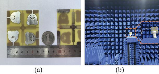
Figure 14 Proposed antenna: (a) antenna object and (b) antenna microwave darkroom measurement environment.
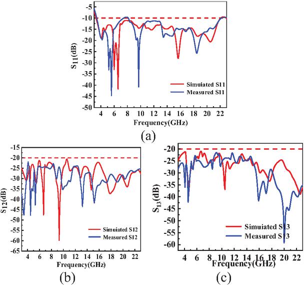
Figure 15 Simulated and measured S-parameters of the MIMO antenna: (a) S11, (b) S12, (c) S13.
3.2 Radiation properties
Figure 16 presents the measured 2-D radiation patterns of the proposed four-port UWB MIMO antenna at three representative frequencies (6.6 GHz, 15.4 GHz, and 20.5 GHz), covering the entire operating band. The measurements were carried out in a far-field anechoic chamber using a standard far-field measurement setup. During the measurement, one port was excited while the other three ports were terminated with matched loads. The gain distributions were recorded in the E-plane (, XOZ plane) and H-plane (, YOZ plane) over the angular range .
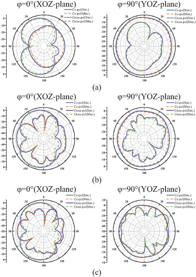
Figure 16 Modeled and measured radiation characteristics: (a) 6.6 GHz, (b) 15.4 GHz, and (c) 20.5 GHz.
At the low frequency of 6.6 GHz, the E-plane exhibits a typical dipole-like figure-of-eight pattern with main lobes directed at 0∘ and 180∘, while the H-plane shows good quasi-omnidirectional characteristics, which are beneficial for wide-angle radiation coverage. As the frequency increases to 15.4 GHz, due to the increased electrical size of the antenna at higher frequencies, the E-plane pattern exhibits noticeable ripples and subsidiary lobes, although the main radiation directions remain stable. The H-plane generally retains its quasi-omnidirectional behavior with slightly increased fluctuations. At 20.5 GHz, higher-order modes are excited, resulting in multi-lobed patterns with stronger angular variations. Nevertheless, the antenna still maintains stable radiation characteristics.
Regarding polarization purity, the antenna exhibits good cross-polarization suppression across the entire operating band. At 6.6 GHz, the cross-polarization level is below 15 dB in the main radiation directions, while at 15.4 GHz it remains below 18 dB. At 20.5 GHz, the cross-polarization level increases slightly but is still significantly lower than the co-polarized component, with a difference of approximately 15–20 dB in the main radiation directions. These results indicate good polarization discrimination throughout the operating band. Furthermore, at all measured frequencies, the simulated and measured co-polarization and cross-polarization patterns agree well, validating the effectiveness and practical radiation performance of the proposed antenna.
Figure 17 presents the peak gain and radiation efficiency of the optimized single antenna (Antenna 3) and the proposed four-port MIMO antenna (Antenna Model 5) across the operating band. As shown in Fig. 17 (a), the simulated peak gain of Antenna 3 ranges from 2.5 to 7.8 dBi, while that of Antenna Model 5 reaches 4.0–7.0 dBi with a maximum value of approximately 7.0 dBi. The measured peak gain of Antenna Model 5 generally follows the same trend as the simulation, with slight deviations attributed to fabrication tolerances and measurement uncertainties. The gain fluctuation at higher frequencies is mainly due to the excitation of higher-order modes and the increased electrical size of the antenna. As shown in Fig. 17 (b), the simulated radiation efficiency of both antennas remains above 72% throughout the entire operating band, with most frequencies maintaining efficiency above 80%. For Antenna Model 5, the measured radiation efficiency stays consistently above 78% across the operating band, matching the simulated trend well. The comparable efficiency between the single antenna and the MIMO antenna demonstrates that the proposed decoupling structures introduce only marginal additional conduction or dielectric losses. Overall, the measured gain results are in good agreement with the simulated data, validating the effectiveness of the proposed design.
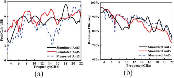
Figure 17 (a) Peak gain and (b) radiation efficiency of the optimized single antenna (Ant3) and MIMO Antenna (Ant5).
3.3 MIMO antenna performance
3.3.1 DG and ECC
The diversity characteristics and mutual coupling performance of MIMO antennas can be characterized by the envelope correlation coefficient (ECC). The ECC quantifies the spatial correlation between the far-field radiation patterns of different antenna elements, with lower values indicating better independence among the elements. The radiation pattern-based ECC is calculated using both the and components of the far-field electric field over the entire solid angle, assuming an isotropic propagation environment, as shown in equation (1) [4]. Diversity gain (DG) is a key metric that characterizes the degree of signal amplification or attenuation in MIMO systems, determined by equation (2) [4]. Typically, the ECC of MIMO antennas is required to be below 0.5 to meet the specifications for S-parameters (dB), radiation efficiency (%), and peak gain (dBi); furthermore, the closer the DG value is to 10, the more excellent the performance of the MIMO antenna. As illustrated in Fig. 18, the ECC of the proposed antenna is consistently below 0.005, and the DG approaches 10, demonstrating that it meets the requirements for communication applications within the 3.36–21.91 GHz band.
| (1) | |
| (2) |
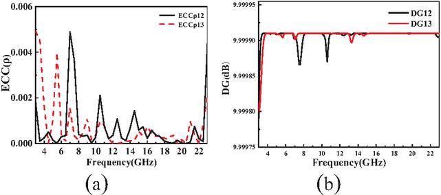
Figure 18 (a) ECC and (b) DG of the proposed antenna.
3.3.2 TARC
The total active reflection coefficient (TARC) is a metric used to evaluate the overall reflection performance of MIMO antennas, which comprehensively takes into account the reflected signals at all ports and the mutual coupling effects between antenna elements. Its core idea is to reflect the overall impedance matching efficiency of the antenna and the coupling degree between ports by quantifying the total reflection characteristics of the system under all-port excitation. Ideally, TARC should approach zero, which indicates that the antenna can efficiently absorb incident power and reduce reflection and mutual coupling interference. The TARC of this MIMO system can be calculated by the following equation [4]:
| (3) |
As shown in Fig. 19, in the frequency range of 3.36–21.91 GHz, the curves of TARC12 and TARC13 mostly remain at a relatively low decibel level. Among these, a large number of frequency bands are below 10 dB, and the performance in some regions is even better. This indicates that the reflection and mutual coupling effects between the ports of the proposed MIMO antenna are weak. It can not only absorb incident power more efficiently and reduce reflection loss, but also ensure different ports have good independence, which is conducive to improving the communication capacity and reliability of the MIMO system.
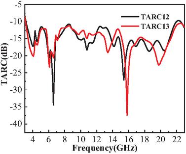
Figure 19 Simulation results of the TARC of the proposed antenna.
3.3.3 CCL
Channel capacity loss (CCL) is a key metric for evaluating the effective data transmission performance of MIMO communication systems, which quantifies the capacity degradation caused by mutual coupling between antenna elements. Its core idea is to reflect the impact of inter-port coupling on the system’s transmission efficiency by measuring the loss of available channel capacity. Ideally, the CCL should be as small as possible, which indicates that the antenna’s coupling effect has little influence on the channel capacity, thus ensuring efficient data transmission. The CCL of this MIMO system can be calculated by the following equation [4]:
| (4) |
where denotes the receiver’s correlation matrix, expressed as:
The elements of the matrix are defined as:
As shown in Fig. 20, within the operating frequency range of 3.36–21.91 GHz, the curves of CCL12 and CCL13 mostly maintain a relatively low level. Most frequency bands have CCL values below 0.1 bps/Hz, and some regions even approach 0.1 bps/Hz, which is far less than the reliable value of 0.4 bps/Hz. This result indicates that the mutual coupling between the ports of the proposed MIMO antenna has a minimal impact on the channel capacity, effectively reducing capacity loss. It not only enables the system to transmit data more efficiently but also enhances the communication reliability of the MIMO system, which is conducive to the practical application of the antenna in UWB communication scenarios.
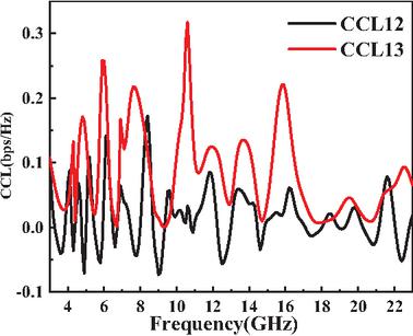
Figure 20 Simulation results of the CCL of the proposed antenna.
3.3.4 Pulse fidelity and group delay characteristics
Figure 21 (a) shows the group delay characteristics of the proposed four-element UWB MIMO antenna, corresponding to the transmission paths between Port 1 and Port 2 (Group Delay 12) as well as Port 1 and Port 3 (Group Delay 13). Both curves exhibit stable and flat performance across the entire operating band of 3.36–21.91 GHz, with group delay values ranging from approximately 0.2 to 1.0 ns and only minor, gradual fluctuations. No pronounced abrupt changes or severe oscillations are observed throughout the frequency range. To further quantify the impact of these characteristics on pulse distortion, the fidelity factor (FF) is calculated for the two paths, as shown in Fig. 21 (b). The FF, which measures the similarity between the input and output pulses, is a critical metric for UWB systems, with a minimum acceptable threshold of 0.9. Both paths exhibit FF values significantly above this threshold: the FF for the 12 path is approximately 0.962, while the FF for the 13 path reaches approximately 0.971. These results confirm that the flat group delay performance effectively mitigates frequency dispersion, avoiding excessive delay differences that would otherwise cause pulse broadening and signal distortion. The excellent timedomain performance ensures reliable signal integrity for UWB impulse-based communication and ranging applications.
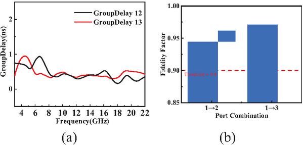
Figure 21 Time-domain performance of the proposed antenna: (a) group delay and (b) fidelity factor.
3.3.5 Comparative study
Table 2 provides a comparative analysis of the proposed antenna against existing designs with respect to key performance metrics, including size, operating bandwidth, isolation, number of ports, and ECC. Firstly, the proposed antenna achieves an operating bandwidth of 3.36–21.91 GHz, which exceeds that of most referenced designs (2.1–20 GHz [25] and 4.4–11.1 GHz [20]), enabling full coverage of the C/X/Ku bands. Secondly, its four-port configuration is more compact than larger four-port counterparts such as [24] and [25] () and, unlike two-port schemes [20], it does not compromise multi-stream transmission capability. Meanwhile, the antenna maintains full-band isolation greater than 20 dB, outperforming [26] (18 dB) and [27] (17 dB), and matching the isolation level of [28] while offering a wider bandwidth. The high isolation (25 dB) of [24] and [25] comes at the cost of a larger footprint. Finally, with an ECC of less than 0.006, the proposed antenna outperforms most designs [20, 24, 25], and is only slightly higher than that of [29] (0.004) while featuring a more compact size. Thus, the proposed antenna essentially achieves balanced optimization of various performance metrics, resolves common tradeoffs in existing designs, and meets the typical requirements for UWB MIMO antennas.
Table 2 Performance comparison of the proposed MIMO antenna with other works
| Ref. | Size (mm2) | Bandwidth (GHz) | Isolation (dB) | Port | ECC |
| [8] | 3–11 | 25 | 2 | 0.004 | |
| [16] | 3.1–10.6 | 31 | 2 | 0.035 | |
| [19] | 3–10.7 | 25 | 2 | 0.01 | |
| [20] | 3.4–8.25 | 25 | 4 | 0.01 | |
| [21] | 2.1–20 | 25 | 4 | 0.02 | |
| [22] | 2.8–13.3 | 18 | 4 | 0.06 | |
| [23] | 2.96–11.25 | 17 | 4 | 0.012 | |
| [24] | 3–11 | 20 | 4 | 0.02 | |
| [25] | 1–20 | 20 | 4 | 0.004 | |
| This Work | 3.36–21.91 | 20 | 4 | 0.005 |
4 CONCLUSION
This paper presents an innovative bear-shaped radiating element antenna for the miniaturization, high isolation, and wide bandwidth requirements of UWB MIMO antennas, where the radiating element is not merely a morphological innovation. Its irregular outline enriches the diversity of equivalent current paths, facilitates the cooperative excitation of multiple characteristic modes, and lays a structural foundation for UWB performance. Meanwhile, with CMA as the core theoretical guidance, the proposed configuration integrates DGS, a cross-shaped hollowed-out decoupling structure, and eight L-shaped matching stubs to form a systematic decoupling scheme, suppressing mutual coupling between elements from the perspective of physical mechanisms and overcoming the limitations of traditional trial-and-error approaches. Through the in-depth integration of structural optimization and theoretical guidance, the antenna achieves wideband coverage of 3.36–21.91 GHz with isolation exceeding 20 dB, and comprehensive advantages of high radiation efficiency and low ECC. It thereby provides an efficient and reliable antenna solution for advanced wireless communication scenarios with stringent requirements on bandwidth, isolation, and volume, such as V2X, autonomous driving positioning, and industrial IoT. Future work will focus on further miniaturizing the antenna without losing core performance to adapt to more compact terminal devices, and replacing traditional FR4 substrates with flexible substrates to expand its application potential in wearable devices.
ACKNOWLEDGMENT
This work was supported in part by the Natural Science Research Project of Anhui Educational Committee under Grant no. 2025AHGXZK31006, in part by The Research Foundation of Jiangsu Engineering Research Center for Bionics Control Technology and Equipment under No. FSKZ202503, and in part by the Fund of Anhui Mining Machinery and Electrical Equipment Coordination Innovation Center (Anhui University of Science and Technology) under grant No. KSJD202406.
REFERENCES
[1] K. S. Muttair, A. Z. G. Zahid, O. A. S. Al-Ani, A. M. Q. Al-Asadi, and M. F. Mosleh, “Antennas performance comparison of multi-bands for optimal outdoor and indoor environments wireless coverage,” Indonesian Journal of Electrical Engineering and Informatics (IJEEI), vol. 9, no. 4, pp. 846–858, 2021.
[2] B. Wu, X.-Y. Sun, H.-R. Zu, H.-H. Zhang, and T. Su, “Transparent ultrawideband halved coplanar Vivaldi antenna with metal mesh film,” IEEE Antennas Wireless Propag. Lett., vol. 21, pp. 2532–2536, 2022.
[3] J. F. Li, Q. X. Chu, Z. H. Li, and X. X. Xia, “Compact dual band-notched UWB MIMO antenna with high isolation,” IEEE Trans. Antennas Propag., vol. 61, pp. 4759–4766, 2013.
[4] M. S. Sharawi, “Printed multi-band MIMO antenna systems and their performance metrics [wireless corner],” IEEE Antennas Propag. Mag., vol. 55, no. 5, pp. 218–232, 2013.
[5] S. Kim, E. Visotsky, P. Moorut, K. Bechta, A. Ghosh, and C. Dietrich, “Coexistence of 5G with the incumbents in the 28 and 70 GHz bands,” IEEE J. Sel. Areas Commun., vol. 35, no. 6, pp. 1254–1268, 2017.
[6] J. H. Lee, J. S. Choi, and S. C. Kim, “Cell coverage analysis of 28 GHz millimeter wave in urban microcell environment using 3-D ray tracing,” IEEE Trans. Antennas Propag., vol. 66, no. 3, pp. 1479–1487, 2018.
[7] H. Ullah, S. Ur Rahman, Q. Cao, I. Khan, and H. Ullah, “Design of SWB MIMO antenna with extremely wideband isolation,” Electronics, vol. 9, no. 1, p. 194, 2020.
[8] L. Wang, Z. Du, H. Yang, R. Ma, Y. Zhao, X. Cui, and X. Xi, “Compact UWB MIMO antenna with high isolation using fence-type decoupling structure,” IEEE Antennas Wireless Propag. Lett., vol. 18, pp. 1641–1645, 2019.
[9] A. Fitri, U. Umaisaroh, and M. Alaydrus, “A novel parasitic EBG structure to enhance mutual coupling for 2.45 GHz MIMO antenna,” in 2022 International Conference on Radar, Antenna, Microwave, Electronics, and Telecommunications (ICRAMET), pp. 253–257, 2022.
[10] A. R. Vilenskiy, V. I. Litun, and K. V. Lyulyukin, “Wideband beam steering antenna array of printed cavity-backed elements with integrated EBG structure,” IEEE Antennas Wireless Propag. Lett., vol. 18, no. 2, pp. 245–249, Feb. 2019.
[11] S. Zhang and G. F. Pedersen, “Mutual coupling reduction for UWB MIMO antennas with a wideband neutralization line,” IEEE Antennas Wireless Propag. Lett., vol. 15, pp. 166–169, 2016.
[12] R. K. Garg, S. Singhal, M. V. Nair, and R. Tomar, “Wideband planar UWB MIMO antenna design with a leaf-shaped four-port,” IEEE Antennas Wireless Propag. Lett., vol. 13, pp. 1663–1666, 2014.
[13] H. C. Ye, C. Mao, L. L. Dai, and X. Y. Zhang, “Dual-band dual-polarized antenna and array with enhanced bandwidth for 5G millimeter-wave applications,” IEEE Antennas Wireless Propag. Lett., vol. 24, no. 7, pp. 1829–1833, July 2025.
[14] T. Vijetha and D. R. Krishna, “Dual band notch antenna for ultra wide band applications,” in 2022 IEEE Microwaves, Antennas, and Propagation Conference (MAPCON), pp. 1961–1965, 2022.
[15] S. Jayant, G. Srivastava, and S. Kumar, “Pattern diversity and isolation enhancement of UWB MIMO antenna based on characteristic modes for mobile terminals,” International Journal of Microwave and Wireless Technologies, pp. 793–804, 2023.
[16] S. Zhang and G. F. Pedersen, “Mutual coupling reduction for UWB MIMO antennas with a wideband neutralization line,” IEEE Antennas Wireless Propag. Lett., vol. 15, pp. 166–169, 2016.
[17] M. V. Yadav and S. Baudha, “A miniaturized printed antenna with extended circular patch and partial ground plane for UWB applications,” Wireless Personal Communications, vol. 116, no. 1, pp. 311–323, 2020.
[18] R. I. Nawar, A. M. Abdelhady, and A. Y. Hassan, “High performance circularly polarized quad-elements for 5G wireless communications,” Arabian Journal for Science and Engineering, pp. 1–18, 2025.
[19] W. H. Chen, L. H. Ye, K. Ding, F. Jiang, and D.-L. Wu, “A broadband circularly polarized antenna using characteristic mode analysis,” IEEE Trans. Antennas Propag., vol. 72, no. 12, pp. 9143–9151, 2024.
[20] C. Fu, C. Feng, W. Chu, Y. Yue, X. Zhu, and W. Gu, “Design of a broadband high-gain omnidirectional antenna with low cross polarization based on characteristic mode theory,” IEEE Antennas Wireless Propag. Lett., vol. 21, no. 9, pp. 1747–1751, 2022.
[21] M. Ren, J. Li, H. Zhao, and C. Xia, “A novel triband circularly polarized metasurface antenna based on characteristic mode analysis,” IEEE Antennas Wireless Propag. Lett., vol. 23, no. 11, pp. 3817–3821, 2024.
[22] Z. Zhan, W. Huang, R. Deng, and B. Li, “Compact dual polarized antenna with wide band and high isolation using characteristic mode analysis,” Progress in Electromagnetics Research C, vol. 142, pp. 95–106, 2024.
[23] S. Modak and T. Khan, “A slotted UWB-MIMO antenna with quadruple band-notch characteristics using mushroom EBG structure,” AEU–International Journal of Electronics and Communications, vol. 134, p. 153673, 2021.
[24] A. Ghosh, A. Ghosh, and J. Kumar, “Circularly polarized wideband quad-element MIMO antenna with improved axial ratio bandwidth and mutual coupling,” IEEE Antennas Wireless Propag. Lett., vol. 23, pp. 4718–4722, 2024.
[25] V. S. D. Rekha, P. Pardhasaradhi, B. T. P. Madhav, and Y. U. Devi, “Dual band notched orthogonal 4-element MIMO antenna with isolation for UWB applications,” IEEE Access, vol. 8, pp. 145871–145880, 2020.
[26] S. Kumar, G. H. Lee, D. H. Kim, W. Mohyuddin, H. C. Choi, and K. W. Kim, “Multiple-input-multiple-output/diversity antenna with dual band-notched characteristics for ultra-wideband applications,” Microwave Opt. Technol. Lett., vol. 62, no. 1, pp. 336–345, 2020.
[27] X. Lu, S. Linghu, F. Pang, and T. Zhang, “A miniaturized ultra-wideband MIMO antenna design with dual-band notched characteristics,” Progress in Electromagnetics Research M, vol. 115, pp. 45–58, 2023.
[28] S. S. Ahmed, B. Khan, M. Manzoor, M. Souri, M. Alibakhshikenari, M. F. Darsinos, and E. Falcone, “A compact CPW-fed ultra-wideband multi-input-multi-output (MIMO) antenna for wireless communication networks,” IEEE Access, vol. 10, pp. 25278–25289, 2022.
[29] Y. Yao, Y. Shao, J. Zhang, and J. Zhang, “A transparent antenna using metal mesh for UWB MIMO applications,” IEEE Trans. Antennas Propag., vol. 71, pp. 3836–3844, 2023.
BIOGRAPHIES

Xiaoyan Wei received the B.E. degree from Anhui University of Science and Technology, China, in 2024. She is currently pursuing the M.S. degree at Anhui University of Science and Technology. Her current research interests include the theory and design of UWB MIMO antenna based on characteristic mode analysis.

Zhonggen Wang received the Ph.D. degree in electromagnetic field and microwave technique from the Anhui University of China (AHU), Hefei, P. R. China, in 2014. Since 2014, he has been with the School of Electrical and Information Engineering, Anhui University of Science and Technology. His research interests include computational electromagnetics, array antennas, and reflect arrays.

Wenyan Nie is a professor at Huainan Normal University, China. She received the B.S. and M.S degrees from Anhui University of Science and Technology in 2007 and 2012, respectively. Her research interests include computational electromagnetic methods, antenna theory and design.

Chenlu Li received the Ph.D. degree from Anhui University, China, in 2017. She is currently working at Hefei Normal University. Her research interests include electromagnetic scattering analysis of targets and filtering antenna design.

Zhengting Zhang received the B.E. degree from Anhui University of Science and Technology, China, in 2024. He is currently pursuing the M.S degree at Anhui University of Science and Technology. His current research interests include the design and research of miniaturized antennas for 5G Sub-6 GHz applications.
ACES JOURNAL, Vol. 41, No. 7, 621–634
DOI: 10.13052/2026.ACES.J.410703
© 2026 River Publishers