A Full-Wave Method for Radar Cross-Section Analysis with Locally Generated Structured Electromagnetic Waves
Matthew J. Dodd1, Kobe Prior1, Joseph E. Diener1, Veysel Demir2, and Atef Z. Elsherbeni1
1Department of Electrical Engineering
Colorado School of Mines, Golden, CO 80401, USA
mdodd@mines.edu, kdprior@mines.edu, jdiener@mines.edu, aelsherb@mines.edu
2Department of Electrical Engineering
Northern Illinois University, DeKalb, IL 60115, USA
vdemir@niu.edu
Submitted On: December 23, 2025; Accepted On: April 01, 2026
Abstract
This work presents a full-wave numerical method for simulating the radar cross-section (RCS) of targets illuminated by structured electromagnetic waves generated by physically realizable sources embedded within the simulation domain. The proposed framework enables RCS prediction using practical excitation mechanisms, such as antenna arrays, rather than idealized incident fields. To demonstrate the approach, we compute the RCS of several canonical targets under illumination by an orbital angular momentum (OAM) vortex wave produced by a uniform circular array (UCA) of dipole antennas. The simulated results reveal distinctive scattering behaviors and increased RCS diversity associated with OAM-based structured wave excitation. The methodology establishes a foundation for future studies of target scattering under a broad range of structured electromagnetic fields and source configurations.
Index Terms: Radar cross-sections, microwave orbital angular momentum, finite difference time domain (FDTD), method of moments (MoM).
I. INTRODUCTION
Structured electromagnetic waves constitute a class of field distributions characterized by spatially varying phase and amplitude profiles in the far field. Common examples include Laguerre-Gaussian (LG) and Hermite-Gaussian (HG) modes, which exhibit nontrivial wavefront structures and unique propagation characteristics. In this work, we focus on structured waves carrying orbital angular momentum (OAM), often referred to as vortex beams. The electric field of an OAM mode can be expressed as
| (1) |
where is the azimuthal mode index and is the wavenumber.
A number of prior studies have investigated the radar cross-section (RCS) diversity associated with OAM-wave illumination. Physical optics (PO)-based techniques have been widely used to model scattering from electrically large objects under OAM excitation [1, 2, 3, 4, 5, 6], and several experimental measurements of OAMinduced RCS variations have been reported for canonical and complex targets [1, 7, 8, 9]. Additional studies have examined reflection and refraction of OAM waves from dielectric and perfectly conducting slabs [10]. While PO methods offer computational efficiency for large scatterers, they inherently neglect important mechanisms such as edge diffraction, creeping waves, and higher-order interactions
Full-wave electromagnetic techniques-including the method of moments (MoM) and the finitedifference time-domain (FDTD) method-provide a more rigorous alternative, yielding accurate scattered fields for objects of arbitrary size and geometry. Prior full-wave studies involving OAM illumination have typically injected vortex beams using analytical field expressions prescribed at a domain boundary or source plane [11, 12]. Mie theory has also been used to analyze LG-mode scattering from spherical objects [13]. In [14], OAM excitation generated by idealized Hertzian dipoles was examined within a PO framework for PEC targets.
In contrast to these approaches, this work develops a full-wave simulation methodology in which the structured wave is generated by a physical source located inside the simulation domain. Specifically, we model an OAM beam produced by a uniform circular array (UCA) of dipole antennas, where each element is excited with a phase proportional to its azimuthal position of the array elements consistent with (1). This approach enables realistic modeling of structured-wave illumination from practical antenna architecture. Because the UCA radiates directly into the far field, the total computed fields contain contributions from both the source and the target scatterer. To analyze the RCS, we therefore introduce a systematic procedure for separating the scattered field from the directly radiated field. Another challenge arises in defining RCS for structured waves. Traditional RCS definitions assume plane-wave illumination with uniform incident power density (). Structured waves violate this assumption due to their inherently nonuniform spatial distributions. Accordingly, we adopt the generalized RCS definition
| (2) |
where is the average incident power density computed over a designated capture plane of area . This formulation enables consistent comparison between scattering under OAM illumination and traditional plane-wave excitation, similar to the normalization approach in [12]. It is important to note that the RCS is, in general, a function of the transmit and received polarization. The received polarization components are referred to by spherical coordinate unit vectors and , or the total . The results m presented are for an incident polarization in the +y direction (-component in YZ plane).
The remainder of this paper is organized as follows. Section 2 presents the methodology for generating OAM excitation using an embedded antenna array and for isolating the scattered field in full-wave simulations. Section 3 provides numerical results illustrating the RCS of canonical PEC objects under OAM illumination. Conclusions and potential extensions to other structured-wave sources are discussed in section 4.
II. METHOD
In full-wave electromagnetic simulations, the radiated far fields are computed from the currents induced by the excitation sources. In FDTD simulations, these far fields are obtained from the simulated near fields via the surface equivalence theorem [15]. A fictitious closed surface is placed around the radiating and scattering structures, and equivalent electric and magnetic surface currents representing the radiated fields are given by
| (3) | ||
| (4) |
where are the magnetic fields on the surface, are the electric fields, and is the unit normal vector to the surface.
When both antennas and scatterers are present inside the same computational domain, the equivalent surface currents naturally contain contributions from both the antenna radiation and the object’s scattered response. To isolate the scattered fields, we introduce a two-step simulation procedure, illustrated in Fig. 1.
1. Step 1: Simulate the full configuration containing the antenna array and the scatterer. Extract the total fictitious currents .
2. Step 2: Remove the scatterer and repeat the simulation using the same excitation. The resulting fictitious currents () represent the incident fields due solely to the antenna. A fluxcapture plane of area , aligned with the projected area of the scatterer, is used to compute the average incident power density which is required to normalize the RCS.
The scattered-field equivalent currents are then obtained by subtraction:
| (5) | |
| (6) |
The scattered far fields are computed using the standard radiation integrals with vector potentials [15]:
| (7) | |
| (8) |
Substituting the resulting scattered fields into the generalized RCS definition in (2) yields the desired bistatic RCS. The two RCS polarization components are
| (9) | ||
| (10) |
where is the wavenumber and is the free space impedance.
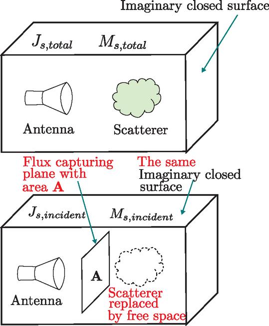
Figure 1 (Top) The first simulation step in the process contains both the local sources and the scatterer inside an imaginary closed surface. (Bottom) The second step removes the scatterer from the domain and includes a flux capture plane for incident power on the scatterer.
Throughout this work, we report the bistatic RCS for the case where the incident beam propagates along the +z direction with back and forward scattering directions correspond to and , respectively. This coordinate convention is the spherical coordinate system for antenna far field patterns. The observation direction , has an elevation angle that is measured from the +z axis and an azimuth angle that is measured from the +x axis as shown in Fig. 2.
Both the MoM framework of [16] and the FDTD solver of [17] are used. In MoM, the equivalent twostep subtraction process is applied in the far field rather than at the equivalent surface, i.e. which requires twice the number of far-field evaluations but is otherwise equivalent.
III. RESULTS
To validate the local-source RCS methodology, we first analyze a configuration where the scatterer is placed in the far field of a half-wavelength dipole antenna. At sufficiently large distance, the dipole radiation approximates a plane wave, enabling comparison with standard plane-wave RCS results obtained from full-wave simulations. Simulations are performed for both a PEC sphere and a PEC square plate at 8.75 GHz.
The far-field distance is computed as
| (11) |
where is the diameter of the radiating structure. For the validation study, the PEC sphere with diameter equal to is placed at a distance 60 times to ensure an excellent plane-wave approximation (Fig. 2). The RCS results appear in Fig. 3 and show excellent agreement between the local-source method and the conventional plane-wave RCS.
A similar comparison is made for the PEC plate shown in Fig. 4. Again, the RCS computed using the proposed two-step method matches the plane-wave RCS exactly as seen in Fig. 5, confirming the correctness of the field-separation procedure.
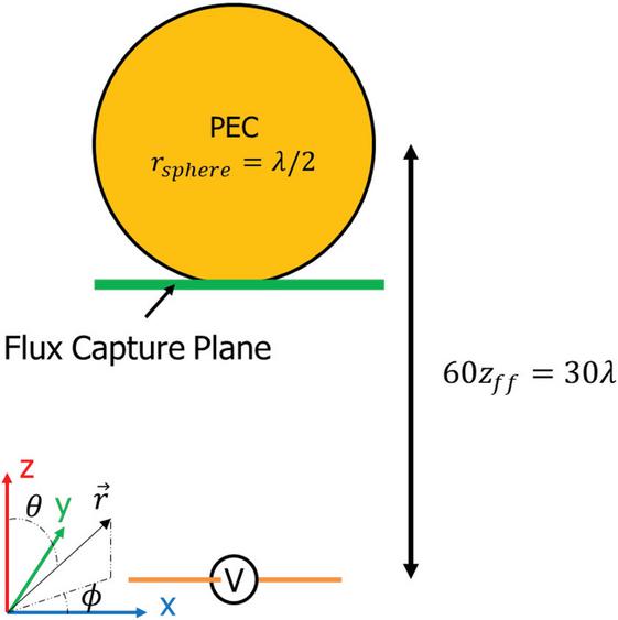
Figure 2 Simulation scenario to approximate a linearly polarized plane wave incident on a PEC sphere. The diameter of the sphere is one wavelength. The coordinate axis shows the spherical coordinate convention used to define the observation angles and for an observation direction towards the vector . The origin of the coordinates system is physically located at the center of the dipole source; however, it is offset in the figure for clarity.
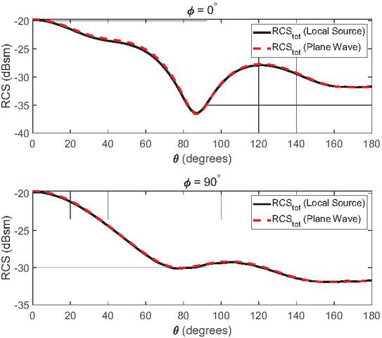
Figure 3 RCS computed by the local source method for a PEC sphere compared to the traditional plane wave RCS.
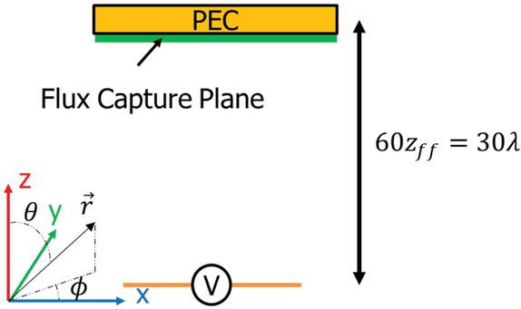
Figure 4 Simulation scenario to approximate a linearly polarized plane wave incident on a PEC plate. The width and length of the plate in the x–y plane are one wavelength. The origin of the coordinates system is physically located at the center of the dipole source; however, it is offset in the figure for clarity.
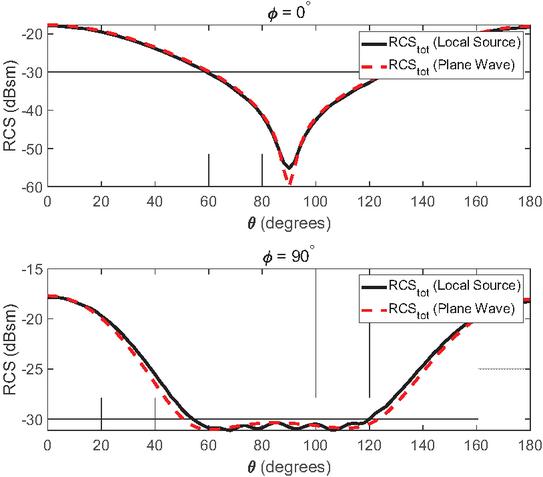
Figure 5 RCS computed by the local source method for a PEC plate compared to the traditional plane wave RCS.
A. PEC sphere RCS under OAM modes
We next examine RCS under OAM illumination. Structured waves are generated by a UCA of eight halfwavelength dipoles arranged with radius 17 mm (approximately at 8.75 GHz). The UCA is mounted 9 mm above a circular PEC reflector (radius 58.5 mm) to achieve unidirectional radiation (Fig. 6). Each OAM mode with index is synthesized by assigning element phases proportional to azimuthal angle as in (1).
Because OAM beams exhibit mode-dependent angular radiation maxima, the scatterer is repositioned for each mode so that it lies along the direction of maximum radiated power of the mode, ensuring consistent illumination across modes and accurate comparison with the plane wave RCS, as well as comparison between modes. Sample radiation patterns for modes , and 2 are shown in Fig. 7.
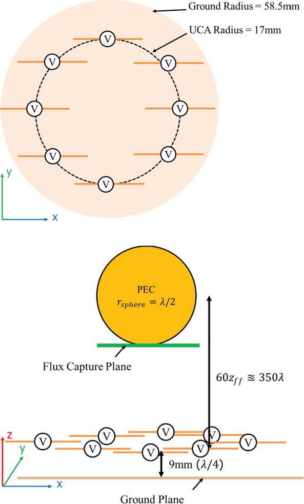
Figure 6 Geometry of the UCA shown from a top-down view (top) and from a side on view (bottom). The UCA consists of eight half wavelength dipole elements arranged in a circle above a PEC ground plane acting as a reflector. All dipole antennas are at the same height from the ground reflector but shown here at different heights for clarity. The origin of the coordinates system is physically located at the center of the ground plane; however, it is offset in the figure for clarity.
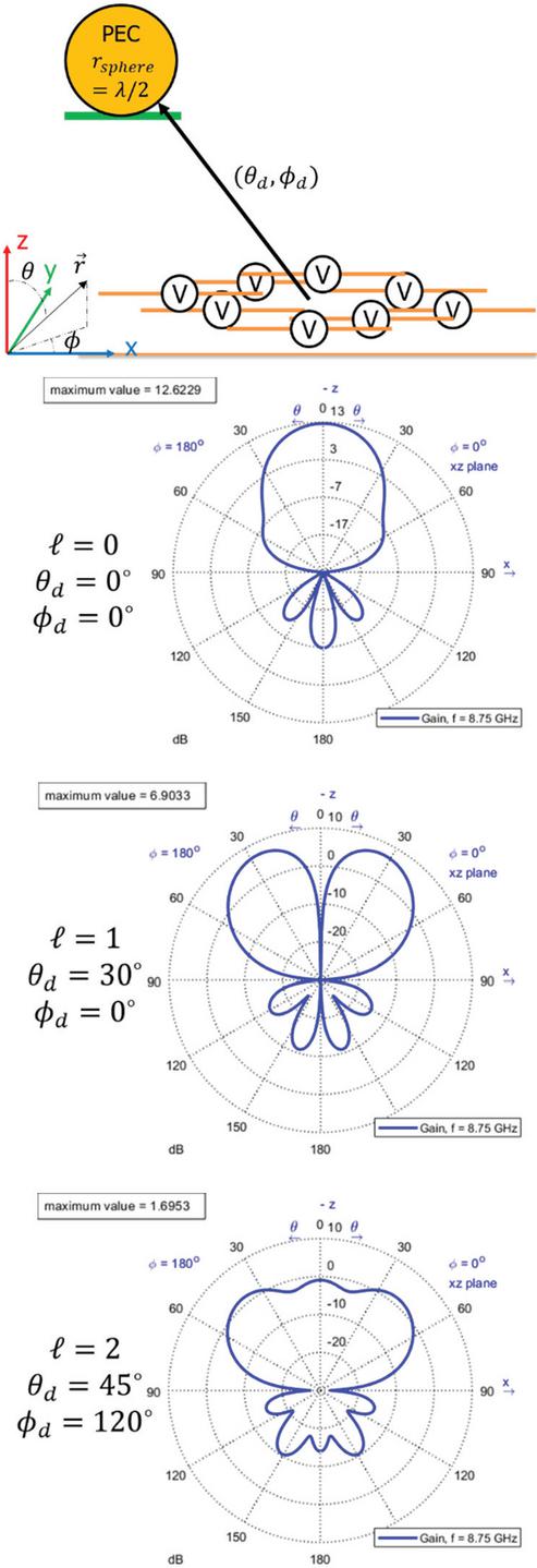
Figure 7 Geometry of the scattering simulations, with the target object located in the direction of maximum radiation, () as shown (top). The far field radiation patterns of the UCA for modes , and 2 with annotations for the direction of maximum radiation identified. All dipole antennas are at the same height from the ground reflector but shown here at different heights for clarity. The origin of the coordinates system is physically located at the center of the ground plane; however, it is offset in the figure for clarity.
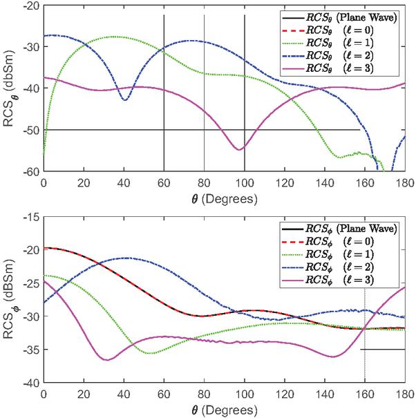
Figure 8 The bistatic RCS of the PEC sphere for modes in the plane for the -polarized component (top) and -polarized component (bottom).
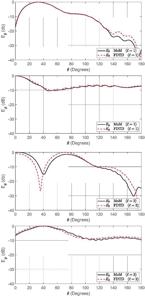
Figure 9 Normalized scattered field comparison for a PEC sphere between MoM and FDTD simulation methods. The results for are shown for the polarized (top) and -polarized (second from top) components of the scattered electric field. The same results for are shown for the -polarized (third from top) and -polarized (bottom) components.
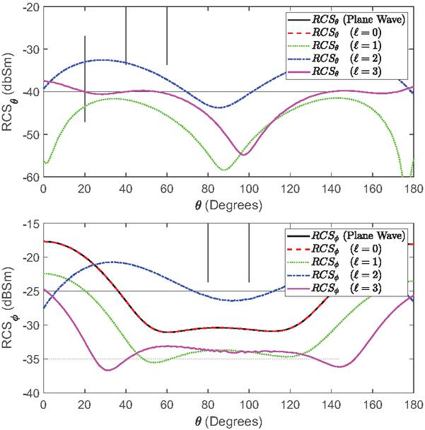
Figure 10 The bistatic RCS of the PEC plate for modes in the plane. The -polarized component (top) and the -polarized component (bottom).
Far field bistatic RCS patterns for the PEC sphere are shown in Fig. 8 for the elevation plane where and compared with the other modes as well as a plane wave on the same axis. For all results in this section, both the - and -polarized components of the RCS are presented separately. These polarization components are aligned with the spherical coordinate unit vectors. In the cartesian YZ plane, where or , the -polarization vector is pointing towards x or x direction respectively. The polarization vector is pointing towards y when , is pointing towards z when , and is pointing towards y when . This description applies to all polarized RCS calculations presented here. In the mode, the -polarized component is a very close approximation of a plane wave. It is notable that the polarized scattering component is higher magnitude for and for and at for modes, indicating an RCS diversity for the higher order OAM mode illuminating beams even in the co-polarized scattered fields.
Another significant characteristic of the sphere scattering results is the significant increase in the cross polarized -component of the scattered fields for all modes . The cross polarized component is nonexistent in the plane wave and modes, indicating a strong diversity induced by the OAM wave even for a rotationally symmetric scattering target such as the PEC sphere.
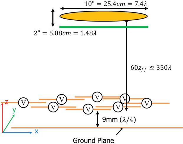
Figure 11 The PEC ogive is placed at 60 times the farfield distance above the UCA. The dimensions of the ogive are defined according to the standardized model used in RCS literature [18]. The origin of the coordinates system is physically located at the center of the ground plane; however, it is offset in the figure for clarity.
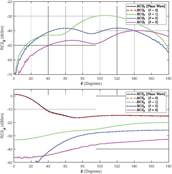
Figure 12 The bistatic RCS of the PEC ogive is calculated for modes . The plane is compared between modes and to a plane wave for the -polarized component (top) and -polarized component (bottom).
To further validate the method, scattered fields (not RCS) computed using MoM and FDTD are compared with the sphere moved to a distance of mm. The FDTD domain contains 64 million cells and is run for 15,000 steps; MoM requires only discretization of the sphere and antenna (2362 edges). The normalized scattered fields for are shown in Fig. 9 and exhibit good agreement. Small deviations occur primarily in cross-polarized components where field magnitudes are low and numerical precision is limited. When computing simulations for a single frequency with only PEC objects in the domain, the MoM is typically more efficient. However, many applications will require dielectric objects and wideband frequency simulation which reduces the efficiency of the MoM solution. In these applications, the FDTD computation is more efficient.
B. PEC plate RCS under OAM modes
The next canonical object used as a scattering target is the PEC plate. The PEC plate has a square cross-section with length and width equal to one wavelength at 8.75 GHz. The same simulation configurations that were used for the PEC sphere are repeated for the PEC plate. The RCS results are presented in Fig. 10 in the plane. The PEC plate RCS values are improved for the mode for the co-polarized -component while other modes follow a similar pattern to the plane wave but are lower in magnitude. As with the sphere, significant increases appear in the cross-polarized -component for all , again demonstrating OAM-induced polarization conversion.
C. PEC ogive RCS under OAM modes
The ogive is a commonly used object for RCS studies with standardized dimensions [18]. The simulation configuration is shown for a PEC ogive in Fig. 11. The corresponding RCS results are shown in Fig. 12 indicating that, unlike the sphere and plate, the ogive does not exhibit increased co-polarized scattering for OAM modes. However, a substantial increase in the cross-polarized component is again observed for all modes, suggesting that OAM-induced polarization conversion persists across geometrically distinct canonical scatterers.
IV. CONCLUSION
This work presents a general method for computing the scattered fields and radar cross-section of objects illuminated by structured electromagnetic waves generated by sources embedded within the simulation domain. This method is applicable to both FDTD and MoM solvers and provides a practical two-step procedure for isolating scattered fields from direct antenna radiation.
The approach is validated by comparing localsource RCS results with traditional plane-wave RCS for canonical PEC targets, showing excellent agreement. We then apply the method to OAM illumination produced by a realistic uniform circular dipole array. Across a range of canonical objects including a sphere, plate, and ogive we observe significant increases in cross-polarized scattering for OAM modes relative to plane waves. In some cases, increases in copolarized side-scattering are also observed.
These results demonstrate the RCS diversity achievable through structured-wave excitation and illustrate the capability of the proposed method to simulate realistic OAM sources. The framework provides a foundation for future work involving more general structured-wave excitations, complex scatterers, and advanced antenna architectures.
ACKNOWLEDGMENT
This work is sponsored by the Defense Advanced Research Projects Agency (DARPA) under Agreement No. HR00112590137.
REFERENCES
[1] Z. Wu, T. Qu, J. Wu, Z. Wu, L. Yang, and X. Li, “Scattering of electromagnetic waves with orbital angular momentum on metallic sphere,” IEEE Antennas Wirel. Propag. Lett., vol. 19, no. 8, pp. 1365–1369, Aug. 2020.
[2] M. Sun, S. Liu, L. Guo, and W. Pan, “Scattering of arbitrarily incident Laguerre–Gaussian vortex electromagnetic beams by electrically large-scaled complex targets,” JOSA A, vol. 40, no. 3, pp. 502–509, Mar. 2023.
[3] K. Liu, Y. Gao, X. Li, and Y. Cheng, “Target scattering characteristics for OAM-based radar,” AIP Adv., vol. 8, no. 2, p. 025002, Feb. 2018.
[4] Z. Wu, J. Wu, H. Li, T. Qu, X. Meng, Q. Xu, Z. Wu, J. Bai, L. Yang, L. Gong, and Y. Yun, “Integrated physical optics for calculating electric-large metallic sphere scattering irradiated by vortex wave in microwave frequency band,” IEEE Antennas Wirel. Propag. Lett., vol. 21, no. 6, pp. 1288-1292, June 2022.
[5] M. Arfan, A. Ghaffar, M. A. S. Alkanhal, M. Y. Naz, A. H. Alqahtani, and Y. Khan, “Orbital angular momentum wave scattering from perfect electromagnetic conductor (PEMC) sphere,” Optik, vol. 253, p. 168562, Mar. 2022.
[6] Z. Wu, J. Wu, T. Qu, Z. Wu, Q. Xu, H. Li, L. Yang, X. Meng, and J. Bai, “Scattering characteristics of an electrically-large aircraft object illuminated by Bessel vortex beams,” IEEE Access, vol. 10, pp. 126023–126029, 2022.
[7] X. Bu, X. Liang, Z. Zhang, L. Chen, H. Tang, and Z. Zeng, “Scattering characteristics of vortex electromagnetic waves for a wedge,” in 2018 Progress in Electromagnetics Research Symposium (PIERS-Toyama), pp. 801–804, Aug. 2018.
[8] C. Zhang, D. Chen, and X. Jiang, “RCS diversity of electromagnetic wave carrying orbital angular momentum,” Sci. Rep., vol. 7, no. 1, p. 15412, Nov. 2017.
[9] X. Bu, Z. Zhang, X. Liang, Z. Zeng, L. Chen, and H. Tang, “Scattering characteristics of vortex electromagnetic waves for typical targets,” in 2018 Asia-Pacific Microwave Conference (APMC), pp. 648–650, Nov. 2018.
[10] Y. Yao, X. Liang, M. Zhu, W. Zhu, J. Geng, and R. Jin, “Analysis and experiments on reflection and refraction of orbital angular momentum waves,” IEEE Trans. Antennas Propag., vol. 67, no. 4, pp. 2085–2094, Apr. 2019.
[11] W. Hanfei, Y. Xiaoli, Z. Zhaoyuan, and W. Xinhong, “Study on single particle scattering characteristics of OAM light based on finite-difference time-domain method,” in 2023 IEEE 6th International Conference on Electronics and Communication Engineering (ICECE), pp. 44–48, Dec. 2023.
[12] W. Sun, Y. Hu, C. Weimer, K. Ayers, R. R. Baize, and T. Lee, “A FDTD solution of scattering of laser beam with orbital angular momentum by dielectric particles: Far-field characteristics,” J. Quant. Spectrosc. Radiat. Transf., vol. 188, pp. 200–213, Feb. 2017.
[13] X. Zambrana-Puyalto and G. Molina-Terriza, “The role of the angular momentum of light in Mie scattering. Excitation of dielectric spheres with Laguerre–Gaussian modes,” J. Quant. Spectrosc. Radiat. Transf., vol. 126, pp. 50–55, Sep. 2013.
[14] K. Liu, H. Liu, W. E. I. Sha, Y. Cheng, and H. Wang, “Backward scattering of electrically large standard objects illuminated by OAM beams,” IEEE Antennas Wirel. Propag. Lett., vol. 19, no. 7, pp. 1167–1171, July 2020.
[15] A. Z. Elsherbeni and V. Demir, The Finite-Difference Time-Domain Method for Electromagnetics with Matlab Simulations, 3rd ed. Edison, NJ: SciTech Publishing Inc. an Imprint of the IET, 2016.
[16] FEKO. Altair Engineering, Inc. Available: www.altair.com/feko.
[17] V. Demir and A. Z. Elsherbeni. (Aug. 2022). Computational Electromagnetics Simulator (CEMS) [Online]. Available: veysdemir@gmail.com.
[18] A. C. Woo, H. T. G. Wang, M. J. Schuh, and M. L. Sanders, “EM programmer’s notebook-benchmark radar targets for the validation of computational electromagnetics programs,” IEEE Antennas Propag. Mag., vol. 35, no. 1, pp. 84–89, Feb. 1993.
BIOGRAPHIES

Matthew J. Dodd received his B.S. degree in Materials Science and Engineering from UWMadison, Madison, WI, USA, in 2018. He received his M.S. degree in Electrical Engineering from Colorado School of Mines, Golden, CO, in 2024 and is currently pursuing the Ph.D. in Electrical Engineering under Atef Elsherbeni. His research interests include optimization methods for electromagnetics, metamaterials, and phased array antennas.

Kobe Prior is pursuing the combined B.S. and M.S. degrees from Colorado School of Mines, Golden, CO, USA. His main research interests are antenna design, computational electromagnetics, structured electromagnetic waves, including orbital angular momentum (OAM) modes, phased array synthesis, and experimental characterization of scattering phenomena.

Joseph E. Diener obtained his M.S. degree in Electrical Engineering at Colorado School of Mines, Golden, CO, USA, and is currently pursuing his Ph.D. in Electrical Engineering under Atef Elsherbeni. His research interests include FDTD methods, GPU acceleration, genetic algorithms, antennas, active and passive circuits, and phased array systems.

Veysel Demir is an Associate Professor at the Department of Electrical Engineering at Northern Illinois University, USA. He received his Bachelor of Science degree in Electrical Engineering from Middle East Technical University, Ankara, Turkey, in 1997. He studied at Syracuse University, New York, where he received both a Master of Science and Doctor of Philosophy degrees in Electrical Engineering in 2002 and 2004, respectively. During his graduate studies, he worked as a Research Assistant for Sonnet Software, Inc., Liverpool, New York. He worked as a visiting Research Scholar in the Department of Electrical Engineering at the University of Mississippi from 2004 to 2007. He joined Northern Illinois University in August 2007 and served as an Assistant Professor until August 2014. He has been serving as an Associate Professor since then.

Atef Z. Elsherbeni received his Ph.D. degree in Electrical Engineering from Manitoba University, Winnipeg, Manitoba, Canada, in 1987. He started his engineering career as a part time Software and System Design Engineer from March 1980 to December 1982 at the Automated Data System Center, Cairo, Egypt. From January to August 1987, he was a Post-Doctoral Fellow at Manitoba University. Elsherbeni joined the faculty at the University of Mississippi in August 1987 as an Assistant Professor of Electrical Engineering and progressed to the full professor and the Associate Dean of the College of Engineering for Research and Graduate Programs. He then joined the Electrical Engineering and Computer Science (EECS) Department at Colorado School of Mines in August 2013. Elsherbeni is an IEEE Life Fellow and ACES Fellow. He is the Editor-in-Chief for Applied Computational Electromagnetics Society (ACES) Journal, and a past Associate Editor to the Radio Science Journal. He was the Chair of the Engineering and Physics Division of the Mississippi Academy of Science, the Chair of the Educational Activity Committee for IEEE Region 3 Section, and the past President of ACES Society. He received the 2023 IEEE APS Harington-Mittra Award for his contribution to computational electromagnetics with hardware acceleration and the ACES 2025 Computational Electromagnetics Award.
ACES JOURNAL, Vol. 41, No. 3, 207–215
DOI: 10.13052/2026.ACES.J.410302
© 2026 River Publishers