Synthesis and Design of a Wideband Filtering Impedance Transformer and its Application as a Power Divider
Haili Zhang1, 2, Zhenzhong Chen1, and Taijun Liu1*
1Faculty of Electrical Engineering and Computer Science Ningbo University, Ningbo 315210, China 158936225@qq.com, liutaijun@nbu.edu.cn
2Institute of IOT Application Technology Zhejiang Fashion Institute of Technology, Ningbo 315211, China 158936225@qq.com
*Corresponding Author
Submitted On: December 29, 2025; Accepted On: March 18, 2026
ABSTRACT
In this paper, two classes of impedance transformers with wide operating bandwidth are presented. The impedance parameters can be directly determined based on the specified impedance transformation ratio, fractional bandwidth (FBW), and in-band return loss () requirements. To validate the proposed method, an impedance transformer is designed at the center frequency of 2.4 GHz and an impedance-transforming ratio of 0.5. The filtering impedance transformer with FBW 90% and is fabricated and measured, validating the theoretical prediction. Furthermore, to demonstrate its application potential, the second impedance transformer is employed to realize a filtering power divider with wide operating bandwidth and enhanced isolation bandwidth.
Keywords: Filtering transformer, impedance transformer, isolation bandwidth, synthesis method, wideband power divider..
1 INTRODUCTION
An impedance transformer is a fundamental component in the design of radio frequency (RF) and microwave systems, critical to ensuring maximum power transfer and minimizing signal reflection between components with different characteristic impedances. Conventional impedance matching networks, such as transformers, are widely used because of their simplicity and effectiveness at a single frequency. However, their inherent narrowband characteristics limit their application in modern wideband communication systems, such as 5G and ultra-wideband, where broad bandwidth and a wide range of impedance transformer ratios are increasingly demanded [1, 2, 3].
To overcome the bandwidth limitation, multi-section impedance transformers have been proposed [4, 5]. These approaches can achieve wider bandwidth, but these designs typically lack frequency selectivity. Consequently, the integration of filtering response into impedance transformers has emerged as a promising direction, enabling circuits that perform simultaneous impedance transformation and bandpass filtering. For instance, in [6], a broadband impedance transforming network composed of cascaded transmission lines and short-circuited stubs is proposed, achieving an impedance transformation from to with a fractional bandwidth (FBW) of 77.8%. Compared to conventional transmission lines, coupled lines offer additional degrees of freedom for design control, including even-/odd-mode characteristic impedances and loading effects at both the through and coupled ports. This offers greater flexibility in the design of wideband impedance transformers [7, 8]. In summary, although the aforementioned methods significantly expand the bandwidth of impedance transformation networks, the achievable impedance ratio remains constrained by the physical limitations of transmission lines and coupling lines. This results in a relatively low impedance ratio range for practical applications.
To enhance the impedance transformation ratio, various innovative circuit topologies have been proposed. In [9], by controlling the coupling coefficients of the cascaded open-terminated coupled lines, a transformation ratio with two transmission poles is achieved within the passband. This design realizes 5–50 impedance transformation with a bandwidth of 8.27%. In [10], a class of bandpass impedance transformer with an extremely high transformation ratio is proposed using a -type tapped feed structure. This transformer achieves an impedance transformation from to with a bandwidth of 10%. Furthermore, a class of filtering impedance transformers offering an enhanced transformation ratio is presented in [11], where the core structure comprises two cascaded coupled lines and stubs. The fabricated circuit achieves a impedance transformation with a bandwidth of . In conclusion, the coupled structures can improve the impedance transformation ratio to some extent, but the bandwidth of high-ratio filtering transformers remains limited.
A power divider is another important microwave device, which plays an important role in the antenna feeding network, power amplifier, and RF harvesting system [12, 13, 14]. The core design elements are impedance transformers. The performance of an impedance transformation structure design directly impacts the matching property of power dividers. Common types of power dividers include T-type power divider, Wilkinson power divider, and Gysel power divider. The conventional T-type power divider [15], Wilkinson power divider [16, 17, 18], and Gysel power divider [19, 20, 21] consistently suffer from narrow bandwidth. For example, in [16], a Wilkinson power divider is proposed based on impedance transformer, but its operating bandwidth is only 20%. To increase the bandwidth of the Wilkinson power divider, multisection power dividers based on multiple transmission lines are proposed. Although the operating bandwidth is greatly enhanced, these designs lack filtering performance. To integrate wideband power dividers with filtering functions, researchers focused on multimode resonators [22], quadruple-mode folded substrate integrated waveguides [23], embedded transversal signal-interference sections [24], and anti-parallel coupled line structures [25]. However, these works are unable to provide a synthesis method. In other words, the FBW and return loss cannot be customized as required.
Recently, a self-packaged wideband bandpass filtering power divider with a constant power division ratio was achieved in [26]. By introducing a synthesis design method based on transmission zero locations and closed-form equations for isolation resistors, the design exhibits excellent wideband performance and high isolation. However, design complexity is relatively high and requires high fabrication precision. In [27], a compact all-port-reflectionless wideband filtering power divider is proposed based on a five-line coupled structure. However, the design relies heavily on optimization due to the lack of closed-form synthesis equations. Therefore, the design of wideband power dividers using synthesis methods based on easy-fabrication impedance transformers remains a challenge.
In this work, we propose two novel classes of impedance transformers based on a synthesis method and utilize it to construct the filtering branches of a wideband power divider. The proposed circuits exhibit designable operating bandwidth and enhanced impedance transformer ratio. The proposed structures generate three and four transmission poles within the passband, resulting in extended bandwidth. Moreover, the circuit parameters can be directly determined from specified design requirements, including impedance transformation ratio, FBW, and in-band , significantly simplifying the design process. A wideband impedance transformer based on the first structure is fabricated with FBW of . A second structure is adopted to implement a filtering power divider with wide operating bandwidth and enhanced isolation bandwidth. Simulation and measurement results exhibit excellent agreement.
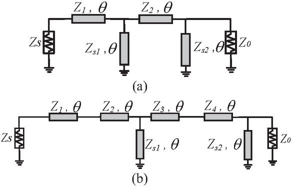
Figure 1 Topologies of proposed wideband filtering transformers with two short-circuited stubs: (a) three-pole impedance transformer and (b) four-pole impedance transformer.
2 DESIGN OF A WIDEBAND FILTERING IMPEDANCE TRANSFORMER
Figures 1 (a) and (b) show the two topologies of the proposed wideband filtering transformer with two shortcircuited stubs. They are three- and four-pole impedance transformers, respectively. To demonstrate the synthesis method, the detailed synthesis procedures of the filtering transformer in Fig. 1 (a) are summarized. The overall matrix of the filtering transformer is expressed as:
| (1) |
where and are the matrix of lines and and are the matrix of shunt shortcircuited stubs. Based on the synthesis theory in [28, 29, 30], the squared magnitude of the transmission coefficient with port impedances and can be derived:
| (2) |
It is assumed herein that the impedance transforming ratio of the proposed filtering transformer is . All impedance parameters are normalized by the load impedance . Thus, the characteristic impedance parameters can be achieved as , and . Equation (2) can be transformed as:
| (3) |
Here, the function can be derived as:
| (4) |
where:
| (5a) | ||
| (5b) | ||
| (5c) | ||
| (5d) |
The squared magnitude of transmission coefficient can also be mathematically expressed by Chebyshev polynomials as:
| (6) |
and
| (7a) | |
| (7b) |
Here is the specified equal-ripple constant in the passband and is the phase at lower cutoff frequency. Because of the frequency-distribution characteristic of transmission lines, the upper cutoff frequency of this bandpass filter appears at (). Based on the relationship among those variables in (7a) and (7b), the cosine function in (6) can be expanded as:
| (8) |
where and are the Chebyshev polynomial functions of the first and second kinds of degree . Using the identity for and :
| (9) |
The targeted transfer function in (3) can be analytically expressed in terms of the two kinds of Chebyshev functions. To make (3) have the same response as (6), and in equation (6) must be selected as 3 and 1, such that:
| (10) |
where:
| (11a) | ||
| (11b) |
In (10), is the equal-ripple constant in relevance to the specified within an operating band and is the quantity related to the specified FBW such that:
| (12a) | |
| (12b) | |
| (12c) |
By solving , and , the four normalized impedance parameters , and are all determined by the specified FBW, , and .
The detailed design procedure is described as follows.
• Determine all the characteristic impedances involved in ideal models of wideband transformer in Fig. 1 (a) with specified FBW and using the above-described synthesis method;
• Map the above-derived characteristic impedances and electrical length into their respective initial physical dimensions;
• Execute slight adjustment of the physical dimensions in order to compensate for some unexpected spurious effects in the microstrip-line structure, e.g., frequency dispersion, bend/step discontinuities, and so on.
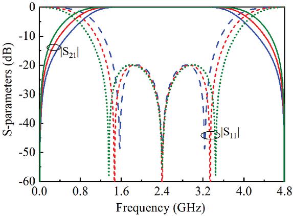
Figure 2 impedance transformers with and .
Table 1 Impedance parameters of filtering transformers with FBW of , and , impedance transformer ratio of 6.5, 6, 5.5, and 2.3, under condition of
| FBW | Impedance Parameters | ||||
| 6.5 | 52.2 | 133.2 | 33.7 | 45.4 | |
| 6 | 55.5 | 136.1 | 38.3 | 71.1 | |
| 5.5 | 59.3 | 139.2 | 44.1 | 133.7 | |
| 2.3 | 47.4 | 72.0 | 91.9 | 140.8 | |
To demonstrate the feasibility of the bandwidth, Fig. 2 presents the impedance transformers with FBW and of 20 dB. The simulated results show good agreement with the prescribed specifications, validating the synthesis theory. Table 1 presents the impedance parameters of the filtering transformers with FBW of 62%, 70%, 80%, and 106%, impedance transformer ratio of , and 2.3, under the condition of . All the impedance parameters are within the achievable range of microstrip technology.
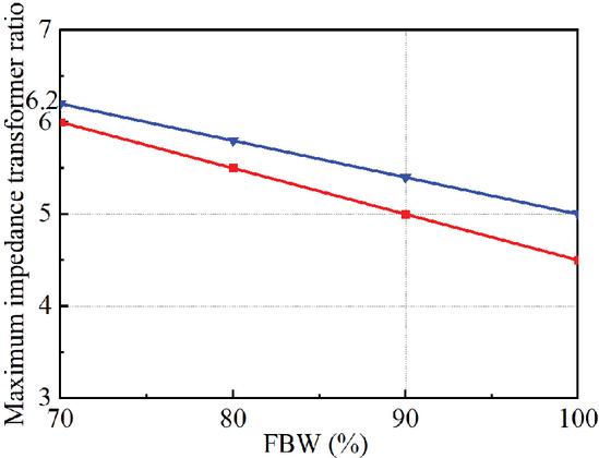
Figure 3 Maximum available impedance transformer ratio of proposed structure in Figs. 1 (a) and (b), under condition of of 15 dB.
Table 2 Impedance parameters of filtering transformers with FBW of 100%, transformer ratio of 2-5, under condition of
| FBW | Impedance Parameters | ||||||
| 2 | 100% | 56.5 | 21.1 | 18.9 | 35.9 | 8.5 | 132.5 |
| 3 | 100% | 84.7 | 31.6 | 26.3 | 40.8 | 13.2 | 91.8 |
| 4 | 100% | 113 | 42.1 | 33.1 | 44.4 | 18.2 | 77.6 |
| 5 | 100% | 141.3 | 52.7 | 39.4 | 47.3 | 23.3 | 70.1 |
By using the synthesis method, the structure in Fig. 1 (b) can also be synthesized following the similar design procedures in [31, 32]. Figure 3 presents the maximum available filtering impedance transformer ratio of the proposed structure in Figs. 1 (a) and (b), under the condition of . It can be observed that as the FBW increases, the maximum achievable impedance transformation ratio decreases. Regarding the structure in Fig. 1 (a), when the FBWs are selected as 70%, 80%, 90%, and 100%, the maximum achievable impedance transformation ratios are , and 4.5. Regarding structure in Fig. 1 (b), when the FBWs are selected as 70%, 80%, 90%, and 100%, the maximum achievable impedance transformation ratios are , and 5. Table 2 summarizes the impedance parameters of the filtering transformers with FBW of 100%, impedance transformer ratio of 2–5, under condition of . As the impedance ratio increases, the impedance , and increases while the impedance decreases. Generally, the available impedance is lower than , thus the maximum available impedance transformer ratio is 5 when the FBW is chosen as 100%.
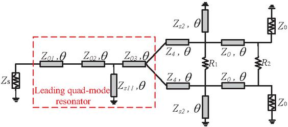
Figure 4 Proposed wideband filtering power divider with leading quad-mode resonator.
Figure 4 shows the schematic of the proposed wideband filtering power divider with leading quad-mode resonator. The leading part introduces four poles and jointly realizes five-pole Chebyshev response. The isolation response also has four approximate matching points. Attributing to the leading quad-mode resonator, wide operating bandwidth and isolation bandwidth are both achieved. As shown in Fig. 4, isolation resistors and are added between the two filtering branches. To demonstrate the function of the isolation resistor, theoretical results of the proposed wideband filtering transformer are designed and simulated. The wideband power divider with center frequency of 2.4 GHz, , and is simulated with one isolation resistor and two isolation resistors. The circuit parameters in Fig. 4 are , , , , , and . By trading off the matching property and isolation performance, the values of the isolation resistors can be selected. Figure 5 illustrates the theoretical results of the proposed wideband filtering transformer with one isolation resistor , under condition of bandwidth of and of 15 dB. The five-pole Chebyshev response has been well achieved. Unfortunately, the responses of are degraded. To solve the problem, an additional resistor is introduced as , good matching property of , and are realized, as shown in Fig. 6. The fully matching bandwidth and the isolation bandwidth are both 100%.
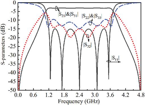
Figure 5 Theoretical results of proposed wideband filtering transformer with one isolation resistor , under condition of bandwidth of and of 15 dB.
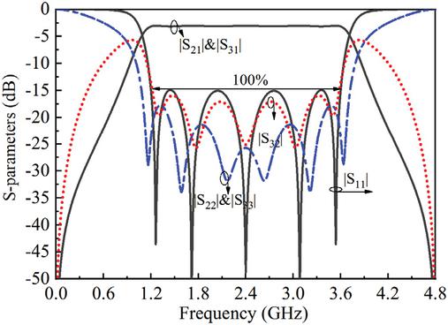
Figure 6 Theoretical results of proposed wideband filtering transformer with two isolation resistors and , under condition of bandwidth of and of 15 dB.
3 SIMULATION AND EXPERIMENT
For verification, a wideband impedance transformer with center frequency of , and is designed, simulated in ADS software, and fabricated on RO4003C substrate with relative permittivity of 3.55 and thickness of 0.508 mm. The impedance parameters are , and . As such, the strip widths and lengths of the two short-circuited microstrip-line stubs are determined as: , , and . The strip widths and lengths of the two microstrip-line sections in the middle are equal to: , and (unit: mm). The photograph of the fabricated wideband filtering impedance transformer is shown in Fig. 7. During measurement, the TRL calibration procedure is applied to calibrate out the effects of the SMA connectors and feeding microstrip lines. The scattering parameters are measured between the two ports and referenced to a source and a load impedance. As illustrated in Fig. 8, the measured center frequency, bandwidth, maximal , and minimal insertion loss are , and 0.3 dB, respectively. The bandwidth is from 1.2 to 3.62 GHz. The simulated and measured results show close agreement, validating the design’s effectiveness.
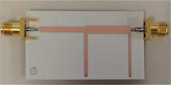
Figure 7 Photograph of filtering impedance transformer in Fig. 1 (a).
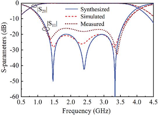
Figure 8 Simulated and measured results of designed filtering transformer circuit in Fig. 1 (a).
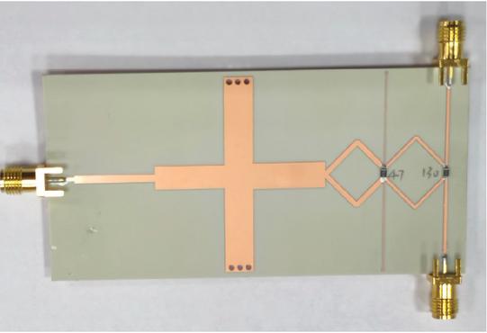
Figure 9 Photograph of wideband power divider in Fig. 4.
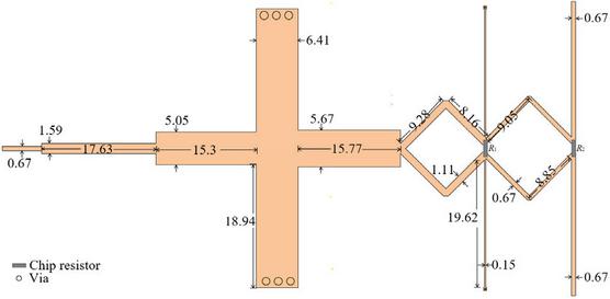
Figure 10 Dimensions of proposed power divider.
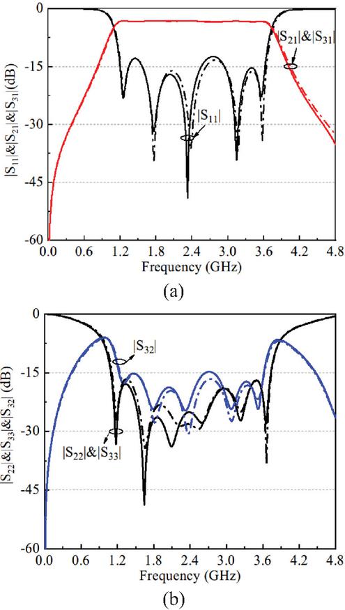
Figure 11 Simulated and measured S-parameters of proposed wideband filtering power divider: (a) magnitude response of , and and (b) magnitude response of , and .
To verify the proposed method, a wideband power divider shown in Fig. 4 with and is designed, simulated in ADS software, and fabricated on RO4003C substrate with relative permittivity of 3.55 and thickness of 0.305 mm. Figures 9 and 10 show the photograph and physical layout of the fabricated wideband power divider. Figure 11 presents the simulated and measured S-parameters of the proposed wideband filtering power divider. Figure 11 (a) shows the simulated and measured magnitude response of , and of the proposed wideband power divider. The simulated operating band range is 1.18–3.65 GHz with 12 dB input bandwidth of 102.2%, and the measured operating band is 1.18–3.66 GHz with 13 dB input bandwidth of 102.4%. The measured magnitude curve of and range from 3.34 dB to 3.16 dB across the bandwidth. In this frequency range, the measured in-band minimal is 13.3 dB and the simulated one is 12.4 dB, respectively. Figure 11 (b) presents the isolation performance and matching property and . Within the passband, the simulated and measured in-band isolation achieves better than 14.7 dB and 15.3 dB, respectively. The measured isolation bandwidth is better than 15 dB, and the simulated isolation bandwidth is better than 14 dB, both achieving 100%. Moreover, the simulated and measured magnitudes of and are with corresponding 15 dB bandwidths of 109.7%. The simulated and measured S-parameters of the designed power divider is in good agreement with the theoretical results shown in Fig. 6. The experimental results of the design example have validated the effectiveness of the design method.
Table 3 Comparison of proposed power divider and recently published works
| Ref. | Freq. | FBW | Filtering | Isolation |
| (GHz) | Implanted | Bandwidth | ||
| 25 | 3.54 | 17.3% | yes | 17.3% |
| 16 | 0.5 | 20% | no | 20% |
| 17 | 1 | 27% | no | 63% |
| 20 | 2 | 65% | no | 65% (15 dB) |
| 26 | 2.35 | 70% | yes | 70% |
| 27 | 1.8 | 73% | yes | 73% |
| 22 | 2.5 | 78% | yes | 78% |
| This Work | 2.4 | 102% | yes | 100% |
Table 3 tabulates the comparison of proposed power divider and recently published works. The classic Wilkinson power divider in [16] exhibits a limited bandwidth. The modified Wilkinson power divider in [17] enhances the isolation bandwidth, but its operational bandwidth remains constrained. The modified Gysel power divider in [20] achieves broader bandwidth. However, the references in [16, 17, 20] all lack integrated filtering functionality. In contrast to the filtering power divider reported in [25, 26, 27], the proposed design shows superior performance in both matching and isolation bandwidths. Furthermore, our work is guided by a systematic synthesis procedure that allows direct circuit derivation from stated specifications.
4 CONCLUSION
This paper has proposed two novel classes of wideband filtering impedance transformers with designable operating bandwidth and enhanced impedance transformation ratio, addressing the limitations of existing designs that lack systematic synthesis methods or suffer from narrow bandwidth. The proposed topologies generate multiple transmission poles within the passband, achieving wider bandwidth and enhanced impedance transformation ratios. The proposed synthesis method enables direct and systematic design of impedance transformers with specified bandwidth, , and transformation ratio, which significantly enhances design flexibility for practical RF front-end modules. To validate this approach, a wideband filtering transformer with 90% fractional bandwidth, impedance ratio of , and 20-dB is designed, simulated, and measured. In addition, a wideband power divider based on the proposed filtering transformer is implemented, demonstrating good filtering and isolation performance. Future research will extend the proposed synthesis method to develop tunable or reconfigurable impedance transformers for multiband matching, and to integrate them into multifunctional circuits such as balanced-to-unbalanced filtering networks or Doherty power amplifiers, where wideband impedance transformation is required.
ACKNOWLEDGMENT
This work was supported in part by the Zhejiang Provincial Natural Science Foundation of China under Grant LQN26F010015.
REFERENCES
[1] S. Chen, G. Zhao, M. Tang, and Y. Yu, “Wideband filtering impedance transformer based on transversal interaction concept,” Electron. Lett., vol. 54, no. 6, pp. 368–370, Oct. 2018.
[2] P. Kim, G. Chaudhary, and Y. Jeong, “Wideband impedance transformer with out-of-band suppression characteristics,” Microw. Opt. Technol. Lett., vol. 56, no. 11, pp. 2612–2616, June 2014.
[3] X. Wang, Z. Ma, T. Xie, M. Ohira, C.-P. Chen, and G. Lu, “Synthesis theory of ultra-wideband bandpass transformer and its Wilkinson power divider application with perfect in-band reflection/isolation,” IEEE Trans. Microw. Theory Techn., vol. 67, no. 8, pp. 3377–3390, Aug. 2019.
[4] M. Chongcheawchamnan, S. Patisang, S. Srisathit, R. Phromloungsri, and S. Bunnjaweht, “Analysis and design of a three-section transmission-line transformer,” IEEE Trans. Microw. Theory Techn., vol. 53, no. 7, pp. 2458–2462, July 2005.
[5] R. Darraji, M. M. Honari, R. Mirzavand, F. M. Ghannouchi, and P. Mouavi, “Wideband two-section impedance transformer with flat real-to-real impedance matching,” IEEE Microw. Wireless Compon. Lett., vol. 26, no. 5, pp. 313–315, May 2016.
[6] Q. Wu and L. Zhu, “Wideband impedance transformers on parallel-coupled and multisection microstrip lines: Synthesis design and implementation,” IEEE Trans. Compon. Packag. Manuf. Technol., vol. 6, no. 12, pp. 1873–1880, Dec. 2016.
[7] Q. Wu and L. Zhu, “Wideband impedance transformers with good frequency selectivity based on multisection quarter-wave lines and short-circuited stubs,” IEEE Microw. Wireless Compon. Lett., vol. 26, no. 5, pp. 337–339, May 2016.
[8] Q. Wu and L. Zhu, “Synthesis design of a wideband impedance transformer consisting of two-section coupled lines,” IET Microw. Antennas Propag., vol. 11, no. 1, pp. 144–150, July 2017.
[9] P. Kim, G. Chaudhary, and Y. Jeong, “Ultra-high transforming ratio coupled line impedance transformer with bandpass response,” IEEE Microw. Wireless Compon. Lett., vol. 25, no. 7, pp. 445–447, July 2017.
[10] C. W. Hsieh, S. C. Lin, and J. Y. Li, “Bandpass impedance transformers with extremely high transforming ratios using -tapped feeds,” IEEE Access, vol. 6, pp. 28193–28202, June 2018.
[11] Z. Zhuang, Y. Wu, M. Kong, and W. Wang, “High-selectivity single-ended/balanced DC-block filtering impedance transformer and its application on power amplifier,” IEEE Trans. Circuits Syst. I, Reg. Papers, vol. 67, no. 12, pp. 4360–4369, Dec. 2017.
[12] F. Liu, K. Fan, X. Zhang, Q. Tan, X. Zhang, and L. Liu, “A millimeter-wave wideband low-sidelobe slotted antenna array based on a high power divider ratio microstrip ridge gap waveguide feed network,” IEEE Antennas Wireless Propag. Lett., vol. 24, no. 12, pp. 4780–4784, Dec. 2025.
[13] S. Y. Zheng, Z. W. Liu, Y. M. Pan, Y. Wu, W. S. Chan, and Y. Liu, “Bandpass filtering Doherty power amplifier with enhanced efficiency and wideband harmonic suppression,” IEEE Trans. Circuits Syst. I, Reg. Papers, vol. 63, no. 3, pp. 337–346, Mar. 2016.
[14] O. Kasar, M. Kahriman, and M. A. Gozel, “Application of ultra wideband RF energy harvesting by using multisection Wilkinson power combiner,” Int. J. RF Microw. Comput.-Aided Eng., vol. 29, no. 1, pp. 1–8, 2019.
[15] D. M. Pozar, Microwave Engineering, 3rd ed. New York: Wiley, 2005.
[16] E. Wilkinson, “An N-way hybrid power divider,” IEEE Trans. Microw. Theory Tech., vol. 8, no. 1, pp. 116–118, Jan. 1960.
[17] R. Mirzavand, M. M. Honari, A. Abdipour, and G. Mordi, “Compact microstrip Wilkinson power dividers with harmonic suppression and arbitrary power division ratios,” IEEE Trans. Microw. Theory Techn., vol. 61, no. 1, pp. 61–68, Jan. 2013.
[18] C. Bao, X. Wang, Z. Ma, C.-P. Chen, and G. Lu, “An optimization algorithm in ultrawideband bandpass Wilkinson power divider for controllable equal-ripple level,” IEEE Microw. Wireless Compon. Lett., vol. 30, no. 9, pp. 861–864, Sep. 2020.
[19] S. Kouhpayeh-Zadeh-Esfahani, K. Afrooz, and E. Moradi, “A 10:1 unequal Gysel power divider/ combiner,” Microw. Opt. Technol. Lett., vol. 58, no. 11, pp. 2689–2692, Aug. 2016.
[20] X. Wang, K.-L. Wu, and W.-Y. Yin, “A compact Gysel power divider with unequal power-dividing ratio using one resistor,” IEEE Trans. Microw. Theory Techn., vol. 62, no. 7, pp. 1480–1486, July 2014.
[21] H. Chen, Y. Zhou, T. Zhang, W. Che, and Q. Xue, “N-way Gysel power divider with arbitrary power-dividing ratio,” IEEE Trans. Microw. Theory Techn., vol. 67, no. 2, pp. 659–669, Feb. 2019.
[22] Y. Liu, L. Zhu, and S. Sun, “Proposal and design of a power divider with wideband power division and port-to-port isolation: A new topology,” IEEE Trans. Microw. Theory Techn., vol. 68, no. 4, pp. 1431–1438, Dec. 2019.
[23] B.-G. Liu, J.-C. Pu, H. Tang, Y. Cheng, and C.-H. Cheng, “Compact quadruple-mode FSIW filtering power divider with high isolation using embedded capacitive isolation network,” IEEE Trans. Circuits Syst. II, Exp. Briefs, vol. 71, no. 8, pp. 3750–3754, Aug. 2024.
[24] L. Jiao, Y. Wu, Y. Liu, Q. Xue, and Z. Ghassemlooy, “Wideband filtering power divider with embedded transversal signal-interference sections,” IEEE Microw. Wireless Compon. Lett., vol. 27, no. 12, pp. 1068–1070, Dec. 2017.
[25] D. Li, L. Zhang, J. Wang, Y. Liu, and Q. Chen, “Characteristic analysis of parallel and anti-parallel coupled line structures and their integrated design in filtering power dividers,” IEEE Trans. Compon. Packag. Manuf. Technol., vol. 13, no. 11, pp. 1845–1856, Nov. 2023.
[26] L. Liu, L. Zhu, Z.-B. Wang, and Y.-R. Zhang, “Proposal and synthesis of self-packaged wideband bandpass power divider with constant power ratio and full phase difference range,” IEEE Trans. Microw. Theory Tech., vol. 73, no. 3, pp. 1646–1658, Mar. 2025.
[27] Y. Zhang, H. Liu, S. Chen, Z. Wang, and S. Fang, “All-port-reflectionless wideband filtering power divider using five-line coupled structure,” IEEE Microw. Wireless Technol. Lett., vol. 35, no. 1, pp. 31–34, Jan. 2025.
[28] R. Levy and L. F. Lind, “Synthesis of symmetrical branch-guide directional couplers,” IEEE Trans. Microw. Theory Tech., vol. 16, no. 2, pp. 80–89, Feb. 1968.
[29] M. C. Horton and R. J. Wenzel, “General theory and design of optimum quarter-wave TEM filters,” IEEE Trans. Microw. Theory Tech., vol. 13, no. 3, pp. 316–327, Jan. 1965.
[30] H. J. Carlin and W. Kohler, “Direct synthesis of band-pass transmission line structures,” IEEE Trans. Microw. Theory Tech., vol. 13, no. 5, pp. 283–297, Dec. 1965.
[31] L. Zhu, S. Sun, and R. Li, Microwave Bandpass Filters for Wideband Communications. New York, NY: Wiley, 2012.
[32] P. Chen, X. Wang, L. Zhu, and G. Lu, “Design of wideband bandpass filters based on three types of coupled stub-loaded resonators,” IEEE Trans. Microw. Theory Tech., vol. 73, no. 12, pp. 10617–10631, Dec. 2025.
BIOGRAPHIES

Haili Zhang received the B.S. degree from Henan University, China, in 2003 and the M.S. degree in material engineering from university of electronic science and technology of China, in 2008. From 2006 to 2009, he was a quality engineer with the Chinese People’s Liberation Army 3303 Factory. He has worked in three companies as R&D manager: Dongguan ACE Technology Co. Ltd., Guangdong Shenglu Telecommunication Technology Co. Ltd., and Shenzhen Dafu Telecommunication Technology Co. Ltd. In 2010, he joined Zhejiang Fashion Institute of Technology and founded the faculty of urban railway communication, engaging in management, teaching, and researching. He is currently studying for a Ph.D. degree at the Faculty of Electrical Engineering and Computer Science, Ningbo University. His research interests include RF modules, smart antenna, and radar.

Zhenzhong Chen received the Ph.D. degree in electromagnetic field and microwave technology from Nanjing University of Science and Technology, Nanjing, China, in 2023. He is currently a Lecturer with Ningbo University, Ningbo. He serves as an Active Reviewer for multiple academic journals. His research interests include array antenna, filtering antenna, phased-array antennas, and microwave/millimeter-wave circuit integration.

Taijun Liu (Senior Member, IEEE) received the B.S. degree in applied physics from the China University of Petroleum, Dongying, China, in 1986, the M.Eng. in electrical engineering from the University of Electronic Science and Technology of China, Chengdu, in 1989, and he received the Ph.D. degree at the École Poly technique de Montréal, Université de Montréal, Montréal, QC, Canada, in 2005. He is currently working with Faculty of Electrical Engineering and Computer Science, Ningbo University, as a professor. His current research interests are nonlinear modeling and linearization of wide-band transmitters/power amplifiers, and design of ultra linear highefficiency intelligent power amplifiers for broad-band wireless and satellite communications system.
ACES JOURNAL, Vol. 41, No. 4, 367–375
DOI: 10.13052/2026.ACES.J.410409
© 2025 River Publishers