Comparative Analysis of a Novel Linear Rotary Switch Reluctance Machine
Hao Chen1, 2, 3, 4, Cheng Liu1, Marcin Wardach5, Javokhir Toshov6, Xing Wang2, 3, 4, Ali Asghar Memon7, Bodrenkov Evgenii Alexandrovich8, Nikolay Korovkin8, Sakhno Liudmila8, Emmanuel Karapidakis9, Aris Dimeas10, Sherif Moussa11, and Habes Ali Khawaldeh12
1School of Electrical Engineering China University of Mining and Technology, Xuzhou 221116, China
hchen@cumt.edu.cn, Chengliu97@cumt.edu.cn
2Shenzhen Research Institute China University of Mining and Technology, Shenzhen 515100, China
3512@cumt.edu.cn
3Jiangsu Province Foreign Expert Workshop on New Energy Power Generation and Electric Transportation Xuzhou 221008, China
4International Joint Research Center of Central and Eastern European Countries on New Energy Electric Vehicle Technology and Equipment Xuzhou 221008, China
5Department of Electrical Machines and Drives West Pomeranian University of Technology, Sikorskiego 37, 70-313 Szczecin, Poland
6Tashkent State Technical University University Street No. 2, 100095 Tashkent, Uzbekistan
7Mehran University of Engineering and Technology Department of Electrical Engineering, Jamshoro, Pakistan
8The Institute of Energy Peter the Great Saint Petersburg Polytechnic University, Saint Petersburg, Russia
9School of Engineering Hellenic Mediterranean University, Estavromenos Campus, 71004 Heraklio, Crete, Greece
10Athens National University of Technology Greece
11School of Engineering Canadian University Dubai, 117781, Sheikh Zayed Road, Dubai, United Arab Emirates
12The Renewable Energy Engineering Department Faculty of Engineering, Al al-Bayt University, Mafraq, Jordan
∗Corresponding author
Submitted On: January 15, 2026
Accepted On: June 15, 2026
ABSTRACT
This paper proposes a novel tubular linear rotary switch reluctance machine (TLRSRM) with modular stator and rotor designs and studies its electromagnetic characteristics. Firstly, the topology and operating mechanism of the two-degree-of-freedom machine are presented. based on the proposed motor design process, the structural dimensions are initially determined, and the 3D finite element model (FEM) with its flux density distribution is provided. Secondly, a sensitivity analysis of critical structural parameters is conducted by using a parameter sweep method to investigate their influence on torque performance. Finally, to evaluate the motor’s static characteristics – including flux linkage, inductance, and torque/thrust – comparison analysis is performed between two TLRSRM variants featuring different winding configurations. Simulation results validate the feasibility of the proposed topology.
Keywords: 3D finite element model, magnetic field distribution, static electromagnetic characteristics, switched reluctance machine..
1 INTRODUCTION
Against the backdrop of deepening industrial intelligence and rapid development of integrated marine energy systems – such as combined offshore wind and wave power generation – diverse application scenarios demand higher levels of integration and multidimensional motion control capabilities from drive equipment. Traditional single-degree-of-freedom motors increasingly reveal limitations such as restricted functionality, complex system structures, and wasteful space utilization, making them ill-suited for efficient drive demands under complex operating conditions. Against this backdrop, multi-degree-of-freedom motor technology has emerged as a frontier research direction in the field of electric motors, owing to its integrated compact structure, highly consolidated functionality, and flexible motion control methods. Particularly, the switched reluctance motor (SRM) demonstrates broad application prospects in multi-degree-of-freedom drive systems due to its advantages of simple structure, solid robustness, and outstanding adaptability to harsh environments [1, 2, 3, 4].
As a novel motor with potential market applications, the dual-degree-of-freedom linear-rotary SRM enables simultaneous coordinated control of rotational and linear motion within a single unit. This capability unlocks significant engineering potential in systems requiring compound motion, such as high-end intelligent manufacturing and marine power generation installations. Currently, academic research and engineering practice remain largely focused on enhancing the performance of traditional single-degree-of-freedom reluctance motors. Research on dual-degree-of-freedom linear-rotary reluctance motors is still in its preliminary exploratory phase. The theoretical and methodological frameworks for aspects such as topological configuration design and electromagnetic coupling mechanism analysis require further establishment and refinement [5, 6, 7].
References [8, 9, 10] proposed a structurally simple rotary linear switched reluctance motor (RLSRM). The motor can generate motion in two degrees of freedom: the same shaft can undergo both linear rotation and displacement. It can be used in various advanced automotive applications where available space is limited. Reference [11] introduced a novel structure for a RLSRM. It is primarily designed for engaging and disengaging rotary gears. The motor comprises a three-phase 6/4 rotary SRM and a two-phase transverse flux linear SRM. Experimental validation confirms the constructed motor’s performance and applicability. Reference [12] proposes a novel direct-drive RLSRM. This motor offers advantages including robust mechanical structure, low manufacturing cost, and capability to operate in harsh environments. Reference [13] presents a linear SRM configuration for wave energy converters (WECs) with a segmented core structure, aiming to achieve higher force and efficiency. Reference [14] discusses an axial flux permanent magnet synchronous generator for buoy-type WECs. To enhance the performance of underwater WEC generators, [15] proposes a linear rotating axial flux modulator generator. To enable efficient, low-cost utilization of offshore renewable energy, [16] proposes a permanent magnet linear-rotary generator (LRG) system with a novel topology for direct-drive wave-wind hybrid energy conversion. The optimization process encompasses initial design, sensitivity analysis of optimization parameters, determination of weight factor for optimization objectives, and final decisionmaking. Results demonstrate that the proposed design and optimization effectively enhance the performance of the LRG.
The aforementioned literature has contributed various types of SRM structures, with corresponding electromagnetic simulations and experimental studies consistently validating the feasibility and effectiveness of these designs in achieving specific motion functions. Despite the clear performance advantages of these multi-degree-of-freedom structures, dual-degree-of-freedom motors capable of simultaneously outputting rotational and linear motion face inherent structural disadvantages compared to traditional single-degree-offreedom motors. The complexity of their motion mechanisms often introduces structural redundancy, leading to higher iron core material consumption and resulting in larger overall weight and volume for the motor’s effective moving parts. To leverage the power density enhancement advantages of modularization, this paper innovatively proposes a novel modular linear-rotary switched reluctance machine based on the research foundation of [17].
Compared to conventional integrated cores, adopting a modular stator and rotor topology presents several distinct physical and electromagnetic advantages crucial for multidimensional drive systems. First, the segmented design eliminates redundant iron core materials, thereby substantially reducing the inertial mass of the moving components and enhancing the dynamic response speed. Second, the discrete spatial arrangement of the modules creates an open physical structure, which significantly minimizes air resistance and windage losses during high-speed operations. Ultimately, these structural benefits synergistically reduce the overall motor weight and optimize the spatial magnetic circuit layout, culminating in a remarkable improvement in both torque density and power density. Its segmented stator-rotor structure significantly reduces motor weight, thereby improving power density. In summary, the lightweight, high-power-density motor solution proposed herein holds promise for industrial applications requiring composite motion, offering dual competitive advantages in both economic cost and overall performance.
Specifically, the research presented in this paper focuses on the conceptual design and theoretical modeling of the novel modular tubular linear rotary switch reluctance machine (TLRSRM) topology. The scope of the current work is limited to the systematic verification of the electromagnetic principles and modeling accuracy through 3D finite element analysis.
2 STRUCTURE AND OPERATING PRINCIPLE OF TLRSRM
The 3D structural model of the proposed TLRSRM is shown in Fig. 1. It can be seen that the proposed TLRSRM consists of segmented stator and rotor components. Its core structural feature lies in the configuration where 12 U-shaped stator modules and eight U-shaped rotor modules, uniformly distributed along the circumference, collectively form the motor’s magnetic circuit and moving assembly. Each U-shaped stator module is equipped with a bipolar winding set, where the two coils wound on the same module possess an identical number of turns but are wound in opposite directions to establish contrary magnetic polarities. A key aspect of the winding configuration is that coils from four stator modules, which are spatially separated by 90 degrees mechanically, are connected in series to constitute one phase winding. This specific interconnection pattern is repeated to form a complete and symmetrical three-phase armature winding system, which is essential for generating the requisite rotating or travelling magnetic fields for dual-degree-of-freedom operation. The motor’s magnetic circuit core (stator and rotor excitation sections) is laminated from 50DW470 silicon steel sheets to optimize magnetic permeability and control core losses. Collectively, this segmented and modular construction bestows several critical advantages. It substantially reduces the inertial mass of the moving components (primarily the rotor), which is pivotal for improving dynamic response. Furthermore, the open and segmented nature of the structure significantly diminishes air resistance or windage losses during high-speed rotation. These inherent benefits – weight reduction, lower windage loss, and optimized magnetic circuit – synergistically provide the foundational support necessary for achieving superior torque and power density outputs, which are paramount performance metrics for advanced motion control applications.
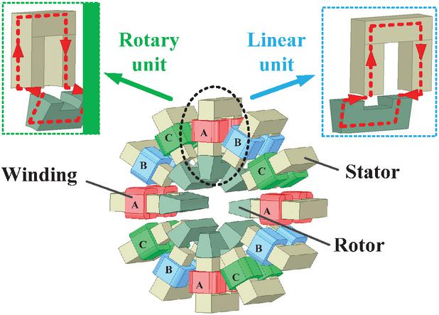
Figure 1 3D view of proposed TLRSRM model.
Additionally, as shown in Fig. 1, when the armature winding is energized, a distinct magnetic flux path is established within the motor. This path originates at one end of the energized U-shaped stator pole tooth. After traversing the stator pole tooth, the magnetic flux crosses the air gap radially and enters the corresponding rotor salient pole. Subsequently, the magnetic flux flows along the circumferential closed path of the U-shaped rotor core, reaching the rotor salient pole on the opposite side. It then again traverses the air gap radially, entering the adjacent stator pole. Finally, the magnetic flux forms a closed circuit through the stator back yoke, returning to the initial stator pole.
This magnetic circuit topology forms the core physical foundation for achieving dual-degree-of-freedom motion. To further clarify the dual-degree-of-freedom operating mechanism, the motion of the proposed TLRSRM is determined by the specific excitation patterns applied to the three-phase windings. For rotational motion, the phases are energized sequentially (e.g., A, B, C), generating an asymmetrical magnetic pull force circumferentially that acts on the salient poles to produce torque. Conversely, for pure linear motion, all three phases are excited simultaneously. Under this condition, the symmetrical radial forces cancel each other out entirely. The predominant axial magnetic flux then interacts with the rotor modules, generating purely axial electromagnetic forces that drive the components linearly. A summary of these phase excitation patterns is presented in Table 1.
This modular magnetic circuit and structural design offers significant advantages. First, it optimizes the magnetic path, substantially shortening the effective travel of the main magnetic flux and reducing the total magnetic resistance of the circuit.
Table 1 Phase excitation patterns for different motion types
| Motion | Excitation | Phase | Primary |
| Type | Strategy | Excitation | Force |
| Pattern | Generated | ||
| (Example) | |||
| Rotational Motion (Forward) | Sequential | A-B-C | Circumferential Torque |
| Rotational Motion (Reverse) | Sequential | A-C-B | Circumferential Torque |
| Linear Motion | Simultaneous | A, B, C | Axial Thrust |
| Coupled (Spiral) Motion | Sequential (while axially offset) | A-B-C | Torque + Axial Thrust |
Second, the compact magnetic circuit design allows for the arrangement of more efficient magnetic materials within the same volume, achieving miniaturization and weight reduction. The direct benefits include reduced hysteresis and eddy current losses in the core material and enhanced energy conversion efficiency, ultimately manifested as a comprehensive improvement in both torque density and power density of the motor.
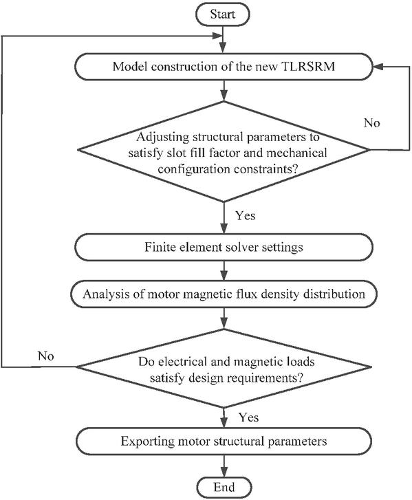
Figure 2 Design flowchart for the new TLRSRM structure.
The initial design flowchart for the novel TLRSRM structure described in this paper is shown in Fig. 2, where the current density is no greater than 6 A/mm2, and the slot fill factor is below 50%. Based on conventional design experience and the parameter selection criteria in Fig. 2, the initial dimensional parameters for the TLRSRM are selected and listed in Table 2.
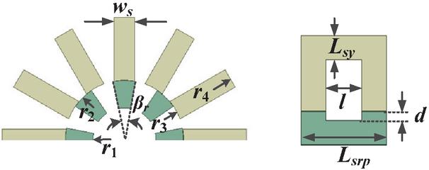
Figure 3 Structural dimension drawing.
The main structural parameters of the DSSRM are illustrated in Fig. 3.
Table 2 Structure parameters of the TLRSRM
| Parameter | Unit | Value |
| Stator outer diameter/ | mm | 310 |
| Stator inner diameter/ | mm | 150.8 |
| Rotor outer diameter/ | mm | 150 |
| Rotor inner diameter/ | mm | 80 |
| Rotor pole arc/ | deg | 9 |
| Stator pole width/ | mm | 25 |
| Stator yoke thickness/ | mm | 25 |
| Stator/Rotor axial length/ | mm | 90 |
| Stator/Rotor slot length/l | mm | 38 |
| Rotor slot depth/ | mm | 10 |
| Air gap length | mm | 0.5 |
| Number of turns per phase | / | 160 |
To preliminarily validate the magnetic pathway and operational principles of the TLRSRM, based on the design parameters provided in Table 1, this study constructed a finite element analysis model of the TLRSRM within the ANSYS simulation environment and conducted a systematic evaluation of its electromagnetic performance. The mesh partitioning of the minimal repeating unit structure of TLRSRM is shown in Fig. 4 (a), and the B-H curve for the silicon steel material used is shown in Fig. 4 (b). Figure 5 provides a comprehensive view of the finite element model (FEM) of this motor and its magnetic field distribution characteristics during a static parameter scan with a constant current applied, specifically when a 15 A excitation current is applied to the stator winding of Phase A. Figures 5 (a) and (b) show magnetic flux density contour plots for rotational and linear motion at the misaligned position. Figure 5 (c) shows magnetic flux density contour plots for both types of motion at the aligned position. The simulations are conducted in ANSYS Maxwell 3D software using the Magnetostatic solver to evaluate the static electromagnetic characteristics. To balance computational accuracy and speed, the gap size in the air gap is set to 1 mm, while the size of the core section is set to 10 mm.
Observation of the contour distributions indicates relatively uniform magnetic flux density across the tooth and yoke regions of both stator and rotor cores, with no significant localized saturation observed. Notably, peak flux density areas are concentrated at the pole tips near the air gap, consistent with the physical principles governing magnetic field distribution. Simulation data indicates that, throughout the entire operating cycle, the maximum magnetic flux density in the core material remains consistently below 1.8 tesla. This result not only demonstrates the full utilization of the magnetic material but also validates the rationality and feasibility of the proposed motor structure from an electromagnetic design perspective.
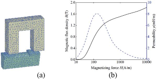
Figure 4 Finite element mesh diagram: (a) grid division and (b) material B-H curve.

Figure 5 FE model and magnetic field distribution of TLRSRM: (a) unaligned position in rotary motion, (b) unaligned position in linear motion, and (c) aligned position in rotary/linear motion.
3 SENSITIVITY ANALYSIS OF TLRSRM
In rotary and linear motion, electromagnetic torque and electromagnetic thrust are among the core performance metrics. Here, we present the theoretical formula using rotary motion as an example. Based on the static torque obtained at different angles through the finite element method, the average static torque of the motor can be derived from the following equation:
| (1) |
where denotes the rotor pole pitch in radians and is the electromagnetic torque. Average static torque is a key indicator for evaluating a motor’s static torque output capability.
Considering that the proposed TLRSRM structure must simultaneously satisfy requirements for high average torque and low torque ripple, two objectives average static torque and static torque smoothness coefficient – are selected as optimization targets. Three parameters – rotor pole arc angle , stator/rotor slot length , and rotor slot depth – are chosen as design variables for the optimized design of the TLRSRM. During sensitivity analysis of each structural parameter, the values of the remaining parameters under analysis remain constant, and the motor operates under rated conditions. Single-parameter sensitivity analysis for this section is shown in Fig. 6.
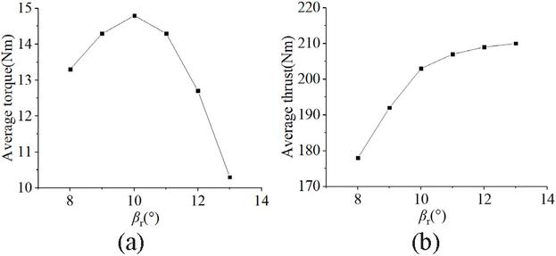
Figure 6 Sensitivity analysis results under different rotor pole arc : (a) rotary motion and (b) linear motion.
As shown in Fig. 6, the relationship curve between the average torque/thrust of the MLRSRM and the rotor pole arc angle indicates that, in the rotational motion mode, the mean electromagnetic torque exhibits a non-monotonic variation pattern – first increasing and then decreasing – as the angle decreases, reaching its peak at of . For the linear motion mode, the average electromagnetic thrust exhibits a continuously increasing trend with increasing . Beyond a certain critical value, the rate of increase gradually converges. Considering all factors, is ultimately determined as the optimal design parameter for the rotor pole arc.
As shown in Fig. 7, the relationship curve between the average torque/thrust of the MLRSRM and the stator/rotor slot length indicates that, in rotational motion mode, as increases, the average electromagnetic torque exhibits a decreasing trend, while the average electromagnetic thrust shows an increasing trend. After comprehensive consideration of all factors, 38 mm is ultimately determined as the optimal design parameter for the stator/rotor slot length.
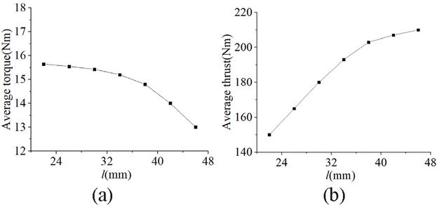
Figure 7 Sensitivity analysis results under different stator/rotor slot length : (a) rotary motion and (b) linear motion.
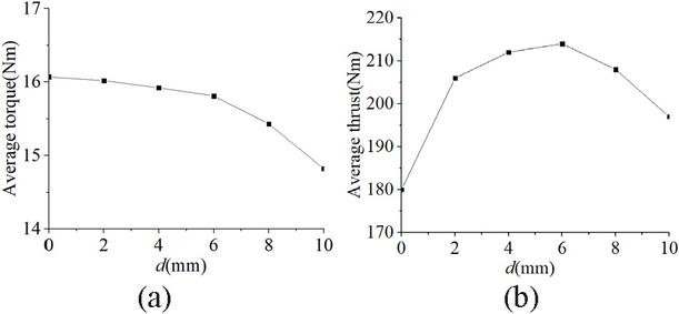
Figure 8 Sensitivity analysis results under different rotor slot depth : (a) rotary motion and (b) linear motion.
It can be seen from Fig. 8 that the relationship curve between the average torque/thrust of the MLRSRM and the stator/rotor slot depth indicates: in the rotational motion mode, as increases, the average electromagnetic torque shows a decreasing trend, while the average electromagnetic thrust first increases and then decreases. After comprehensively considering all factors, 5 mm was ultimately determined as the optimal design parameter for the stator/rotor slot depth.
It should be emphasized that identifying the final structural parameters entails a critical compromise between the rotary and linear motion capabilities. Because parameters optimal for the rotational torque frequently conflict with those optimal for the linear thrust, optimizing a single metric inevitably leads to the severe degradation of the other. Consequently, the final parameter selection adopts a balanced optimization strategy aimed at maximizing the overall dual degree of freedom performance. Specifically, the chosen values represent the optimal intersection points where the rotary torque is maintained near its peak value while the linear thrust reaches a stable high-performance plateau. This balancing philosophy ensures that the proposed motor delivers robust and symmetrical multidimensional driving forces under complex operational conditions.
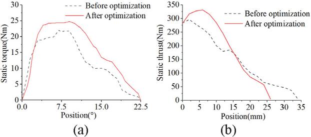
Figure 9 Performance comparison before and after optimization: (a) static torque waveform and (b) static thrust waveform.
Based on the sensitivity analysis of the aforementioned key design parameters, Fig. 9 illustrates the comparison of the electromagnetic performance of the TLRSRM before and after parameter optimization. This is specifically demonstrated through the static torque and static thrust characteristic curves at different rotor positions. Analysis of the data in Fig. 9 reveals that the optimized motor exhibits significantly enhanced performance: its peak static torque increased by 21.6% compared to the original design, while the peak static thrust improved by 36.6%.
4 PERFORMANCE COMPARISON OF DIFFERENT TLRSRM STRUCTURES
To fully evaluate the electromagnetic performance of the proposed TLRSRM structure, this section conducts a comparative analysis of two TLRSRM designs with distinct winding configurations. The 3D models of both structures are shown in Fig. 10, namely the baseline T-I type (originally presented in Fig. 1) and the proposed T-II type. In the T-I type, the winding coils are wound on adjacent teeth of the U-shaped stator, while in the T-II type, the winding coils are wound on the stator yoke. For a fair comparison, both structures have the same number of winding-turns per phase, as well as identical motor volume and rated conditions.
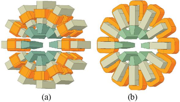
Figure 10 Comparison of TLRSRM 3D models: (a) T-I type and (b) T-II type.
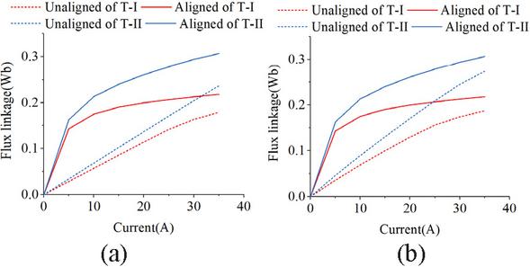
Figure 11 Flux linkage curve: (a) rotary motion and (b) linear motion.
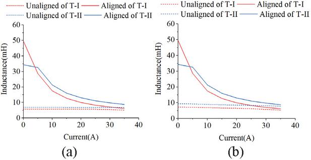
Figure 12 Inductance curve: (a) rotary motion and (b) linear motion.
The core electromagnetic characteristics of SRMs are primarily reflected in key parameters such as magnetic flux linkage, inductance, and output torque. Figures 11 and 12 illustrate the variation patterns of magnetic flux linkage and inductance with current for a single stator pole in non-aligned and aligned positions under rotational and linear motion modes for two contrasting structures.
During the low-current excitation phase, magnetic flux in both positions increases approximately linearly with excitation current, while corresponding inductance values remain largely constant. This indicates the motor magnetic circuit operates within the linear region of the core material’s magnetization curve. However, once the current exceeds a specific saturation threshold, the magnetic flux growth rate at the aligned position noticeably slows, exhibiting nonlinear saturation characteristics, while its inductance value simultaneously decreases significantly. In stark contrast, the magnetic flux and inductance characteristics at the non-aligned position show no significant changes across the entire current range, consistently maintaining a good linear relationship.
The fundamental cause of this difference lies in the varying magnetic resistance within the circuit. At the aligned position, magnetic flux concentrates through the stator and rotor poles, forming a low-resistance path that rapidly increases local magnetic flux density in the core. When current increases to saturate the silicon steel laminations (typically within the 1.8–2.0 T range), the material’s permeability decreases and magnetic resistance increases, triggering nonlinear changes in magnetic flux linkage and inductance. In the nonaligned position, however, the air gap magnetic resistance remains dominant, resulting in a lower magnetic flux density level in the core. Consequently, it is difficult for the core to reach saturation.
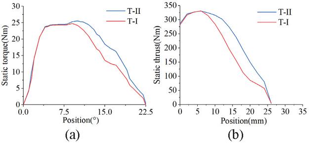
Figure 13 Static torque/thrust curve: (a) rotary motion and (b) linear motion.
Figure 12 shows the static torque/thrust variation waveforms for the T-I and T-II structural types at a rated current of 15 A. The static torque and thrust for TI are 15.8 Nm and 213 Nm, respectively; T-II exhibits higher static torque and thrust values of 17.6 Nm and 240 Nm. The data indicates that T-II exhibits an 11.52% increase in static torque and a 12.68% increase in static thrust, compared to T-I. These results demonstrate that the structure with windings wrapped around the stator yoke exhibits superior electromagnetic performance compared to the structure with windings wrapped around the stator pole positions. The ripple percentage () is defined and calculated as follows:
| (2) |
where , and represent the maximum, minimum, and average values of the electromagnetic torque (or thrust) over the effective conduction interval.
To address the critical aspect of motion stability, this section further evaluates the static smoothness coefficient for both structural types. Because the proposed analysis focuses on static characteristics, the static torque ripple of the output torque and thrust over the effective conduction zone is adopted as the smoothness metric. Analyzing the flat-top region spanning from to for the rotary mode, the T-II configuration yields a smaller static torque ripple of 42.2% compared to the 64.0% of the T-I configuration. Similarly, within the linear conduction interval from 3 mm to 17.5 mm, the extended high thrust plateau of the T-II structure results in a reduced static thrust ripple of 54.5% contrasting with the 85.7% of the T-I design. The data indicates that winding the coils around the stator yoke effectively diminishes output fluctuations, thereby providing superior motion smoothness for complex multidimensional drive applications.
5 CONCLUSION
This paper proposes a novel TLRSRM employing a modular stator-rotor design. Its electromagnetic characteristics and structural parameter sensitivity were systematically investigated through three-dimensional finite element analysis. Simulation results demonstrate that this topology effectively achieves dual-degree-offreedom rotational and linear motion, with a rational magnetic field distribution and core magnetic flux density consistently maintained within safe limits. Parameter sensitivity analysis identified optimal solutions for critical dimensions such as rotor pole arcs. Post-optimization, static torque and thrust increased by 21.6% and 36.6%, respectively. Further comparison of two winding configurations (T-I and T-II) revealed that the T-II structure with yoke windings outperformed the T-I type with pole windings in both static torque and thrust, achieving improvements of 11.52% and 12.68%, respectively. The proposed TLRSRM structure demonstrates significant advantages in integration, power density, and output performance, offering a viable new solution for high-performance multi-degree-of-freedom drive systems.
ACKNOWLEDGMENT
This work is supported by the National Natural Science Foundation of China International (regional) cooperation and exchange projects NSFC-RSF under Grant W2412064 and the Shenzhen Collaborative Innovation Special Plan International Cooperation Research Project under Grant GJHZ20240218114300002.
REFERENCES
[1] H. Chen, R. Nie, and X. Li, “A transverse-flux single-phase tubular switched reluctance linear machine with 4 poles,” IEEE Transactions on Applied Superconductivity, vol. 31, no. 8, pp. 1–4, Nov. 2021.
[2] K. Manohar and K. Srichandan, “Analysis of quadrupole magnetic field reluctance-based launcher with different coil switching patterns,” IEEE Transactions on Plasma Science, vol. 51, no. 5, pp. 1370–1376, May 2023.
[3] L. Zhang, L. Yan, X. Wei, H. Su, Z. Dong, and L. Li, “Stress analysis of a flat linear switched reluctance motor with double excitation windings,” in CSAA/IET International Conference on Aircraft Utility Systems, Nanchang, China, pp. 1240–1245, 2022.
[4] W. Ding, H. Fu, and Y. Hu, “Characteristics assessment and comparative study of a segmented-stator permanent-magnet hybrid-excitation SRM drive with high-torque capability,” IEEE Transactions on Power Electronics, vol. 33, no. 1, pp. 482–500, Jan. 2018.
[5] R. Nie, J. Si, Y. Jia, P. Wang, S. Xu, and J. Liang, “Comprehensive comparison of mover-PM and stator-PM linear-rotary generators for wind-wave combined energy conversion system,” IEEE Transactions on Industry Applications, vol. 60, no. 4, pp. 6170–6185, July-Aug. 2024.
[6] H. Chen, Y. Zhan, and R. Nie, “Multiobjective optimization design of single-phase tubular switched reluctance linear launcher,” IEEE Transactions on Plasma Science, vol. 47, no. 5, pp. 2431–2437, May 2019.
[7] H. Chen, R. Nie, and H. Wang, “A transverse flux single-phase tubular-switched reluctance linear launcher with eight-pole structure,” IEEE Transactions on Plasma Science, vol. 47, no. 5, pp. 2331–2338, May 2019.
[8] L. Szabó, I. Benţia, and M. Ruba, “A rotary-linear switched reluctance motor for automotive applications,” in 2012 XXth International Conference on Electrical Machines, Marseille, France, pp. 2615–2621, 2012.
[9] I. Benţia, L. Szabó, and M. Ruba, “On a rotary-linear switched reluctance motor,” in International Symposium on Power Electronics Power Electronics, Electrical Drives, Automation and Motion, Sorrento, Italy, pp. 507–510, 2012.
[10] I. Benţia, M. Ruba, and L. Szabó, “On the control of a rotary-linear switched reluctance motor,” in 2011 5th International Symposium on Computational Intelligence and Intelligent Informatics, Floriana, Malta, pp. 41–46, 2011.
[11] W. Wu, J. B. Dunlop, S. J. Collocott, and B. A. Kalan, “Design optimization of a switched reluctance motor by electromagnetic and thermal finite-element analysis,” IEEE Transactions on Magnetics, vol. 39, no. 5, pp. 3334–3336, Sep. 2003.
[12] J. F. Pan, N. C. Cheung, and G.-Z. Cao, “Investigation of a rotary-linear switched reluctance motor,” in The XIX International Conference on Electrical Machines – ICEM 2010, Rome, Italy, pp. 1–4, 2010.
[13] L. García-Tabarés, M. Lafoz, M. Blanco, J. Torres, D. Obradors, J. Nájera, G. Navarro, F. García, and A. Sánchez, “New type of linear switched reluctance generator for wave energy applications,” IEEE Transactions on Applied Superconductivity, vol. 30, no. 4, pp. 1–5, June 2020.
[14] R. R. Sattarov and T. Ziganshin, “Axial-flux permanent magnet synchronous generator for float buoy type wave energy converters,” in 2019 Dynamics of Systems, Mechanisms and Machines, Omsk, Russia, pp. 1–6, 2019.
[15] L. Huang, Y. Li, L. Wei, and M. Chen, “Comparison research on axial flux modulation generators for linear-rotary wave energy conversion,” in 2022 IEEE 20th Biennial Conference on Electromagnetic Field Computation, Denver, CO, USA, pp. 1–2, 2022.
[16] R. Nie, J. Si, P. Wang, Z. Li, J. Liang, and C. Gan, “Optimization design of a novel permanent magnet linear-rotary generator for offshore wind-wave combined energy conversion based on multi-attribute decision making,” IEEE Transactions on Energy Conversion, vol. 39, no. 3, pp. 1583–1600, Sep. 2024.
[17] H. Chen, X. Wang, C. Liu, M. F. Shamiyev, A. O. Pulatov, and A. Musolino, “Design of a three-phase high torque density modular linear rotary switched reluctance launcher,” IEEE Transactions on Plasma Science, vol. 53, no. 10, pp. 2653–2661, Oct. 2025.
BIOGRAPHIES

Hao Chen (SM’08) received the B.S. and Ph.D. degrees from the Department of Automatic Control, Nanjing University of Aeronautics and Astronautics, Nanjing, China, in 1991 and 1996, respectively. In 1998, he became an Associate Professor with the School of Information and Electrical Engineering, China University of Mining and Technology, Xuzhou, where he has been a Professor since 2001. From 2002 to 2003, he was a Visiting Professor at Kyungsung University, Busan, Korea. Since 2008, he has also been an Adjunct Professor at the University of Western Australia, Perth, Australia. He is the author of one book and has also authored more than 190 papers. He is the holder of 15 US Patents, 23 Australian Patents, one Danish Patent, seven Canadian Patents, three South African Patents, 10 Russian Patents, 86 Chinese Invention Patents, and six Chinese Utility Model Patents. His current research interests include motor control, linear launcher, electric vehicles, electric traction, servo drives, and wind power generator control.
Chen was the recipient of both the Prize of Science and Technology of Chinese Youth and the Prize of the Fok Ying Tong Education Foundation for Youth Teachers both in 2004. He was awarded the first prize in the Science and Technology advanced of Province and Ministry once, the second prize in the Science and Technology advanced of Province and Ministry seven times, and the third prize in the Science and Technology advanced of Province and Ministry 14 times. He became the Chinese New Century Hundred-Thousand Ten-Thousand Talents Engineering National Talent in 2007, and won the Government Especial Allowance of People’s Republic of China State Department since 2006.

Cheng Liu received the B.S. degree in electrical engineering and automation from Hubei University of Technology, Wuhan, Hubei, China, in 2020, and the M.S. degree in electrical engineering from Hubei University of Technology, Wuhan, Hubei, in 2023. He is currently pursuing a Ph.D. degree in electrical engineering at China University of Mining and Technology, Xuzhou. His research interests include switched reluctance motor design control, ocean wave power generation, and electric vehicles.

Marcin Wardach was born in Poland in 1980. He graduated and received the Ph.D. degree from the Electrical Department, Szczecin University of Technology, Szczecin, Poland, in 2004 and 2009, respectively. From 2020 until now, he has been an Associate Professor with the Faculty of Electrical Engineering, West Pomeranian University of Technology in Szczecin. Since 2024, he has served as Vice-Dean for Organization and Development and Head of the Department of Electrical Machines and Drives at the Faculty of Electrical Engineering, West Pomeranian University of Technology in Szczecin. From 2019 to 2025, he worked as an electrical machine designer at mPower Sp. z o.o. company. His research interests include the design of electrical machines and drives, especially unconventional and hybrid excited. He is the author of over 100 scientific papers and post-conference publications. Since 2022, he has been the President of the Szczecin Branch of the Association of Polish Electrical Engineers (SEP). He is also a member of the Polish Society of Theoretical and Applied Electrical Engineering.

Javokhir Toshov currently works at the Department of Mining Electromechanics, Tashkent State Technical University, Uzbekistan. Toshov does research in Mechanical Engineering and Mining Engineering. Department of Electronic Devices Manufacturing Technologies, Faculty of Electronic and Automation Engineering, Tashkent State Technical University, Tashkent 100095, Department of Theoretical and Experimental Physics, Faculty of Physics, Karshi State University, Karshi 180119.

Xing Wang received the B.S. degree from China University of Mining and Technology, Xuzhou Jiangsu, China, in 1996, and M.S. degree from China University of Mining and Technology, Xuzhou Jiangsu, in 1999. In 2007, she became an Associate Professor with China University of Mining and Technology, Xuzhou. She is a holder of four US Patents, nine Australian Patents, two Canadian Patents, four Russian Patents, 12 Chinese Invention Patents, three Chinese Utility Model Patents, and has authored 15 papers.

Ali Asghar Memon is professor in Electrical Engineering at Mehran University of Engineering and Technology Jamshoro, Pakistan. He holds B.E and M.E in Electrical Engineering from Mehran University and Ph.D. from University of Leeds, UK. Memon is head of Electrical Machine and Drives group at Mehran University. He has been member of National Curriculum Review Committee in Pakistan. Memon has served as an expert evaluator for National Research Project for Universities (NRPU), post doc fellowship and project(s) under Technology Development Fund (TDF), under Higher Education Commission (HEC), Government of Pakistan. Memon is a keynote speaker and reviewer of prestige international research journals. Memons interests include modeling and simulation of switched reluctance machines and inverters.

Bodrenkov Evgenii Alexandrovich received the B.S. and M.S. degrees from Federal State Budgetary Educational Institution of Higher Education Amur State University, and Ph.D. degree from Federal State Autonomous Educational Institution of Higher Education Peter the Great St. Petersburg Polytechnic University.

Nikolay Korovkin (Member, IEEE) received the M.S., Ph.D., and doctorate degrees in electrical engineering from the State Polytechnic University, Saint Petersburg, Russia, in 1977, 1984, and 1995, respectively. He is currently a Professor with the Institute of Energy, Peter the Great Saint Petersburg Polytechnic University, Saint Petersburg. Since 1996, he has been an Academician with the Academy of Electrotechnical of Russian Federation, Saint Petersburg. He has about 300 published and reviewed works in Russia and abroad. His main research interests include the inverse problems in electromagnetics, systems described by stiff equations, ill conditioned problems, optimization of power networks, optimization of the location FACTS and PMU-devices, SMART grid technologies, methods for the analysis of reliability and ensuring power balance in EPS, methods of multicriteria optimization and their application to steady-state processes in power networks, transients in transmission line systems, impulse processes in linear and nonlinear systems, problems of the electromagnetic prediction of earthquakes, and identification of the behavior of the biological objects under the influence of the electromagnetic fields.

Sakhno Liudmila (Member, IEEE) received the B.S., M.S., and Ph.D. degrees from Russia Polytechnic Institute, Saint Petersburg, Russia, in 1972, 1974, and 1982, respectively, and the doctorate in electromechanics and electrical apparatus from St. Petersburg State Technical University, Saint Petersburg, in 2006. She is currently a Professor of Higher School of High Voltage Power Engineering, Peter the Great Saint Petersburg Polytechnic University, Saint Petersburg. She has about 200 published and reviewed works in Russia and abroad. Her research interests include electromagnetic problems in power transformers, the skin effect and proximity effect in windings of converter transformers, electromagnetic and thermal characteristics of arc and resistance welding transformers, mechanical strength of structural elements under the action of loads, and field-circuit modeling in high frequency resistance spot welding systems. She obtained eight Russian Federation Patents.

Emmanuel Karapidakis is an Electrical and Computer Engineer. He was Dean at School of Engineering from 2019 to 2025, and Director of Energy, Environment and Climate Change Institute – IEECC (http://ieecc.hmu.grieecc.hmu.gr) in Hellenic Mediterranean University – HMU (http://hmu.grhmu.gr). Since 2022, he is President of the Board in Hellenic Association of Electricity Storage Systems – HAESS (http://www.haess.grwww.haess.gr). His research interests focus on energy systems, power systems operation, diverse & dispersed generation, micro-grids, renewable energy technologies, energy storage, and energy markets. He is/was scientific coordinator (PI) in 12 European financed projects, 15 National programs, and several private funded projects, with more than 8 million euros in total. He has published more than 120 papers (Scopus Author ID 6506872824) in prestigious journals and scientific conferences, and four scientific book chapters. From 2011 to 2015, he was Member of the Board in Regional Council of Innovation, and from 2015 to 2017, Member of Board in Energy Planning Council at Region of Crete.

Aris Dimeas is an Assistant Professor at the School of Electrical and Computer Engineering of the National Technical University of Athens (NTUA), with more than 20 years of experience in power systems operation, smart grids, and energy system digitalization. His expertise spans distribution and transmission system operation, renewable energy integration, microgrids, flexibility markets, artificial intelligence applications, and advanced control and decision-support software. He has played a leading technical and coordination role in more than 30 EU-funded research and innovation projects (H2020 and Horizon Europe), collaborating closely with TSOs, DSOs, regulators, industry, and the European Commission. His work bridges research and real-world deployment, with demonstrated impact on system supervision, resilience, market design, and data-driven grid operation, while his scientific contributions include high-impact publications in leading IEEE and international journals.

Sherif Moussa is Dean of the School of Engineering, Applied Science, and Technology at the Canadian University Dubai (CUD), UAE. He earned his Ph.D. in Electrical and Computer Engineering from the University of Québec at Trois-Rivières, Canada, and his M.Sc. in Electrical and Computer Engineering from the University of Waterloo, Canada. Since joining CUD in 2007, Moussa has led the School’s remarkable growth, overseeing the launch and accreditation of several engineering and computing programs, including Mechatronics Engineering, Computer Science, Cybersecurity, Software Design, Power and Renewable Energy Engineering, and the M.Sc. in Artificial Intelligence. His leadership has also advanced international collaborations, notably with Queen’s University and the University of Ottawa, and strengthened CUD’s engagement with industry partners in emerging technologies. Moussa’s research interests span wireless communication, computer networks, machine learning, and digital systems design. He has published widely in international journals and conferences, serves on technical committees, and is the recipient of the 2015 CUD Research Excellence Award. He is also the founder of CUD’s Robotics Club and a strong advocate for innovation and experiential learning in engineering education.

Habes Ali Khawaldeh (Member, IEEE) received the B.E. degree in electrical and computer engineering from The Hashemite University, Jordan, in 2009, and the M.S. degree in electrical power engineering from Yarmouk University, in 2013. In 2022, Habes Ali Khawaldeh received his Ph.D. degree in power electronics engineering from the Faculty of Engineering and Information Technology, University of Technology Sydney (UTS), Australia. Since 2018, he has been a Casual Academician with UTS for various power electronics subjects. Since July 2009, he has been working as an electrical engineer with different companies in Jordan. He was a part-time Faculty Member with Yarmouk University for various power electronics subjects. He was a full-time Faculty Member with Al-Hussein Bin Talal University from 2015 to 2018. His current research interests include renewable energy (RE) systems, power converter design for RE applications, battery systems, multi-port DC/DC converters, and energy conversion systems for the smart grid. He received a Grant from Al al-Bayt University for his Ph.D. degree. He is currently a reviewer for several IEEE, IET, and Elsevier journals. Currently, Habes Ali Khawaldeh is an assistant professor at the University of Al al-Bayt in Jordan.
ACES JOURNAL, Vol. 41, No. 6, 488–499
DOI: 10.13052/2026.ACES.J.410601
© 2026 River Publishers