Electromagnetic Analysis of a Novel Two-Degree-of-Freedom Tubular Linear Rotary Switched Reluctance Machine
Cheng Liu1, Hao Chen1, 2, 3, 4, Marcin Wardach5, Javokhir Toshov6, Xing Wang2, 3, Bodrenkov Evgenii Alexandrovich7, Popov Stanislav Olegovich7, Nikolay Korovkin7, Sakhno Liudmila7, Mohamed Orabi8, Mahmoud A. Gaafar8, Emmanuel Karapidakis9, Aris Dimeas10, Sherif Moussa11, and Habes Ali Khawaldeh12
1School of Electrical Engineering China University of Mining and Technology, Xuzhou 221116, China
Chengliu97@cumt.edu.cn, hchen@cumt.edu.cn
2Shenzhen Research Institute China University of Mining and Technology, Shenzhen 515100, China
3512@cumt.edu.cn
3Jiangsu Province Foreign Expert Workshop on New Energy Power Generation and Electric Transportation Xuzhou 221008, China
4International Joint Research Center of Central and Eastern European Countries on New Energy Electric Vehicle Technology and Equipment Xuzhou 221008, China
5Department of Electrical Machines and Drives West Pomeranian University of Technology, Sikorskiego 37, 70-313 Szczecin, Poland
6Tashkent State Technical University University Street No2, 100095 Tashkent, Uzbekistan
7The Institute of Energy Peter the Great Saint Petersburg Polytechnic University, Saint Petersburg, Russia
8Electrical Engineering Department Faculty of Engineering, Aswan University, Aswan, Egypt
9School of Engineering Hellenic Mediterranean University, Estavromenos Campus, 71004 Heraklio, Crete, Greece
10Athens National University of Technology Greece
11School of Engineering Canadian University Dubai, 117781, Sheikh Zayed Road, Dubai, United Arab Emirates
12The Renewable Energy Engineering Department Faculty of Engineering, Al al-Bayt University, Mafraq, Jordan
∗Corresponding author
Submitted On: January 16, 2026
Accepted On: June 12, 2026
ABSTRACT
A novel two-degree-of-freedom tubular linear-rotary switched reluctance machine (TLRSRM) is proposed, and its electromagnetic characteristics are investigated. First, based on energy conversion principles, the topology and working mechanism of the TLRSRM are explained. Structural dimensions are determined using conventional motor design experience. Next, a 3D finite element model (FEM) and a structural validation process are established to verify the electromagnetic feasibility of the topology. The magnetic field distributions are compared between the unaligned and aligned positions. Furthermore, parameter sweeping is applied to systematically analyze static electromagnetic characteristics. These include the nonlinear variation of inductance, flux saturation behavior, and electromagnetic force output in a twodimensional position-current parameter space. Finally, the multi-degree-of-freedom coupling mechanism is quantitatively analyzed. Simulation results of both static and dynamic performances successfully confirm the structural feasibility of the proposed topology, thereby establishing a solid theoretical framework for subsequent optimization and control.
Keywords: 3D finite element model, magnetic field distribution, static electromagnetic characteristics, switched reluctance machine..
1 INTRODUCTION
The increasing demand for drive system integration and multi-degree-of-freedom motion control in the fields of intelligent manufacturing, wind-wave co-generation system and other ocean energy utilization, the traditional single-degree-of-freedom motors have been unable to meet the requirements of efficient drive under complex working conditions due to the limitations of single function, high system complexity, and low space utilization. In this context, multi-degree-of-freedom motors have become a research hotspot in the field of motors due to their advantages of compact structure, high integration, and flexible motion control. Among them, switched reluctance motors (SRMs) show great potential in the application of multi-degree-of-freedom drive systems by virtue of their simple structure, high fault tolerance, and high environmental adaptability. However, the existing research on multi-degree-of-freedom SRMs still faces technical bottlenecks such as complex electromagnetic coupling, large torque pulsation, and imperfect design theory, which urgently need to realize performance enhancement through topological innovation and theoretical breakthroughs [1, 2, 3, 4].
As an emerging topology, the two-degree-of-freedom tubular linear-rotary switched reluctance machine (TLRSRM) can realize the cooperative control of rotary and linear motions at the same time, which is of significant application value in the fields of automated robotic arms and intelligent conveyor systems. Currently, most of the related research focuses on the performance optimization of single-degree-of-freedom SRMs, while the research on TLRSRMs is still in its infancy, and its topology design methodology, electromagnetic coupling mechanism, and performance optimization strategy are yet to be explored in depth [5, 6, 7].
The magnetic circuit structure, TLRSRM can be composed mainly of rotary and linear magnetic circuits, so its structure can be studied from conventional radial switched reluctance motor (RSRM) and linear switched reluctance motor (LSRM). LSRM include various configurations tailored for various industrial applications. Among them, tubular linear switched reluctance motor (TLSRM) represent a special topology characterized by a cylindrical structure. The TLSRM offers two distinct advantages over single- and double-sided LSRMs that enhance its performance and utility. The coaxial arrangement of the tubular stator sleeve and tubular actuator allows the TLSRM to achieve a higher force density ratio (thrust output per unit volume) than conventional LSRM designs. This geometric configuration optimizes the flux path and promotes more efficient electromagnetic coupling, thereby maximizing thrust generation capability within a compact envelope [8, 9, 10, 11].
Reference [12] provides an optimal design method for RSRMs through 2D finite element electromagnetic analysis and finite element thermal analysis, which improves the performance and reduces the manufacturing cost of RSRMs. Reference [13] performed a multi-objective optimization of a bilateral SRLM applied for wave power generation. A single-phase tubular permanent magnet linear generator (TPMLG) with a novel structure is presented in [14], the mover parts move in a reciprocating linear motion by the leaf springs. A two-degree-of-freedom double-stator linear-rotary SRM for an industrial robot is proposed in [15]. It can perform individual rotary motion, linear reciprocating motion, and helical motion.
Due to the limited literature on two-degree-of-freedom (2DOF) SRMs, this paper proposes a novel TLRSRM topology to achieve simultaneous linear and rotary motion. Based on energy conversion principles and established motor design methodologies, a structural design model of the proposed machine is developed. Furthermore, considering its unique structural features, a 3D finite element analysis (3D FEA) is performed via simulation software. The electromagnetic characteristics – including magnetic flux density, flux linkage, inductance, and static torque – are thoroughly investigated. The results validate the rationality and feasibility of the proposed topology.
2 STRUCTURE AND OPERATING PRINCIPLE OF TLRSRM
The proposed TLRSRM 3D structural model is shown in Fig. 1. This motor innovatively integrates rotational and linear drive functions into a single unit, with the topological design of its rotary and linear sections forming the core of the system. The rotary section employs a three-phase concentrated winding with a 12/10 stator-rotor pole configuration. Utilizing a conventional axial flux disc motor structure, it offers significant advantages such as a flat, compact profile and short axial dimensions, making it suitable for space-constrained applications. Simultaneously, the concentrated winding structure reduces winding copper losses by shortening end lengths, thereby improving motor efficiency. The stator of the linear section comprises four pairs of tooth poles extending radially from the stator yoke of the rotary section’s axial motor. Opposite-polarity windings are applied to each pair of tooth poles, generating transverse flux perpendicular to the direction of motion of the moving element. By alternately energizing windings at different phases, reluctance torque is induced between the moving element and stator tooth poles, driving the moving element to perform linear motion along the axial direction. This design effectively mitigates lateral leakage flux issues, reduces end-effect influences, and ensures the stability and precision of linear motion. Furthermore, the symmetrical distribution of the stator pole structure helps balance electromagnetic forces, which minimizes vibration and noise during rotor operation.
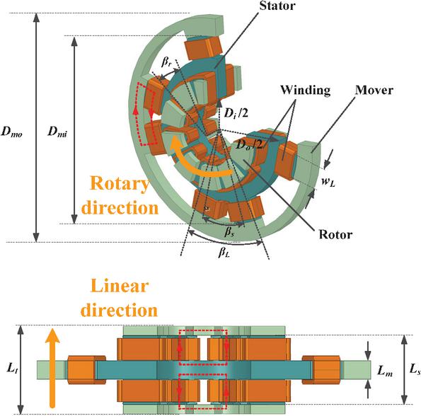
Figure 1 3D views of proposed TLRSRM model.
Additionally, the red dashed lines in Fig. 1 represent magnetic flux paths. It can be observed that the rotating section adopts an axial flux disc structure, where the rotor poles and axially symmetric stator teeth form the main magnetic circuit. This circuit closes through the stator yoke, achieving a uniform axial magnetic field distribution. The interaction between the three-phase concentrated windings and the rotor poles generates electromagnetic torque to drive rotation. The linear section operates similarly to conventional transverse flux motors. Magnetic flux lines originate from the stator yoke, traverse the stator poles and air gap, and form a radially closed circuit through the rotor ferromagnetic ring. The reverse winding generates an alternating-polarity magnetic field, establishing multiple independent magnetic circuits in the radial plane. These closed magnetic circuits run parallel to the stator cross-section and perpendicular to the rotor’s direction of motion.
When the windings are energized, electromotive forces (EMF) are simultaneously induced on both the rotor and stator surfaces of the TLRSRM, thereby establishing independent current loops. These loops generate rotational torque and axial thrust concurrently. This integrated electromechanical design allows the motor to execute combined rotary-linear motion in both motoring and generating operational modes.
Based on the design experience of conventional axial flux SRMs and radial switched reluctance linear motors [16], the structural parameters of the TLRSRM of this paper are shown in Table 1.
Table 1 Structure parameters of the TLRSRM
| Item | Unit | Value |
| Rated power | kW | 1.5 |
| Mover outer diameter/ | mm | 360 |
| Mover inner diameter/ | mm | 300 |
| Stator yoke outer diameter/ | mm | 230 |
| Stator yoke inner diameter/ | mm | 101 |
| Linear stator pole width/ | mm | 40 |
| Linear stator pole length/ | mm | 20 |
| Stator stack length/ | mm | 74 |
| Motor stack length/ | mm | 94.8 |
| Rotor pole arc/ | deg | 25 |
| Linear mover pole arc/ | deg | 45 |
| Linear stator tooth pitch/ | deg | 30 |
| Linear air gap thickness | mm | 0.5 |
| Rotary air gap thickness | mm | 0.8 |
| Winding conductor diameter | mm | 2 |
3 STATIC ANALYSIS OF TLRSRM
In this paper, the flowchart of 3D modeling and analysis of the TLRSRM system using finite element software ANSYS is shown in Fig. 2 with the following steps.
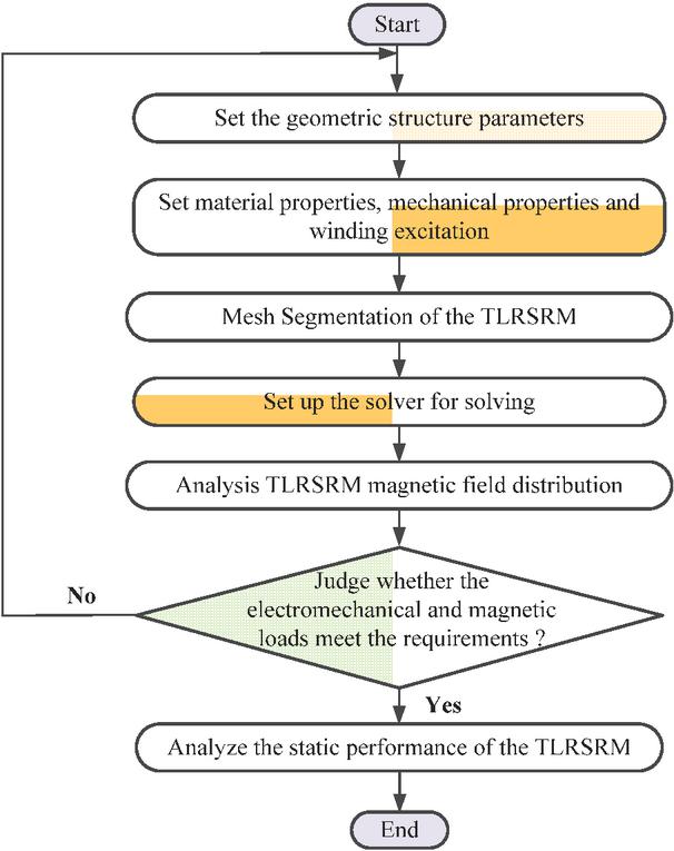
Figure 2 Flow chart of finite element analysis.
• A geometric model of the TSRLM is established based on the pre-determined geometric dimension table. The geometric parameters in the model were configured according to the motor dimension specifications, ensuring precise mapping of the physical structure into the digital model.
• Physical properties of the TSRLM are set, including mechanical properties, material properties, and winding excitation of each component of the TSRLM.
• A customized mesh dissection of the TSRLM is performed and the geometric properties, physical properties, and dissection of the finite element model (FEM) are examined.
• A suitable solver (e.g., Maxwell 3D static/dynamic solver) is configured to perform electromagnetic field calculations on the meshed model. Then 3D magnetic flux distribution is analyzed to evaluate whether the designed electric load (current density, ) and magnetic load (core flux density) meet design specifications. Specifically, the stator/rotor core flux density is checked against the saturation threshold (typically 1.8 T for silicon steel) to avoid excessive iron loss and magnetic nonlinearity, ensuring the motor operated within the optimal magnetic working range.
• After obtaining a well-designed motor structure, the FEM of TSRLM is analyzed for static performance and the data obtained from the simulation is processed in the next step.
Equal scale 3D FEM of the TLRSRM proposed in this paper from point to line and surface is performed according to the structural dimension in Table 1. The results of the mesh dissection of the geometric model of the TLRSRM are shown in Fig. 3. It can be observed that the mesh density in the FEM is custom adjusted according to the magnetic field distribution characteristics. Specifically, regions with complex magnetic field gradients (including stator pole tips, edges of the kinematic yoke, and air gap) are assigned fine meshes to capture rapid spatial variations in magnetic flux density and magnetic force. These critical regions, which are prone to magnetic saturation and field distortion, require high-resolution discretization to ensure accurate electromagnetic field calculations. In contrast, regions with relatively uniform or low magnetic field strengths (e.g., unsaturated cores and mechanical supports) employ coarser meshes to balance computational efficiency and solution accuracy.
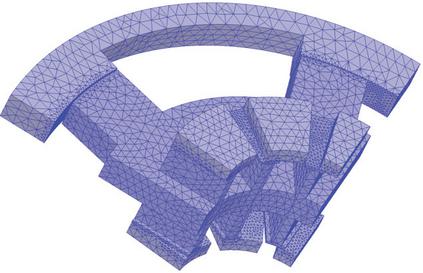
Figure 3 Mesh sections for the 1/4 model of the TLRSRM.
In rotary motion, when one of the phase windings is energized, the rotor position goes from unaligned to aligned, rotating one cycle in the angular range of (, ). In linear motion, excited by current from a single-phase winding, the actuator travel can be 20 mm to 0 mm or 0 mm to 20 mm, defining the position where the actuator’s ferromagnetic ring and stator are fully aligned as the 0 mm position. The 20 mm position is the point at which the movable element moves negatively in the axial direction by 20 mm, and the movable element ferromagnetic ring and stator are perfectly misaligned when the movable element is in this position.
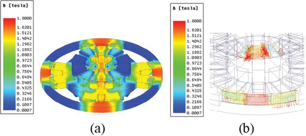
Figure 4 TLRSRM in aligned position: (a) magnetic flux density map and (b) flux linkage distribution.
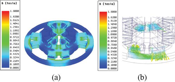
Figure 5 TLRSRM in unaligned position: (a) magnetic flux density map and (b) flux linkage distribution.
Figures 4 and 5 show the magnetic field distribution in the aligned and unaligned positions of the motor at rated operating conditions. Included here are the stator and rotor in rotational motion, and the stator and mover in linear motion. It can be seen that, when in the aligned position, there is less air leakage and the magnetic chain passes almost entirely through the rotor/motor. The air gap and the stator poles to form a closed loop, at which time the magnetic induction intensity in all parts of the TLRSRM reaches its maximum value. The motor has a high magnetic flux density, especially in the stator tooth poles and the magnetically conductive yoke section of the mover, with a high degree of core saturation. The maximum value of stator-rotor magnetic density is about 1.7 T, which meets the design requirements. From the same direction of flux flow at the air gap in Fig. 4 (b), it can be seen that the stator and rotor are more saturated at the air gap contact area, which is due to the smaller contact area. From Fig. 5, it is clearly observed that the overall core of the motor is less saturated with magnetic density, which is due to the inability of the flux path generated by the windings to form a closed path in the core. In linear motion, the area of the stator and the mover in the air gap contact area is almost zero, and there is more air leakage. In rotary motion, the air gap length between neighboring rotor blocks is too large, and the reluctance is larger.
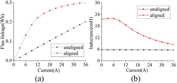
Figure 6 Static characteristics of rotary motion: (a) flux linkage at critical locations and (b) inductance at critical locations.
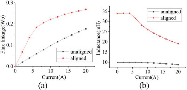
Figure 7 Static characteristics of linear motion: (a) flux linkage at critical locations and (b) inductance at critical locations.
Figures 6 and 7 illustrate the variations in magnetic flux linkage and phase inductance of the motor at two critical rotor positions: the unaligned and aligned configurations. For these measurements, a representative phase winding was selected for the rotating component, while a pair of stator pole windings was chosen for the linear section. At low excitation currents, the flux linkage exhibits a linear increase with current, and the inductance remains approximately constant at both positions, indicating that the magnetic circuit operates within the linear region of the core material’s B-H curve. However, as the current exceeds the saturation threshold, the flux linkage at the aligned position begins to deviate from linearity, and the inductance gradually decreases. In contrast, the unaligned position shows no significant change in either parameter, maintaining linear behavior even at higher currents. This discrepancy arises because the aligned position experiences higher magnetic flux density in the stator and rotor cores, leading to localized saturation as the current increases. Once the core material reaches its saturation point (typically 1.8–2.0 T for silicon steel), the rate of change of magnetic flux with respect to current diminishes, resulting in the observed nonlinearity in flux linkage and inductance.
To comprehensively analyze the static characteristics across all rotor positions, Figs. 8 and 9 present 3D surface plots of inductance and flux linkage as functions of both current and rotor position, using the rotational motion as a case study. These plots reveal that the flux linkage exhibits a consistent trend with respect to rotor position across different current levels, indicating that the spatial distribution of the magnetic field is preserved despite variations in excitation magnitude.
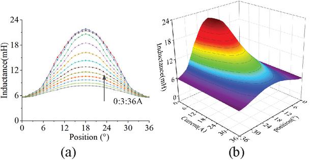
Figure 8 Variation of inductance characteristics in rotary motion: (a) 2D variation curve and (b) 3D variation curve.
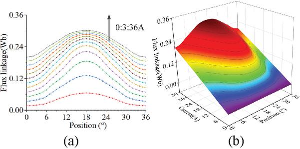
Figure 9 Variation of flux linkage characteristics in rotary motion: (a) 2D variation curve and (b) 3D variation curve.
Based on 3D finite element static simulations, the electromagnetic output characteristics of the two-degree-of-freedom TLRSRM are systematically analyzed as functions of rotor/stator position and excitation current, with the results presented in Figs. 10 and 11. Regarding the rotary motion characteristics, the static torque curve indicates that, as the rotor rotates from the unaligned to the aligned position, the electromagnetic torque exhibits a typical nonlinear pattern, initially rising and then falling. Specifically, at a rotor position angle of , where the rotor pole centerline coincides with the stator slot centerline, the rate of change of inductance reaches its peak and the magnetic reluctance is maximized, resulting in the maximum electromagnetic torque. Conversely, at the position, complete alignment between the stator and rotor poles minimizes the magnetic reluctance, causing the electromagnetic torque to drop to zero. This behavior is consistent with the fundamental operating principle of SRMs.
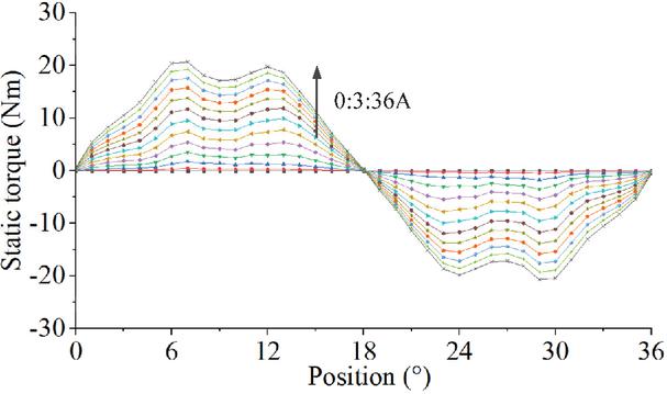
Figure 10 Static torque curve for rotary motion.
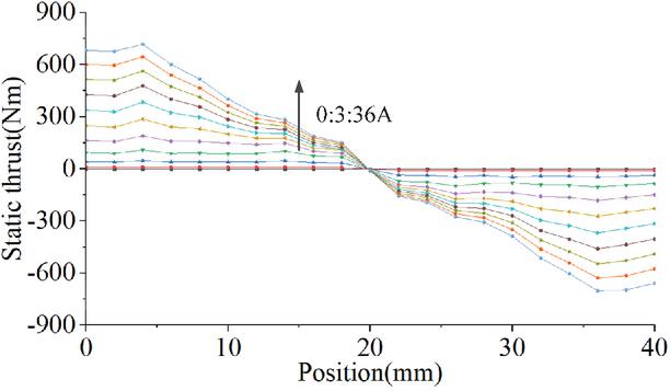
Figure 11 Static thrust curves for linear motion.
In terms of linear motion characteristics, the static thrust curve shows a similar trend to that of rotary motion, which verifies the consistency of the electromagnetic force generation mechanism of this motor under multi-degree-of-freedom motion. Thanks to the accurate modeling of the motor end effect by the 3D finite element method, the static electromagnetic force results obtained from the simulation have high accuracy and reliability. Further parametric analysis shows that, with the increase of the excitation current, the curve shape of the electromagnetic force with respect to the position remains stable, but its amplitude tends to increase significantly. It is worth noting that when the excitation current exceeds a certain threshold, the growth rate of the electromagnetic force with the current gradually slows down due to the gradual saturation of the motor core, which is a characteristic that needs to be paid attention to in practical engineering design to avoid the performance degradation brought about by the saturated core. The above results not only reveal the changing law of electromagnetic force of TLRSRM under multi-degree-of-freedom motion, but also provide an important theoretical basis for the optimization design of the motor and the development of control strategies.
To further investigate the coupling effect between the linear and rotary windings on the motor’s torque performance, the influence of energized linear windings on rotary motion is analyzed as an example. Figure 12 (a) shows the static torque variation when only the linear windings are supplied with rated current and the mover is in the aligned position. Figure 12 (b) illustrates the average static torque of the rotary motion under different excitation states of the linear windings, including no excitation, double excitation, and reverse excitation. Additionally, Fig. 12 (c) presents the electromagnetic torque variation of the rotary motion when the linear windings are supplied with rated current while the rotary windings are not excited.
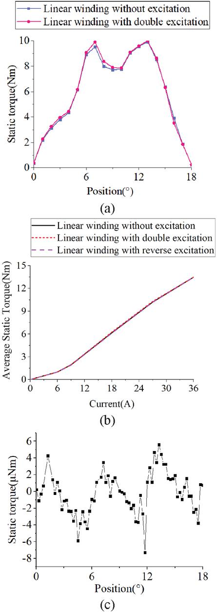
Figure 12 Flux density distribution of TLRSRM: (a) static torque waveform, (b) static average torque variation with different currents, and (c) static torque of the linear winding under rated excitation with the rotary winding de-energized.
As can be seen from Fig. 12 (a), the rotary torque waveform generated by the rotary windings remains almost unchanged regardless of whether the linear windings are excited. Additionally, it can be observed that under the excitation of the linear winding current and with no excitation applied to the rotary winding, the peak-to-peak value of the rotary torque is approximately 12 Nm. Therefore, when only the linear winding is supplied with the rated current and the mover is in the aligned position, the influence of the linear winding on the rotary motion is minimal, indicating a low coupling effect.
4 DYNAMIC PERFORMANCE ANALYSIS OF TLRSRM
To further evaluate the transient driving capabilities and multi-degree-of-freedom operational performance of the proposed TLRSRM, a comprehensive dynamic system model is established in MATLAB/Simulink. To retain the highly non-linear electromagnetic characteristics of the machine while ensuring computational efficiency, two-dimensional look-up tables (2D LUTs) of the non-linear flux linkage and static electromagnetic forces (torque and thrust) obtained from the prior analysis are implemented into the dynamic solver.
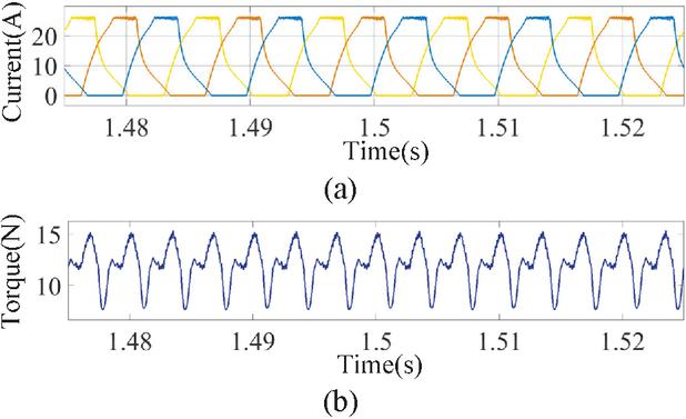
Figure 13 Dynamic performance of rotary motion at 600 : (a) phase current waveform and (b) torque waveform.
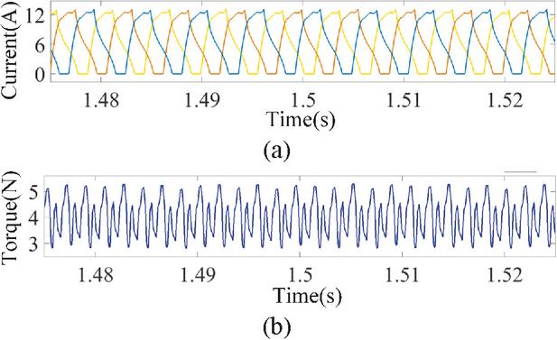
Figure 14 Dynamic performance of rotary motion at 1000 : (a) phase current waveform and (b) torque waveform.
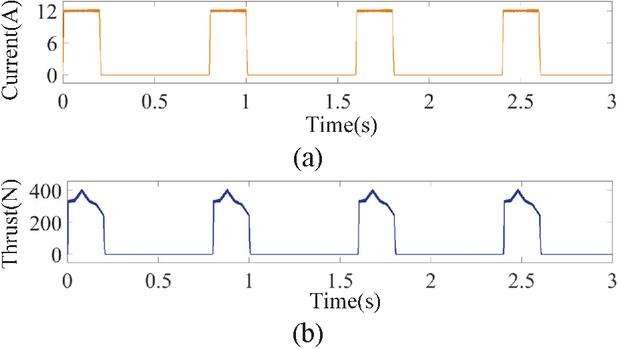
Figure 15 Fig. 15. Dynamic performance of linear motion at 0.05 : (a) phase current waveform and (b) thrust waveform.
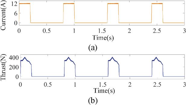
Figure 16 Dynamic performance of linear motion at 0.1 : (a) phase current waveform and (b) thrust waveform.
The transient dynamic performance of the rotary motion is investigated under two typical control modes, namely current chopping control (CCC) and single pulse control (SPC). Under the CCC mode, the machine operates at a low rotational speed of 600 r/min with a preset rated chopping current of 15 A, and the corresponding transient phase current and dynamic torque waveforms are illustrated in Fig. 13. Under the high-speed SPC mode, the machine runs at 1000 r/min under an adjustable load torque of 4 Nm, where the phase current exhibits a typical single-pulse waveform shape due to the elevated back EMF, as shown in Fig. 14. For a fair comparison, both operational modes are configured with a DC bus voltage of 96 V and identical turn-on and turn-off angles. The simulation results demonstrate that the dynamic torque effectively tracks the command values with acceptable ripples, verifying the excellent rotational drive capability.
Similarly, the transient dynamic characteristics of the linear motion are evaluated at different mover translation speeds of 0.05 m/s and 0.1 m/s. For both speed configurations, a DC bus voltage of 96 V and identical turn-on and turn-off positions are maintained. Figures 15 and 16 display the transient single-phase current and dynamic thrust waveforms, respectively. It can be observed that a reliable and robust dynamic thrust output is consistently maintained, which proves the feasibility of the linear actuation.
5 CONCLUSION
This study investigates the electromagnetic characteristics of a novel two-degree-of-freedom TLRSRM. By combining 3D finite element parameter sweeps with system-level Simulink dynamic simulations, the structural feasibility and operational rationality of the proposed topology are comprehensively verified. Under low excitation, the inductance and flux linkage exhibit near-linear behavior, whereas localized magnetic saturation under high currents introduces distinct nonlinear characteristics at the aligned position. Furthermore, the electromagnetic cross-coupling effect between the rotary and linear sections is quantitatively analyzed.
The dynamic performance further demonstrates the robust driving capabilities of the machine under typical control schemes. In the rotary mode, the phase currents and dynamic torque effectively track the operational demands under both CCC (600 r/min, 15 A) and SPC (1000 r/min, 4 Nm) modes with identical turn-on and turn-off angles. In linear mode, reliable and stable dynamic thrust outputs are consistently maintained at translation speeds of 0.05 m/s and 0.1 m/s under a 96 V DC bus voltage. Characterized by a compact structure and efficient electromagnetic performance, this TLRSRM framework provides a solid theoretical foundation for subsequent optimization and shows significant potential in advanced applications such as marine energy utilization.
ACKNOWLEDGMENT
This work is supported by the National Natural Science Foundation of China International (regional) cooperation and exchange projects NSFC-RSF under Grant W2412064 and the Shenzhen Collaborative Innovation Special Plan International Cooperation Research Project under Grant GJHZ20240218114300002.
REFERENCES
[1] H. Chen, R. Nie, and X. Li, “A transverse-flux single-phase tubular switched reluctance linear machine with 4 poles,” IEEE Transactions on Applied Superconductivity, vol. 31, no. 8, pp. 1–4, Nov. 2021.
[2] K. Manohar and K. Srichandan, “Analysis of quadrupole magnetic field reluctance-based launcher with different coil switching patterns,” IEEE Transactions on Plasma Science, vol. 51, no. 5, pp. 1370–1376, May 2023.
[3] L. Zhang, L. Yan, X. Wei, H. Su, Z. Dong, and L. Li, “Stress analysis of a flat linear switched reluctance motor with double excitation windings,” in CSAA/IET International Conference on Aircraft Utility Systems, Nanchang, China, pp. 1240–1245, 2022.
[4] W. Ding, H. Fu, and Y. Hu, “Characteristics assessment and comparative study of a segmented-stator permanent-magnet hybrid-excitation SRM drive with high-torque capability,” IEEE Transactions on Power Electronics, vol. 33, no. 1, pp. 482–500, Jan. 2018.
[5] R. Nie, J. Si, Y. Jia, P. Wang, S. Xu, and J. Liang, “Comprehensive comparison of mover-PM and stator-PM linear-rotary generators for wind-wave combined energy conversion system,” IEEE Transactions on Industry Applications, vol. 60, no. 4, pp. 6170–6185, July-Aug. 2024.
[6] H. Chen, Y. Zhan, and R. Nie, “Multiobjective optimization design of single-phase tubular switched reluctance linear launcher,” IEEE Transactions on Plasma Science, vol. 47, no. 5, pp. 2431–2437, May 2019.
[7] H. Chen, R. Nie, and H. Wang, “A transverse flux single-phase tubular-switched reluctance linear launcher with eight-pole structure,” IEEE Transactions on Plasma Science, vol. 47, no. 5, pp. 2331–2338, May 2019.
[8] D. Wang, C. Shao, X. Wang, and C. Zhang, “Performance characteristics and preliminary analysis of low-cost tubular linear switch reluctance generator for direct drive WEC,” IEEE Transactions on Applied Superconductivity, vol. 26, no. 7, pp. 1–5, Oct. 2016.
[9] D. H. Wang, X. H. Wang, C. L. Shao, and L. X. Xiong, “Design aspects of a high thrust density dual stator yokeless linear switched reluctance machine for harsh conditions,” in 2015 IEEE International Conference on Applied Superconductivity and Electromagnetic Devices, Shanghai, China, pp. 468–469, 2015.
[10] H. Chen, Z. Li, W. Yan, and R. Nie, “Flux characteristics analysis of a single-phase tubular switched reluctance linear launcher based on 3D magnetic equivalent circuit,” IEEE Transactions on Plasma Science, vol. 47, no. 5, pp. 2507–2513, May 2019.
[11] S. Xu, X. Jiang, J. Si, R. Nie, and P. Wang, “A two-degree-of-freedom double-stator linear-rotary switched reluctance motor for an industrial robot,” in 2023 26th International Conference on Electrical Machines and Systems, Zhuhai, China, pp. 3666–3671, 2023.
[12] W. Wu, J. B. Dunlop, S. J. Collocott, and B. A. Kalan, “Design optimization of a switched reluctance motor by electromagnetic and thermal finite-element analysis,” IEEE Transactions on Magnetics, vol. 39, no. 5, pp. 3334–3336, Sep. 2003.
[13] S. Zhao, H. Chen, R. Nie, and J. Liu, “Multi-objective optimal design of double-sided switched reluctance linear generator for wave power generation,” Compel, vol. 38, no. 6, pp. 1948–1963, 2019.
[14] H. Chen, Y. Zhan, H. Wang, and R. Nie, “A tubular permanent magnet linear generator with novel structure,” IEEE Transactions on Plasma Science, vol. 47, no. 6, pp. 2995–3001, June 2019.
[15] S. Xu, X. Jiang, J. Si, R. Nie, and P. Wang, “A two-degree-of-freedom double-stator linear-rotary switched reluctance motor for an industrial robot,” in 26th International Conference on Electrical Machines and Systems (ICEMS), Zhuhai, China, pp. 3666–3671, 2023.
[16] F. Yu, H. Chen, W. Yan, V. F. Pires, J. F. A. Martins, P. Rafajdus, A. Musolino, L. Sani, M. P. Aguirre, M. A. Saqib, M. Orabi, and X. Li, “Design and multiobjective optimization of a double-stator axial flux SRM with full-pitch winding configuration,” IEEE Transactions on Transportation Electrification, vol. 8, no. 4, pp. 4348–4364, Dec. 2022.
BIOGRAPHIES

Cheng Liu received the B.S. degree in electrical engineering and automation from Hubei University of Technology, Wuhan, Hubei, China, in 2020, and the M.S. degree in electrical engineering from Hubei University of Technology, Wuhan, Hubei, in 2023. He is currently pursuing a Ph.D. degree in electrical engineering at China University of Mining and Technology, Xuzhou. His research interests include switched reluctance motor design control, ocean wave power generation, and electric vehicles.

Hao Chen (SM’08) received the B.S. and Ph.D. degrees from the Department of Automatic Control, Nanjing University of Aeronautics and Astronautics, Nanjing, China, in 1991 and 1996, respectively. In 1998, he became an Associate Professor with the School of Information and Electrical Engineering, China University of Mining and Technology, Xuzhou, where he has been a Professor since 2001. From 2002 to 2003, he was a Visiting Professor at Kyungsung University, Busan, Korea. Since 2008, he has also been an Adjunct Professor at the University of Western Australia, Perth, Australia. He is the author of one book and has also authored more than 190 papers. He is the holder of 15 US Patents, 23 Australian Patents, one Danish Patent, seven Canadian Patents, three South African Patents, 10 Russian Patents, 86 Chinese Invention Patents, and six Chinese Utility Model Patents. His current research interests include motor control, linear launcher, electric vehicles, electric traction, servo drives, and wind power generator control.
Chen was the recipient of both the Prize of Science and Technology of Chinese Youth and the Prize of the Fok Ying Tong Education Foundation for Youth Teachers in 2004. He was awarded first prize in the Science and Technology advanced of Province and Ministry once, second prize in the Science and Technology advanced of Province and Ministry seven times, and third prize in Science and Technology Advanced of Province and Ministry 14 times. He became the Chinese New Century Hundred-Thousand Ten-Thousand Talents Engineering National Talent in 2007, and won the Government Especial Allowance of People’s Republic of China State Department since 2006.

Marcin Wardach was born in Poland in 1980. He graduated and received the Ph.D. degree from the Electrical Department, Szczecin University of Technology, Szczecin, Poland, in 2004 and 2009, respectively. From 2020 until now, he has served as Associate Professor with the Faculty of Electrical Engineering, West Pomeranian University of Technology, in Szczecin. Since 2024, he has served as Vice-Dean for Organization and Development and Head of the Department of Electrical Machines and Drives at the Faculty of Electrical Engineering, West Pomeranian University of Technology, in Szczecin. From 2019 to 2025, he worked as an electrical machine designer at mPower Sp. z o.o. company. His research interests include the design of electrical machines and drives, especially unconventional and hybrid excited. He is the author of over 100 scientific papers and post-conference publications. Since 2022, he has been President of the Szczecin Branch of the Association of Polish Electrical Engineers (SEP). He is also a member of the Polish Society of Theoretical and Applied Electrical Engineering.

Javokhir Toshov currently works at the Department of Mining Electromechanics, Tashkent State Technical University, Uzbekistan. Javokhir does research in Mechanical Engineering and Mining Engineering in the Department of Electronic Devices Manufacturing Technologies, Faculty of Electronic and Automation Engineering, Tashkent State Technical University, Tashkent 100095, Uzbekistan; Department of Theoretical and Experimental Physics, Faculty of Physics, Karshi State University, Karshi 180119, Uzbekistan.

Xing Wang received the B.S. degree from China University of Mining and Technology, Xuzhou Jiangsu, China, in 1996, and M.S. degree from China University of Mining and Technology, Xuzhou Jiangsu, in 1999. In 2007, she became an Associate Professor with China University of Mining and Technology, Xuzhou. She is a holder of four US Patents, nine Australian Patents, two Canadian Patents, four Russian Patents, 12 Chinese Invention Patents, three Chinese Utility Model Patents, and has authored 15 papers.

Bodrenkov Evgenii Alexandrovich received the B.S. and M.S. degree from Federal State Budgetary Educational Institution of Higher Education, Amur State University, and Ph.D. degrees from Federal State Autonomous Educational Institution of Higher Education, Peter the Great St. Petersburg Polytechnic University.

Popov Stanislav Olegovich received the M.S. degree in the field of “Electric power plants and automation of power systems” in 2008, and Ph.D. in Technical Sciences. He has been an associate professor at the Institute of Energy, from 2008 to present in SPBSTU.

Nikolay Korovkin (Member, IEEE) received the M.S., Ph.D., and Doctorate degrees in electrical engineering from the State Polytechnic University, Saint Petersburg, Russia, in 1977, 1984, and 1995, respectively. He is currently a Professor with the Institute of Energy, Peter the Great Saint Petersburg Polytechnic University, Saint Petersburg. Since 1996, he has been an Academician with the Academy of Electrotechnical of Russian Federation, Saint Petersburg. He has about 300 published and reviewed works in Russia and abroad. His main research interests include the inverse problems in electromagnetics, systems described by stiff equations, ill conditioned problems, optimization of power networks, optimization of the location FACTS and PMU-devices, SMART grid technologies, methods for the analysis of reliability and ensuring power balance in EPS, methods of multicriteria optimization and their application to steady-state processes in power networks, transients in transmission line systems, impulse processes in linear and nonlinear systems, problems of the electromagnetic prediction of earthquakes, and identification of the behavior of the biological objects under the influence of the electromagnetic fields.

Sakhno Liudmila (Member, IEEE) received the B.S., M.S., and Ph.D. degrees from Russia Polytechnic Institute, Saint Petersburg, Russia, in 1972, 1974, and 1982, respectively, and the Doctorate degree in electromechanics and electrical apparatus from St. Petersburg State Technical University, Saint Petersburg, in 2006. She is currently a Professor of Higher School of High Voltage Power Engineering, Peter the Great Saint Petersburg Polytechnic University, Saint Petersburg. She has about 200 published and reviewed works in Russia and abroad. Her research interests include the electromagnetic problems in power transformers, the skin effect and the proximity effect in the windings of converter transformers, electromagnetic and thermal characteristics of arc and resistance welding transformers, mechanical strength of structural elements under the action of loads, and field-circuit modeling in high frequency resistance spot welding systems. She has eight Russian Federation Patents.

Mohamed Orabi (Senior Member, IEEE) received the Ph.D. degree in power electronics from Kyushu University, Fukuoka, Japan, in 2004. He is currently a Professor with the Department of Electrical Engineering, Faculty of Engineering, Aswan University, Aswan, Egypt, where he is also the Founder and the Director of the Aswan Power Electronics Application Research Center. He is the Deputy Dean for the Postgraduate Studies and Research. His current research interests include high-frequency DC-DC converters and power factor correction converters for LEDs and electric vehicles applications, integrated power management, analysis and modeling of nonlinear circuits, and inverter control and design for renewable energy applications. Orabi was the Chair of the IEEE Power Electronics Egypt Chapter until 2020. He is a Guest Editor for IEEE Journal of Emerging and Selected Topics in Power Electronics.

Mahmoud A. Gaafar (Senior Member, IEEE) received the B.Sc. and M.Sc. degrees in electrical engineering from Aswan University, Aswan, Egypt, in 2004 and 2010, respectively, and the Ph.D. degree in electrical and electronics engineering from Kyushu University, Fukuoka, Japan, in 2017. In 2017, he joined the Aswan Power Electronics Applications Research Center (APEARC), Aswan University. He is currently an Assistant Professor with the Department of Electrical Engineering, Faculty of Engineering, Aswan University. He has been involved in several projects related to power electronics applications. His current research interests include the design and control of power electronics converters for photovoltaic, motor drives, and battery-based systems. Gaafar is also a member of the IEEE Power Electronics Society. He was a recipient of the Baek-Hyun Award in 2018 from the Korean Institute of Power Electronics for his academic contribution to the field of power electronics.

Emmanuel Karapidkis is an Electrical and Computer Engineer. He was Dean at School of Engineering from 2019 to 2025, and Director of Energy, Environment and Climate Change Institute – IEECC (http://ieecc.hmu.grieecc.hmu.gr) in Hellenic Mediterranean University HMU (http://hmu.grhmu.gr). Since 2022, he has been President of the Board in Hellenic Association of Electricity Storage Systems – HAESS (http://www.haess.grwww.haess.gr). His research interests focus on energy systems, power systems operation, diverse & dispersed generation, micro-grids, renewable energy technologies, energy storage, and energy markets. He is/was scientific coordinator (PI) in 12 European financed projects, 15 National programs and several private funded projects, with more than 8 million euros in total. He has published more than 120 papers (Scopus Author ID 6506872824) in prestigious journals and scientific conferences, and four scientific book chapters. From 2011 to 2015, he was a Member of the Board in Regional Council of Innovation, and from 2015 to 2017, Member of the Board in Energy Planning Council at Region of Crete.

Aris Evangelos Dimeas is an Assistant Professor at the School of Electrical and Computer Engineering of the National Technical University of Athens (NTUA), with more than 20 years of experience in power systems operation, smart grids, and energy system digitalization. His expertise spans distribution and transmission system operation, renewable energy integration, microgrids, flexibility markets, artificial intelligence applications, and advanced control and decision-support software. He has played a leading technical and coordination role in more than 30 EU-funded research and innovation projects (H2020 and Horizon Europe), collaborating closely with TSOs, DSOs, regulators, industry, and the European Commission. His work bridges research and real-world deployment, with demonstrated impact on system supervision, resilience, market design, and data-driven grid operation, while his scientific contributions include high-impact publications in leading IEEE and international journals.

Sherif Moussa is Dean of the School of Engineering, Applied Science, and Technology at the Canadian University Dubai (CUD), UAE. He earned his Ph.D. in Electrical and Computer Engineering from the University of Québec at Trois-Rivières, Canada, and his M.Sc. in Electrical and Computer Engineering from the University of Waterloo, Canada. Since joining CUD in 2007, Moussa has led the School’s remarkable growth, overseeing the launch and accreditation of several engineering and computing programs, including mechatronics engineering, computer science, cybersecurity, software design, power and renewable energy engineering, and the M.Sc. in Artificial Intelligence. His leadership has also advanced international collaborations, notably with Queen’s University and the University of Ottawa, and strengthened CUD’s engagement with industry partners in emerging technologies. Moussa’s research interests span wireless communication, computer networks, machine learning, and digital systems design. He has published widely in international journals and conferences, serves on technical committees, and is the recipient of the 2015 CUD Research Excellence Award. He is also the founder of CUD’s Robotics Club and a strong advocate for innovation and experiential learning in engineering education.

Habes Ali Khawaldeh (Member, IEEE) received the B.E. degree in electrical and computer engineering from The Hashemite University, Jordan, in 2009, and the M.S. degree in electrical power engineering from Yarmouk University, Jordan, in 2013. In 2022, Habes Ali Khawaldeh received his Ph.D. degree in power electronics engineering from the Faculty of Engineering and Information Technology, University of Technology Sydney (UTS), Australia. Since 2018, he has been a Casual Academician with UTS for various power electronics subjects. Since July 2009, he has been working as an electrical engineer with different companies in Jordan. He was a part-time Faculty Member with Yarmouk University for various power electronics subjects. He was a full-time Faculty Member with Al-Hussein Bin Talal University from 2015 to 2018. His current research interests include renewable energy (RE) systems, power converter design for RE applications, battery systems, multi-port DC/DC converters, and energy conversion systems for the smart grid. He received a Grant from Al al-Bayt University for his Ph.D. degree. He is currently a reviewer for several IEEE, IET, and Elsevier journals. Currently, Habes Ali Khawaldeh is an assistant professor at the University of Al al-Bayt in Jordan.
ACES JOURNAL, Vol. 41, No. 6, 512–523
DOI: 10.13052/2026.ACES.J.410603
© 2026 River Publishers