Comparative Analysis of Microstrip Patch Antenna Performance on Various Dielectric Substrates
Fatih Göksel1 and Saeid Karamzadeh1, 2
1Electrical and Electronics Engineering Department Faculty of Engineering and Natural Sciences, Bahçeçehir University İstanbul, Tükiye
fatih.goksel@bahcesehir.edu.tr
2Millimeter Wave Technologies Intelligent Wireless System, Silicon Austria Labs (SAL), 4040 Linz, Austria
saeid.karamzadeh@silicon-austria.com
Submitted On: January 16, 2026
Accepted On: May 08, 2026
ABSTRACT
Microstrip patch antennas (MSPAs) have gained significant popularity due to their compact size, ease of fabrication, low cost, lightweight construction, and compatibility with planar and non-planar surfaces. The aim is to identify the optimal substrate for a designed MSPA by comparing the performance of six different substrates. Accordingly, both rectangular MSPA and circular MSPA (CMSPA) have been developed and simulated by using six different substrates: FR4 Glass Epoxy, ROGERS DT5880, ROGERS 4003C, Teflon, Arlon AD300A, and Alumina with thickness of 1.6 mm and 1 mm. Rectangular and CMSPAs have been fabricated and measured to verify the effects of the substrates. The proposed antenna is designed to achieve resonance at the target frequency of 5.8 GHz. This study offers valuable insights into the performance of MSPAs with various substrates, thereby assisting researchers in selecting the most appropriate materials for their designs.
Keywords: Antenna efficiency, antenna gain, dielectric substrate, impedance bandwidth, microstrip patch antenna..
1 INTRODUCTION
An antenna is a critical component in wireless communication systems, responsible for radiating and receiving electromagnetic waves to enable efficient signal transmission. Its performance is primarily governed by parameters such as operating frequency, impedance matching, radiation efficiency, bandwidth, and physical dimensions. Among various antenna types, microstrip patch antennas (MSPAs) have become increasingly significant due to their low profile, lightweight structure, ease of integration with printed circuit boards, and cost-effectiveness. MSPAs typically consist of a metallic patch mounted on a dielectric substrate with a ground plane, supporting modes such as for fundamental operation. Despite their advantages, MSPAs exhibit limitations like narrow bandwidth and relatively low gain, which have driven research into techniques such as slotting, stacking, and the use of high-permittivity substrates to enhance performance. The concept of microstrip radiators was first introduced by Deshalbs in 1953 [1], followed by a patent granted to Gutton and Baissinot in France in 1955 [2]. Substantial development occurred after 1970, particularly for aerospace and military applications where size, weight, and reliability were critical [1].
A conventional MSPA comprises a radiating patch, a dielectric substrate, and a ground plane. The dielectric constant of the substrate typically ranges between 2.2 and 12, significantly influencing radiation characteristics, efficiency, and bandwidth. For compact microwave systems, particularly in miniaturized devices, the use of a thin substrate with a high dielectric constant is generally preferred to mitigate undesired radiation and coupling effects while maintaining structural compactness. Microstrip antennas present several inherent advantages, including a low-profile structure, reduced weight, ease of fabrication, conformal adaptability, cost-effectiveness, and seamless integration with microwave circuits. Nevertheless, these antennas exhibit certain limitations, such as reduced radiation efficiency, susceptibility to feed and junction radiation, excitation of surface waves, restricted impedance bandwidth, and increased sensitivity to manufacturing tolerances. Key design parameters include the width of the patch (Wp), length of the patch (Lp), effective permittivity (), inset feed depth (Fi), and the directivity of the antenna [3, 4] Additionally, denotes the relative permittivity of the substrate, while Wf represents the width of the inset feedline, designed to maintain a microstrip line impedance of [5].
Several studies have investigated the performance of different substrates utilized in microwave applications. A study investigated a 5G microstrip antenna using FR4, Rogers RO4350B, and Arlon AD255C, focusing on directivity and bandwidth based on permittivity to operate at 60 GHz. The findings suggest that the Rogers RO4350B substrate may exhibit favorable directivity performance at the specified thickness [6]. Another study analyzed five different substrates: Bakelite, FR4, RO4003, Taconic TLC, and RT/Duroid with a uniform substrate thickness of 1.5 mm which focused on a resonant frequency of 10 GHz. Among the substrates evaluated, RT/Duroid demonstrated superior performance, achieving 80% efficiency and 15% bandwidth. Furthermore, RT/Duroid exhibited an impressive return loss of 20.99 dB, positioning it as a favorable choice compared to the other substrates for MSPAs [7]. Additionally, research utilizing Rogers RT/Duroid 5880 with a dielectric constant of 2.2 and a thickness of 0.508 mm focused on designing a dual-band compact antenna for sub-6 GHz 5G applications, simulating performance in both onbody and free-space scenarios. These findings collectively highlight the growing relevance of substrate properties, such as dielectric constant, loss tangent, and thickness, in optimizing antenna performance for emerging technologies like 5G [8].
The growing demand for flexible wireless systems has made antenna design on ultra-thin flexible substrates increasingly significant. This study examines whether substrate thickness and dielectric constant play a critical role during the initial design stage of antennas. Measurements conducted on three flexible antenna prototypes fabricated using materials such as Rogers and polyimide were compared. The results indicate that the substrate is not merely a supporting structure; it must be considered for accurate prediction of feeding structure performance and resonant frequencies. Furthermore, manual mesh refinement is essential to achieve simulation results that closely match measurements, particularly for ultra-thin substrates [9].
A simplified method for estimating dielectric properties, relative permittivity () and dissipation factor , using a single open-ended microstrip line has been introduced. Unlike traditional dual-line approaches, this technique reduces complexity and cost while providing accurate results for thin substrates. Based on transmission line theory, it incorporates an iterative algorithm for loss estimation without requiring prior knowledge of conductor or radiation losses. Validation on FR-4, Rogers RT6010, and LDPE shows good agreement with reference values for low- and medium-permittivity materials, though accuracy decreases for high-permittivity, low-loss substrates. The method offers a practical solution for rapid dielectric characterization in RF and microwave design [10].
In [11], the Rogers 4003 substrate is used with a dielectric constant of 3.55 for wide-angle frequency scanning and to increase the gain of the antenna. As a result, the size of the antenna decreased, and the gain was increased to 18.8 dBi.
Six dielectric substrates including FR4 Glass Epoxy, Rogers DT5880, Rogers RO4003C, Teflon, Arlon AD300A, and Alumina were compared for designing a rectangular MSPA operating at 5.8 GHz with a fixed thickness of 1.6 mm. Simulations indicated that substrate properties significantly influence bandwidth, gain, directivity, and return loss, emphasizing the importance of selecting materials compatible with design requirements and validating choices through simulation prior to fabrication [12].
A study investigated the effect of six dielectric substrates-FR4 Glass Epoxy, Rogers DT5880, Rogers RO4003C, Teflon, Arlon AD300A, and Alumina-on the performance of rectangular and circular MSPAs (CMSPAs) designed for 5 G applications at 5.8 GHz using CST Microwave Studio. The antennas were modelled with a substrate thickness of 1.6 mm and copper for the patch and ground. Simulation results revealed that substrate choice significantly influences key parameters such as return loss, bandwidth, gain, and directivity. Teflon achieved the lowest return loss, Rogers DT5880 provided the highest directivity for rectangular MSPA, and FR4 offered the widest bandwidth. Overall, Rogers DT5880 appeared to be the most balanced substrate for both antenna types, highlighting the importance of substrate selection in optimizing MSPA designs for sub-6 GHz 5G technologies [13].
In this work, six different substrates were selected and designed using CST Microwave Studio software to achieve optimal performance at the resonant frequency of 5.8 GHz, which can be utilized sub-6 GHz for 5G communication devices. The substrate thickness was initially set to 1.6 mm and later reduced to 1 mm to examine its impact on the antenna parameters. The antenna is fed using a microstrip line feeding technique, which provides a planar and efficient method for signal transmission. Different parameters of the designed MSPA are analyzed in terms of key performance parameters, including return loss, gain, bandwidth, and its influence on the resonant frequency.
2 MICROSTRIP PATCH ANTENNA DESIGN
The proposed patch antenna was designed using CST Microwave Studio. An inset feedline technique was adopted for the feeding mechanism, offering costeffectiveness and ease of fabrication while ensuring a 50 impedance match and minimal reflection. Both the patch and ground planes were fabricated from copper with a thickness of 0.035 mm.
Table 1 Dimensions of the MSPA and substrates at 5.8 GHz
| Substrates | ||||||||
| Dimensions (mm) | FR4 | DT5880 | RO4003 | Teflon | Arlon AD300A | Alumina (%99.5) | ||
| Wg | 25 | 31 | 31 | 31 | 31 | 31 | ||
| Lg | 25 | 31 | 31 | 31 | 31 | 31 | ||
| We | 25 | 31 | 31 | 31 | 31 | 31 | ||
| Ls | 25 | 31 | 31 | 31 | 31 | 31 | ||
| Wp | 15 | 20.4 | 17.1 | 20 | 18.2 | 11.0 | ||
| Lp | 11 | 16.4 | 12.9 | 16.9 | 14.1 | 7.8 | ||
| wf | 3.0 | 4.92 | 3.60 | 5.11 | 3.98 | 4 | ||
| Fi | 4.3 | 5.74 | 4.73 | 5.85 | 5.05 | 3.12 | ||
The proposed rectangular MSPA is optimized for a center frequency of 5.8 GHz, corresponding to the ISM band, by employing rigorous electromagnetic design principles for high-frequency wireless applications. The resonant frequency of the patch is governed by the fundamental mode and can be approximated using the cavity model as:
| (1) |
where is the speed of light in free space, is the effective length of the patch, and is the effective dielectric constant of the substrate. The effective dielectric constant is calculated as:
| (2) |
where is the substrate dielectric constant, is the substrate thickness, and is the patch width. The optimization process also considers fringing fields and surface wave suppression to achieve a return loss dB, low VSWR, and stable radiation characteristics at 5.8 GHz.
Figure 1 illustrates the configuration and fabricated prototype of the rectangular MSPA optimized for 5.8 GHz operation. As shown in Fig. 1 (a), the antenna consists of a rectangular patch with dimensions of width Wp and length Lp, mounted on a dielectric substrate of thickness hs, backed by a full ground plane with thickness of copper hs. The feed mechanism employs an inset-fed microstrip line, where the feedline width (wf) is designed for 50 impedance, and the inset depth (Fi) is adjusted to achieve impedance matching at the operating frequency. The substrate outline dimensions (Wg, Lg) are chosen to minimize edge diffraction and maintain stable radiation characteristics. Figure 1 (b) shows the fabricated MSPA prototype with a SubMiniature version A (SMA) connector for measurement, demonstrating the practical implementation of the design. This configuration provides a compact, planar structure suitable for WLAN and ISM band applications, with performance strongly influenced by substrate permittivity and thickness.
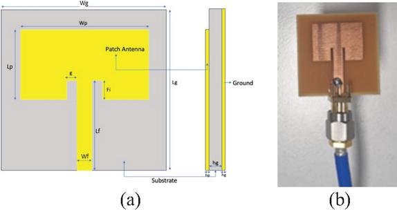
Figure 1 Configuration of (a) front and side of designed RMSPA and (b) fabricated RMSPA.
The impact of different substrate materials on the performance of a MSPA was analyzed using FR4 Glass Epoxy (), Rogers DT5880 (), Rogers 4003C (), Teflon (), Arlon AD300A (), and Alumina () with thicknesses of 1.6 mm and 1.0 mm, as summarized in Table 1.
2.1 Simulation and results of the six substrates for rectangular MSPA
The simulation begins with FR4, followed by Rogers DT5880, Rogers RO4003C, Teflon, Arlon AD300A, and Alumina (99%). Each substrate is analyzed using the MSPA at a frequency of 5.8 GHz. The results of the simulation are presented in Fig. 2, which shows the parameters, while Fig. 3 displays the corresponding radiation patterns.
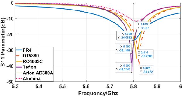
Figure 2 results of the six different substrates at 5.8 GHz.
The simulation results indicate that the Teflon substrate exhibits the lowest return loss of 44.2 dB among the six designs evaluated. This suggests that Teflon is the optimal material for researchers aiming to minimize return loss in their antenna projects.
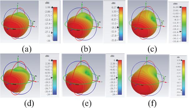
Figure 3 Radiation pattern of MSPA.
Radiation patterns demonstrate that Fig. 3 (a) FR4 and Fig. 3 (d) Teflon produce wider beams with lower gain, while Fig. 3 (b) Rogers and Fig. 3 (e) Arlon provide higher gain and more directional patterns. Figure 3 (f) Alumina creates a narrow beam, but with moderate gain. Material choice impacts gain, beamwidth, and side lobes. High-frequency laminates generally yield better radiation characteristics.
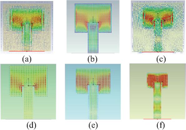
Figure 4 Surface current of RMSPA.
Figure 4 (a) FR4 and Fig. 4 (c) RO4003C exhibit more scattered currents, indicating higher losses. Figure 4 (b) Rogers and Fig. 4 (e) Arlon have concentrated on currents along the patch edges, improving efficiency. Figure 4 (d) Teflon shows moderate distribution, while Fig. 4 (f) Alumina has strong edge currents but limited spread. Material choice affects current flow, efficiency, and radiation behavior.
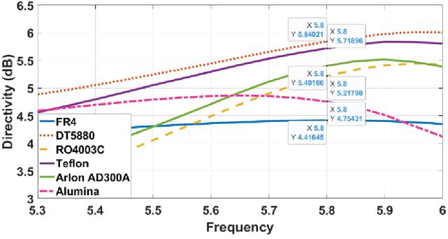
Figure 5 Directivity of the six different substrates comparison at 5.8 GHz.
Table 2 Dimensions of the MSPA and substrates at 5.8 GHz
| Results | ||||||
| Parameters | FR4 | DT5880 | RO4003 | Teflon | Arlon AD300A | Alumina (%99.5) |
| Bandwidth | 0.22 | 0.11 | 0.12 | 0.10 | 0.10 | 0.055 |
| Return Loss (dB) | -24 | -39 | -35 | -44 | -32 | -11 |
| Gain (dBi) | 1.98 | 6.17 | 6.24 | 5.99 | 6.09 | 6.17 |
| VSWR | 1.13 | 1.02 | 1.03 | 1.01 | 1.05 | 1.70 |
| Directivity (db) | 6.4 | 7.66 | 7.19 | 7.5 | 7.34 | 6.78 |
Higher-directivity substrates are typically lowloss, stable laminates (e.g., Rogers family), which better confine radiation. In comparison of six different substrates, the Rogers DT5880 substrate demonstrates the highest directivity, making it an excellent choice for applications where focused signal transmission is critical. Also, as illustrated in Fig. 5, for narrow beams at 5.8 GHz, DT5880/RO4003C are preferable to FR4/Arlon.
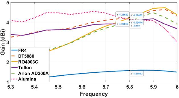
Figure 6 Gain of the six different substrates comparison at 5.8 GHz.
Rogers 4003C exhibits the highest gain, as shown in Fig. 6, of 6.244 dBi at 5.8 GHz. In contrast, FR4 shows the lowest gain among the six substrates analyzed, with a value of 1.989 dBi. This difference in performance can be attributed to the gain equation, which indicates that gain is influenced by both efficiency and directivity.
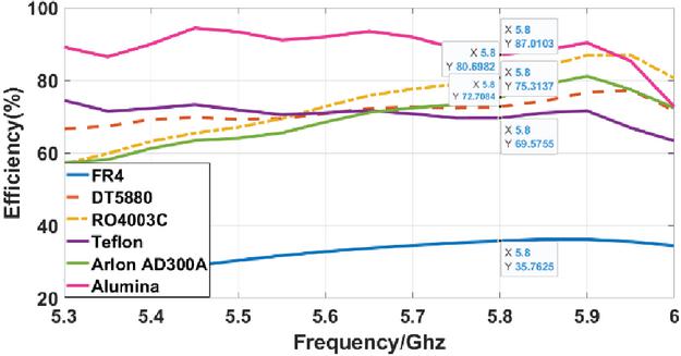
Figure 7 Efficiency of the six different substrates comparison at 5.8 GHz.
At 5.8 GHz, Alumina shows the highest efficiency (87%), followed by DT5880 (80%). RO4003C and Teflon are mid-tier (75% and 73%), while Arlon AD300A is slightly lower (70%). FR4 remains the least efficient (36%) due to higher dielectric and conductor losses, as illustrated in Fig. 7. Overall, low-loss, high-quality laminates deliver markedly better radiation efficiency than FR4, as summarized in Table 2.
2.2 Experimental analysis and results
After the simulations, measurements were first performed using a vector network analyzer (VNA) on a rectangular patch antenna fabricated on an FR4 substrate. Furthermore, a CMSPA operating at 5.8 GHz was designed, simulated, and fabricated on the same substrate, and its performance was subsequently measured using the VNA. The goal was to compare the impact of antenna shape on performance at the same frequency. This approach helps determine the optimal geometry and substrate for the desired application.
2.3 Analysis of the fabricated rectangular microstrip patch antenna
Substrate thickness from 1.6 mm to 1 mm has been varied to evaluate its influence on the MSPA parameters. All other dimensions of the antenna remained constant. FR4, which exhibited the lowest reflection coefficient for the proposed antenna, was selected for fabrication and measurement since it is readily available and offers a cost-effective manufacturing process.
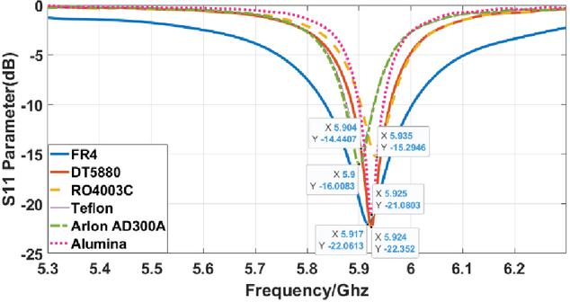
Figure 8 Reflection coefficient () of the FR4 with thickness of 1 mm substrate on CST Microwave Studio.
The S11 plot, as shown in Fig. 8, presents a comparison of return loss for six different substrates at a thickness of 1 mm. All antennas exhibit resonance near 5.8 GHz; however, DT5880 and RO4003C achieve the deepest nulls ( dB), indicating excellent impedance matching. Teflon, Arlon, and Alumina show slightly higher dB), still acceptable. FR4 performs worst ( dB) with a broader dip, suggesting higher mismatch and losses. Overall, lowloss laminates provide superior matching and bandwidth compared to FR4, as shown in Fig. 9.
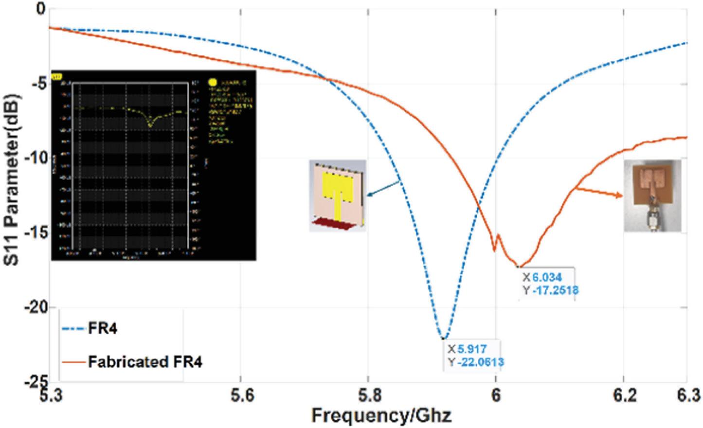
Figure 9 Comparison between simulated and fabricated results of the return loss of RMSPA.
The simulated antenna achieves its best performance at around 5.918 GHz with an of approximately 22.88 dB, whereas the fabricated antenna resonates near 6.003 GHz with an of about 14.08 dB, as summarized in Table 3. There is a noticeable frequency shift and reduced return loss in the fabricated design compared to the simulation. This variation can be attributed to fabrication tolerances and inconsistencies in material properties
Table 3 Comparison of fabricated and simulated rectangular MSPA
| Substrates | ||
| Parameters | FR4 | Fabricated FR4 |
| Frequency (GHz) | 5.919 | 6.034 |
| Bandwidth (GHz) | 0.168 | 0.24 |
| Return Loss (dB) | -22.109 | -17.251 |
| VSWR | 1.097 | 1.318 |
2.4 Simulation and results of the six substrates for CMSPA
A circular patch antenna, which is also frequently utilized in antenna design, was selected for further design and analysis. The dimensions of the circular patch antenna, substrate, feedline, gap, ground, and feed width are calculated using MATLAB code to determine the parameters of the MSPA, as illustrated in Fig. 10 [5].
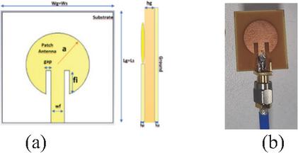
Figure 10 Configuration of (a) CMSPA front and side view (b) fabricated CMSPA.
The materials evaluated in this section are the same as those used for the rectangular MSPA, including FR4, Rogers DT5880, Rogers RO4003C, Teflon, Arlon AD300A, and Alumina (99%).
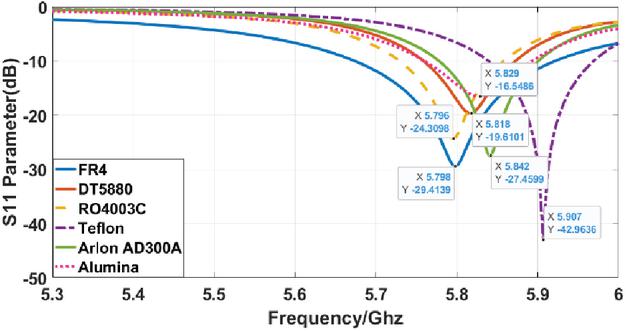
Figure 11 Results of the return loss () of six different substrates with 1.6 mm thickness.
Based on the results of the simulation of the circular patch antenna, the Teflon substrate has the lowest return loss value of , which is 42.96 dB at 5.9 GHz among the six designs, as evidenced in Fig. 11. As mentioned for the rectangular patch antenna, related results were obtained; however, the reflective frequency is 5.9 GHz, not 5.8 GHz. Therefore, we can conclude that FR4 had the lowest return loss at 5.8 GHz. Additionally, in terms of bandwidth performance, the operating frequency ranges from 5.67 GHz to 5.94 GHz, providing the largest bandwidth compared to the other substrates. Researchers can utilize Teflon as the optimal material for minimizing return loss at 5.9 GHz in their projects. However, for 5.8 GHz circular antennas, researchers can choose FR4 for their projects.
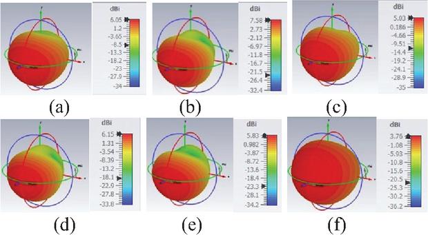
Figure 12 Radiation pattern of CMSPA.
The color scale indicates gain in dBi, where red regions correspond to higher gain and blue regions to lower gain. Figure 12 (a) FR4 and similar low-cost substrates exhibit broader lobes with moderate gain, while high-frequency laminates and Fig. 12 (f) Alumina shows more directional patterns and slightly higher peak gains. These variations highlight the impact of substrate dielectric properties on antenna radiation behavior.
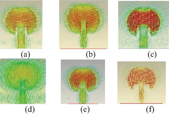
Figure 13 Surface current of CMSPA.
Figure 13 illustrates the surface current distribution of a circular patch antenna for six different substrates. The color scale represents current intensity in dB, where red indicates higher current concentration and blue indicates lower levels. Figure 13 (a) FR4 and similar substrates show relatively uniform current spread, while high-frequency laminates and Fig. 13 (f) Alumina exhibit more concentrated currents near the patch edges and feedline. These variations demonstrate how substrate dielectric properties influence current flow and antenna performance.
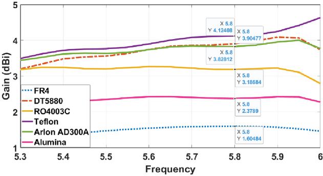
Figure 14 Gain of the six different substrates comparison at 5.8 GHz.
Alumina shows the highest gain, reaching about 4.24 dB near 5.8 GHz, followed by Arlon AD300A and RO4003C with gains around 3.9–4.0 dBi. Rogers DT5880 and Teflon exhibit moderate gains between 2.5–3.5 dBi, while FR4 has the lowest gain, staying below 2 dBi throughout the band. As shown in Fig. 14, the trend indicates that high-frequency laminates and ceramic substrates significantly improve antenna gain compared to low-cost FR4. This highlights the importance of substrate selection for optimizing antenna performance.
2.5 Analysis of the fabricated circular microstrip patch antenna
After analyzing the CMSPA simulation in CST Microwave Studio, the fabricated CMSPA can be compared with the simulated design.
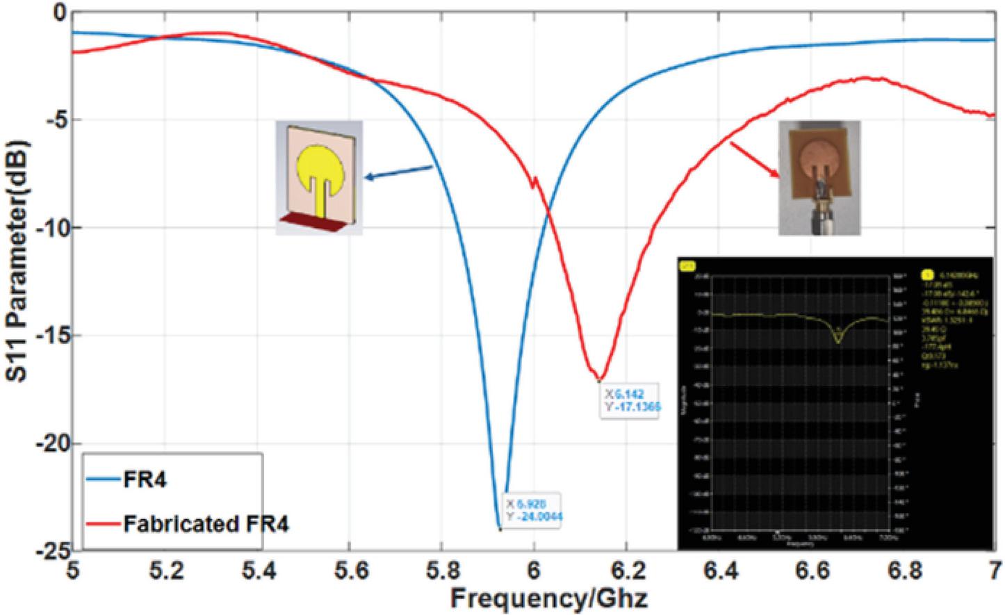
Figure 15 Comparison between simulated and fabricated results of the return loss () of CMSPA.
In Fig. 15, the blue dashed line represents the simulation, showing a deep resonance at 5.928 GHz with an of about 24 dB. The fabricated antenna (red line) resonates at 6.142 GHz with an of approximately 17.09 dB, indicating a frequency shift and reduced return loss compared to the simulation. This discrepancy is likely due to fabrication tolerances, connector effects, and material property variations. Overall, the antenna maintains acceptable performance despite these differences.
For both RMSPA and CMSPA, the same measurement techniques and conditions were used. We also observe similar discrepancies between the measured and simulated results depicted in the graph. However, these two different shapes of the MSPA are suitable for sub-6 GHz devices and applications. In Fig. 15, the results from the fabricated antenna closely align with the simulated results. One potential reason for the shift in the resonance frequency to a higher range could be attributed to the soldering effect of the SMA connector.
Table 4 Comparison of fabricated and simulated CMSPA
| Substrates | ||
| Parameters | FR4 | Fabricated FR4 |
| Frequency (GHz) | 5.928 | 6.142 |
| Bandwidth (GHz) | 0.186 | 0.282 |
| Return Loss (dB) | -24 | -17.09 |
| VSWR | 1.134 | 1.325 |
During the analysis of the fabricated CMSPA assembled on an FR4 substrate, the bandwidth is larger than the simulated one, as presented in Table 4. However, the return loss of the fabricated antenna has decreased by approximately 0.857 dB due to the measurement process. This discrepancy can be attributed to the manufacturing process or limitations of the measurement method. These small errors in the fabricated antenna can contribute to shifts in the results. Based on the VSWR value, we can conclude that there is minimal distortion in the standing wave. Furthermore, when comparing the fabricated antenna with the simulation, both the return loss and VSWR results indicate that the simulated antenna performs better than the fabricated one. However, these differences do not mean that we cannot use the fabricated antenna. On the contrary, we can use the fabricated antenna for our applications and devices that operate sub-6 GHz.
3 CONCLUSION
This study investigates the design and performance of microstrip patch antennas (MSPAs) using six different substrates (FR4 Glass Epoxy, Rogers DT5880, Rogers 4003C, Teflon, Arlon AD300A, and Alumina) through simulations in CST Microwave Studio. Both rectangular and CMSPAs’ configurations were analyzed, with copper patches and ground planes. Simulation results revealed substrate-dependent performance variations: RMSPA achieved a maximum gain of 6.244 dBi with Rogers 4003C, while FR4 provided the widest bandwidth (0.229 GHz). Rogers DT5880 exhibited the highest directivity (7.665 dB), Teflon delivered the best return-loss (44.20 dB), and Alumina demonstrated superior efficiency. To experimentally validate the simulation results, FR4based antenna prototypes with a substrate thickness of 1 mm were fabricated and characterized using a VNA. In the simulation stage, both 1 mm and 1.6 mm substrate thicknesses were considered to analyze the impact of substrate thickness on antenna performance. Measurements indicated a resonance frequency shift and reduced return loss, primarily due to manufacturing tolerances and SMA connector soldering effects. The findings highlight the significant influence of dielectric constant, substrate thickness, and fabrication conditions on MSPA performance, providing practical design guidelines for sub-6 GHz wireless communication systems.
ACKNOWLEDGEMENT
The authors used AI tools (Microsoft M365 Copilot) for grammar corrections and improvements in phrasing.
REFERENCES
[1] P. S. Hall, J. R. James, and C. Wood, “Microstrip antenna theory and design,” IEE Peter Peregrinus, p. 204, 1981.
[2] H. Gutton and G. Baissinot, European Patent 0 007 222, 9 July 79 https://patentimages.storage.googleapis.com/fc/02/c8/f213687a95df2e/EP0007222A1.pdf
[3] C. A. Balanis, Antenna Theory: Analysis and Design. Hoboken, NJ, USA: John Wiley & Sons, 2016.
[4] D. M. Pozar, Microwave Engineering: Theory and Techniques. Hoboken, NJ, USA: John Wiley & Sons, 2021.
[5] T. Samaras, A. Kouloglou, and J. N. Sahalos, “A note on the impedance variation with feed position of a rectangular microstrip-patch antenna,” IEEE Antennas and Propagation Magazine, vol. 46, no. 2, pp. 90–92, 2004.
[6] B. Tütüncü, “Microstrip antenna for 5G communication: Design and performance analysis,” in 2020 International Congress on Human-Computer Interaction, Optimization and Robotic Applications (HORA), IEEE, 2020.
[7] A. Khan and R. Nema, “Analysis of five different dielectric substrates on microstrip patch antenna,” International Journal of Computer Applications, vol. 55, no. 14, 2012.
[8] A. Ibrahim, E. Tetik, and S. Karamzadeh, “A wearable circularly polarized antenna for 5G applications,” in 2022 30th Signal Processing and Communications Applications Conference, IEEE, 2022.
[9] A. Kashkool, S. Yahya, H. Al-Rizzo, A. Al-Wahhamy, and A. A. Issac, “On the design and simulation of antennas on ultra-thin flexible substrates,” Applied Computational Electromagnetics Society (ACES) Journal, vol. 33, no. 7, pp. 798–801, July 2018.
[10] R. Gonçalves, R. Magueta, P. Pinho, and N. B. Carvalho, “Dissipation factor and permittivity estimation of dielectric substrates using a single microstrip line measurement,” Applied Computational Electromagnetics Society (ACES) Journal, vol. 31, no. 2, pp. 118–125, Feb. 2016.
[11] S. Karamzadeh and V. Rafiei, “Circularly polarized MTS based antenna design for C Band applications,” in 2020 28th Signal Processing and Communications Applications Conference (SIU), IEEE, 2020.
[12] F. Göksel and S. Karamzadeh, “Comparison of six different dielectric substrates in microstrip patch antenna design,” in 2024 32nd Signal Processing and Communications Applications Conference (SIU), IEEE, 2024.
[13] F. Göksel and S. Karamzadeh, “Evaluating substrate influence on rectangular and circular microstrip patch antennas for 5G,” in 2024 IEEE Workshop on Microwave Theory and Technology in Wireless Communications (MTTW), 2024.
BIOGRAPHIES

Fatih Göksel received his B.S. degree in Electrical and Electronics Engineering from the Turkish Military Academy, Türkiye, in 2006. He completed his M.S. degree in Electrical and Electronics Engineering at Kıurklareli University in 2018, where his research focused on Frequency Selective Surfaces (FSS) and their applications in electromagnetic systems. He is currently pursuing his Ph.D. degree at the Electrical and Electronics Engineering Department of Bahçeşehir University, İstanbul, and is expecting to graduate in 2026. His doctoral research focuses on microstrip patch antennas, metamaterial-based structures, Fabry-Perot cavity antennas, and gain enhancement techniques for 5G and emerging 6G communication systems. Between 2006 and 2022, he served as a Communication Officer in the Turkish Armed Forces (TAF), gaining extensive experience in military communication systems, RF technologies, and field operations. In 2020, he worked within a NATO international assignment for one year, contributing to multinational communication and coordination activities. Following his military career, he worked between 2022 and 2025 as a Resident Engineer at Motherson Group, where he was actively involved in global automotive engineering projects, supplier management, and technical coordination. He is currently working at Mercedes-Benz Türk (Daimler Truck) as a Supplier Manager at the Aksaray Truck Plant in Türkiye, focusing on supplier development, technical validation, and industrial quality processes. Göksel has contributed to the scientific community through peer-reviewed conference publications in the field of antenna design and wireless communications. His recent works include substrate optimization, antenna geometry comparison, and performance enhancement for sub-6 GHz and 5G applications, contributing to the advancement of compact and efficient antenna systems.

Saeid Karamzadeh (IEEESM) received his M.S. and Ph.D. degrees in Communication Systems from Istanbul Technical University, Türkiye, in 2013 and 2015, respectively. His Ph.D. thesis, Circularly Polarized Array Antenna Design for C-Band Applications, earned him the Most Successful Ph.D. Thesis Award from the Istanbul Technical University Rectorate. Karamzadeh is currently a Senior Scientist with the Millimeter Wave Technologies Unit, Intelligent Wireless Systems Division at Silicon Austria Labs, Linz, Austria, where he leads research and development in mm-wave communication systems, CubeSat antennas, reconfigurable intelligent surfaces, and radar technologies. He has secured funding for several high-impact projects from diverse sources, including the European Space Agency (ESA), national and international research grants, and industrial partnerships. His work has included collaborations with leading companies on innovative radar systems, automotive, and communication technologies. Alongside his role at Silicon Austria Labs, Karamzadeh is a full professor in the Electrical and Electronics Engineering Department, Faculty of Engineering and Natural Sciences at Bahçeşehir University, Istanbul, Türkiye. He teaches courses on antenna theory, microwave systems, and communication technologies. His research interests include antenna design, mm-wave systems, wearable and flexible antennas, and radar applications for healthcare and automotive industries. He has supervised several doctoral and master’s students and led research initiatives in partnership with academic institutions and industry leaders. Throughout his career, Karamzadeh has contributed significantly to the scientific community with over 100 peer-reviewed journal articles and conference papers. His research has appeared in highly regarded journals such as IEEE Microwave and Wireless Components Letters, IEEE Journal of Microwaves, IEEE Access, Electronics Letters, and Physica Scripta. His work on microwave, antenna design, and metamaterials has garnered significant recognition, including top-downloaded paper awards, best paper interviews, and best paper honors at major IEEE conferences. Karamzadeh is an active member of the IEEE, serving as a senior member since 2024. He has been an invited speaker at numerous international conferences and workshops and has chaired sessions on metamaterials and intelligent surfaces. In addition, he regularly reviews papers for major IEEE journals, including IEEE Transactions on Microwave Theory and Techniques and IEEE Antennas and Wireless Propagation Letters. Complementing his academic work, Karamzadeh was the founder of GraphenePi R&D Engineering (2018–2024), a startup company specializing in innovative antenna designs, RF systems, and custom solutions for communication technologies. Under his leadership, the company successfully completed numerous R&D projects and collaborated with industry leaders on breakthrough communication technologies. His research interests span advanced antenna design, mm-wave and subterahertz communication systems, radar technologies, and metasurface-based design.
ACES JOURNAL, Vol. 41, No. 5, 431–439
DOI: 10.13052/2026.ACES.J.410505
© 2026 River Publishers