Design and Electromagnetic Analysis of Stator-Modular Tubular Linear Rotary Machine
Hao Chen1, 2, 3, 4*, Cheng Liu1, Marcin Wardach5, Javokhir Toshov6, Xing Wang2, 3*, Ali Asghar Memon7, Bodrenkov Evgenii Alexandrovich8, Popov Stanislav Olegovich8, Nikolay Korovkin8, Sakhno Liudmila8, Emmanuel Karapidakis9, Aris Dimeas10, Sherif Moussa11, and Habes Ali Khawaldeh12
1School of Electrical Engineering China University of Mining and Technology, Xuzhou 221116, China
hchen@cumt.edu.cn, Chengliu97@cumt.edu.cn
2Shenzhen Research Institute China University of Mining and Technology, Shenzhen 515100, China
3512@cumt.edu.cn
3Jiangsu Province Foreign Expert Workshop on New Energy Power Generation and Electric Transportation Xuzhou 221008, China
4International Joint Research Center of Central and Eastern European Countries on New Energy Electric Vehicle Technology and Equipment Xuzhou 221008, China
5Department of Electrical Machines and Drives West Pomeranian University of Technology, Sikorskiego 37, 70-313 Szczecin, Poland
6Tashkent State Technical University University Street No2, 100095 Tashkent, Uzbekistan
7Mehran University of Engineering and Technology Department of Electrical Engineering, Jamshoro, Pakistan
8The Institute of Energy Peter the Great Saint Petersburg Polytechnic University, Saint Petersburg, Russia
9School of Engineering Hellenic Mediterranean University, Estavromenos Campus,71004 Heraklio, Crete, Greece
10Athens National University of Technology Greece
11School of Engineering Canadian University Dubai, 117781, Sheikh Zayed Road, Dubai, United Arab Emirates
12The Renewable Energy Engineering Department Faculty of Engineering, Al al-Bayt University, Mafraq, Jordan
*Corresponding author
Submitted On: January 16, 2026
Accepted On: June 12, 2026
ABSTRACT
This paper proposes a novel modular stator 6-pole tubular linear rotary switch reluctance machine (TLRSRM). The proposed structure employs circumferentially distributed H-shaped stator modules, with each module’s four poles wound with concentrated windings. The outer stator pole windings and outer rotor form a three-phase radial magnetic circuit driving rotational motion, while the inner stator pole windings and inner rotor constitute a single-phase transverse magnetic circuit driving linear motion. This paper elucidates the motor’s operating principle and electromagnetic design process. Based on the three-dimensional magnetic field distribution characteristics, finite element analysis (FEA) was employed for three-dimensional magnetic field calculations to obtain flux linkage and torque characteristics. Additionally, the electromagnetic coupling effects between rotational and linear motions were investigated for the conjugate rotary-linear magnetic circuit within the modular stator. Simulation results indicate minimal electromagnetic coupling effects in the proposed TLRSRM structure. This study provides a robust theoretical foundation and empirical data support for further optimization and practical application of this motor topology.
Keywords: 3D finite element model, magnetic field distribution, static electromagnetic characteristics, switched reluctance machine..
1 INTRODUCTION
With the advancement of industrial automation and the growing utilization of integrated ocean energy systems (e.g., hybrid offshore wind and wave energy conversion), there is an increasing demand for drive systems with enhanced functional integration and multi-axis motion control capabilities. Conventional single-degree-of-freedom electric motors exhibit inherent constraints, including limited operational flexibility, cumbersome mechanical arrangements, and suboptimal spatial efficiency, which restrict their applicability in sophisticated working environments. In response to these challenges, multi-degree-of-freedom motor architectures have gained prominence as a cutting-edge research domain, characterized by their compact modular construction, multifunctional operation, and adaptable kinematic control. Among various machine types, the switched reluctance motor (SRM) has become a potential choice for multi-degree-of-freedom drive applications, owing to its mechanical simplicity, operational ruggedness, and reliable performance under demanding conditions [1, 2, 3, 4].
The two-degree-of-freedom linear-rotary SRM represents an emerging motor category with promising practical implications. This configuration achieves synchronized rotational and translational movements within a unified electromagnetic structure, thereby creating new possibilities for advanced applications requiring complex motion patterns, such as precision industrial automation and marine power generation equipment. Nevertheless, current research efforts continue to concentrate predominantly on performance refinement of conventional single-degree-of-freedom reluctance machines. Investigations into two-degree-of-freedom linear-rotary variants remain at an early developmental stage, with fundamental aspects including topological synthesis and electromagnetic interaction mechanisms necessitating further systematic investigation and theoretical consolidation [5, 6, 7].
Two-degree-of-freedom motors can be categorized into coaxial and non-coaxial structural types based on the relationship between their rotational and linear motion axes. Regarding coaxial configurations, [8, 9, 10] report a structurally simplified rotary-linear SRM. Its distinctive feature lies in simultaneously achieving rotational motion and axial displacement via a single shaft, offering a novel drive solution for advanced automotive applications with stringent spatial constraints. Reference [11] proposes a rotating linear switched reluctance motor (RLSRM) specifically designed for gear engagement/disengagement control. This innovative design integrates a three-phase 6/4 rotary reluctance unit with a two-phase transverse flux linear reluctance unit. Experimental studies validate its operational performance and engineering applicability. Reference [12] further developed a three-phase modular linear-rotary switched reluctance motor (MLRSRM) for electromagnetic launch applications. Its segmented stator-rotor design not only reduces motor mass but also optimizes magnetic circuit efficiency, significantly enhancing torque density through improved material utilization. Finite element simulation systems evaluated the device’s static and dynamic characteristics.
Regarding non-coaxial structures, [13] developed a dual-degree-of-freedom SRM with decoupled rotational and linear motion mechanisms. Its innovation lies in employing a disc-type dual-rotor 12-slot 10-pole structure for rotational motion, while an external tubular magnetic ring assembly achieves linear drive. Both winding systems can be independently controlled. Addressing the application requirements of wave-wind combined power generation systems (WWCPGS), [14] proposes a linear-rotary permanent magnet generator (LRPMG). Key electromagnetic parameters, including three-phase counter-EMF, output voltage, air gap magnetic flux density distribution, and external characteristics, are systematically analyzed using finite element methods.
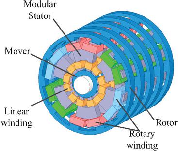
Figure 2 Multi-angle views of TLRSRM: (a) cross-sectional split diagram, (b) movers assembly drawing, and (c) side view of ferromagnetic ring arrangement.
Although existing research has developed various configurations of two-degree-of-freedom motors and validated their feasibility in achieving composite motion functions through electromagnetic simulation and experimentation, such motors face inherent structural limitations despite their performance advantages. Compared to traditional single-degree-of-freedom motors, two-degree-of-freedom structures capable of simultaneously outputting rotational and linear motion often suffer from configuration redundancy due to increased mechanical complexity. This redundancy leads to higher iron core material consumption, consequently increasing the overall mass and volume of moving components.
Based on the research in [12, 13], this paper innovatively proposes a linear-rotary SRM employing a modular stator design. This structure effectively reduces the overall motor weight through the modular integration of stator units, thereby significantly enhancing the system’s power density.
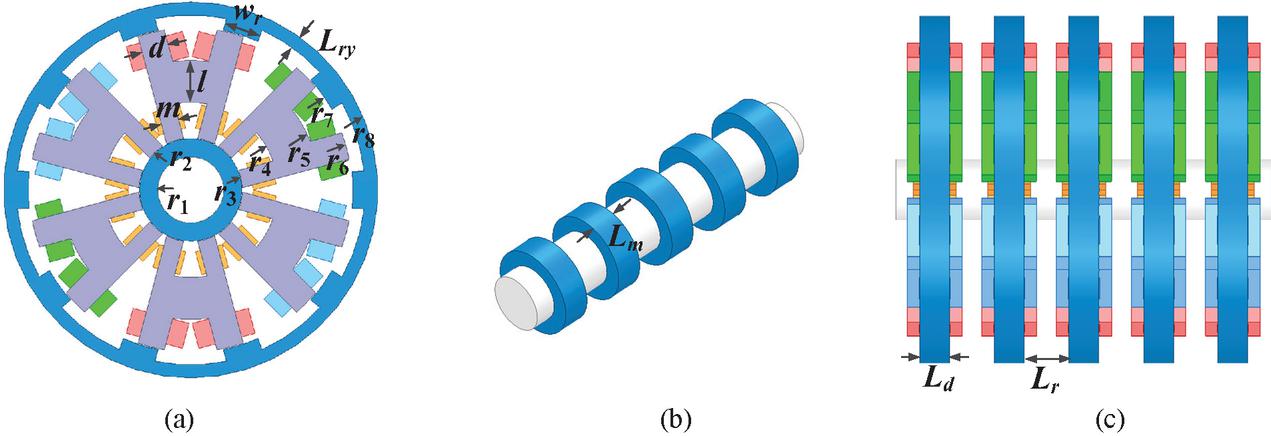
Figure 1 3-D views of proposed TLRSRM model.
2 STRUCTURE AND OPERATING PRINCIPLE OF TLRSRM
Building upon existing research and addressing the application requirements of two-degree-of-freedom composite motion motors, this paper proposes a novel modular stator 6-pole cylindrical linear rotary switch reluctance motor (TLRSRM). This TLRSRM inherits the typical characteristics of SRMs, with its cross-sectional structure closely resembling that of traditional rotary SRMs. The rotor is assembled within the space enclosed by stator modules, maintaining an air gap with the stator. Both the stator and rotor magnetic paths are constructed by stacking 50DW470 silicon steel sheets with excellent magnetic permeability. Figure 1 displays the 3D model of the TLRSRM. Figure 2 presents views of the TLRSRM from different angles. Figure 2 (a) shows a cross-sectional view of the TLRSRM, Fig. 2 (b) depicts the rotor structure, and Fig. 2 (c) illustrates the side view of the ferromagnetic ring arrangement. The stator of the TLRSRM comprises six H-shaped modular units. Each H-shaped unit features four magnetic poles, with windings wrapped around each pole. Windings on adjacent poles exhibit opposite polarity. In the symmetrical pair of H-shaped stator modules, windings on the two pole teeth facing away from the axis are connected in series. This configuration forms one phase of the three-phase rotating winding, driving rotational motion. The windings on the two pole teeth facing the axis in all H-type module stators are connected to form one phase for single-phase linear drive. As a single-phase configuration, its feeding mechanism does not involve multi-phase commutation. Instead, it relies on a single-channel pulsed direct current (DC) excitation. This excitation is strictly synchronized with the real-time axial position of the mover rings to maximize the electromagnetic pull towards the alignment position. The rotor of the TLRSRM consists of a non-magnetic central shaft and ferromagnetic rings uniformly mounted at specific intervals around the central shaft. Specifically, the axial spacing distance between adjacent ferromagnetic rings (denoted as ) is designed to be 25 mm, as listed in Table 1. This specific interval is a critical structural parameter, as it dictates the periodic variation of the transverse magnetic reluctance and directly governs the generation and magnitude of the axial thrust force. This rotor design features a simple structure, facilitates easy assembly, and is straightforward to manufacture. The non-magnetic central shaft, which provides structural support, can be fabricated from aluminum, contributing to reduced overall weight and lower production costs. This phase-splitting design enables the motor to independently control rotational and linear motion, achieving a dual-axis output structure where the inner rotor handles linear displacement and the outer rotor performs rotational motion. The proposed TLRSRM features quadrant operation capability, functioning both in electric drive mode and power generation mode. It holds broad application prospects in fields requiring composite motion control, such as industrial smart manufacturing equipment and ocean energy power generation systems.
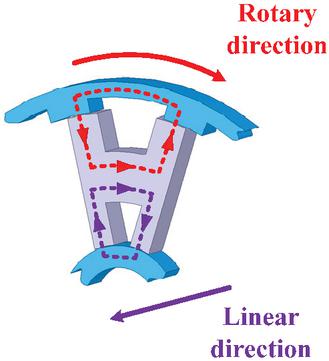
Figure 3 Schematic diagram of magnetic circuit flow path.
As illustrated in the structural breakdown in Fig. 2, the proposed TLRSRM utilizes an H-shaped stator module where the outer poles govern rotary motion and the inner poles are dedicated to linear motion. Figure 3 further elucidates the three-dimensional magnetic flux flow paths within a single H-type stator unit. In the rotational motion mode, the magnetic flux generated by the outer rotary windings flows radially and forms a closed loop circumferentially through the outer rotor and the stator yoke. This radially configured annular magnetic circuit generates a tangential electromagnetic force in the air gap, driving the outer rotor components to rotate.
Conversely, the generation of axial thrust force relies on a distinctly different transverse flux mechanism. As depicted by the flow paths in the inner section of Fig. 3, when the inner linear windings are excited, the magnetic flux travels radially through the inner H-stator poles and then closes its path axially through the stator yoke and the inner rotor. Crucially, as shown in Figs. 2 (b) and (c), the inner rotor consists of discrete ferromagnetic rings separated by non-magnetic spaces along the axial direction. Driven by the principle of minimum magnetic reluctance, this transverse flux distribution within the inner stator-rotor air gap generates a strong axially acting electromagnetic force. This thrust force pulls the nearest inner rotor ferromagnetic rings into alignment with the excited stator poles, thereby propelling the central shaft in a linear displacement.
The H-shaped stator-modular design employed in the TLRSRM enables the magnetic flux to form a closed circuit along a more compact path during motor operation. This structural feature not only effectively reduces the total magnetic resistance of the magnetic circuit but also significantly enhances the utilization efficiency of the core material. The combined effects of shortened magnetic circuit length and reduced magnetic resistance effectively improve the motor’s torque output capability and power density.
Furthermore, to accommodate continuous rotational motion exceeding (such as in wind energy conversion applications), the mechanical connection between the inner and outer moving components, as well as the layout of the stator conductors, requires specific engineering considerations. In practical implementation, the inner central shaft and the outer rotor are mechanically coupled via a rigid connecting flange on one side of the machine. Consequently, the modular stator is supported by a stationary cantilever structure from the opposite side. This single-sided support configuration ensures that the coupled movers can rotate freely without interfering with the stator supports. Crucially, the stationary cantilever support provides a dedicated hollow pathway for safely routing the power conductors to the inner and outer stator windings. To ensure the mechanical robustness of this cantilevered construction under operational vibrations and radial magnetic pulls, high-strength structural materials and heavy-duty precision bearings must be employed at the single-sided support end.
3 DESIGN PROCESS OF TLRSRM
The design process for the novel TLRSRM proposed in this paper is illustrated in Fig. 4. Considering that rotational and linear motion follow similar electromagnetic principles, this study establishes a corresponding mathematical model using rotational motion as an example. Based on the law of conservation of energy and Faraday’s law of electromagnetic induction, the terminal voltage across each stator phase winding can be described by the combined effects of resistance voltage drop and the induced electromotive force generated by magnetic flux variation. Accordingly, the terminal voltage equation for the th phase winding of the motor can be expressed as [12]:
| (1) |
where is winding voltage, and represent the winding current and magnetic flux generated in the th phase winding of the generator, respectively, and is the stator resistance.
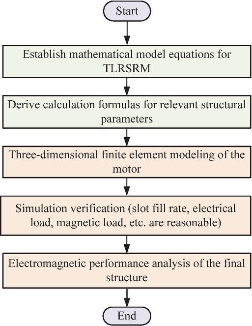
Figure 4 Design flowchart for the new TLRSRM structure.
Due to the double-convex pole structure of the SRM, when a large excitation current is applied, the core saturation causes its electromagnetic characteristics to exhibit nonlinearity. Magnetic flux and inductance are functions of both current and rotor position. Magnetic flux can be calculated as the product of the winding inductance and current, as shown in Equation (2)
| (2) |
where is the position of the rotor and is the winding inductance of the th phase.
When the stator and rotor are aligned, the expression for the single-phase flux linkage is
| (3) |
where is inductance at the alignment position, is the average magnetic density of the surface of the stator pole section at the aligned position, initially assumed to be is the overlapping cross-sectional area of the stator and rotor poles, and is the number of windings turns per phase of the motor.
Integrating equation (2) results in the expression for the magnetic co-energy of the winding
| (4) |
By performing the partial derivative of magnetic co-energy at any operating position , the electromagnetic torque of the motor can be obtained. Its calculation equation is [13]
| (5) |
Similarly, the generation of axial thrust force is governed by the tendency of the single-phase transverse magnetic circuit to minimize its reluctance. When the linear windings are excited, an axially acting electromagnetic force is produced to align the inner rotor ferromagnetic rings with the inner stator poles. The axial thrust force can be calculated by taking the partial derivative of the magnetic co-energy with respect to the linear displacement
| (6) |
Based on the established mathematical model of the motor system, the next step involves dimensional design of the motor’s primary structural parameters. The rotating section adopts an inner stator-outer rotor configuration, while the linear section’s structure closely resembles that of a rotary reluctance motor (RSRM) in cross-sectional height. Given the scarcity of literature on structural parameter design for transverse flux switch reluctance linear motors, the proposed motor’s structural parameters were determined by drawing upon design experience from RSRMs.
If the linear unit is not considered, according to the design theory of the rotary motor, the main size expression of the rotary unit is [14]
| (7) |
where is the outer radius of the stator, is the axial length of the stator, is the power of the rotary part, is the power factor, is the rotational speed, and the output coefficient represents the combined utilization level of the electric and magnetic loadings per unit stator volume in the main sizing equation. A larger value indicates higher material utilization and greater power density. Based on design experience from RSRMs, the typical recommended range of is 0.4 to . In this design, is selected according to the rated power and speed requirements.
The inner radius and outer radius of the H-type stator pole can be expressed by
| (8) |
where and represent the inner radius and outer radius of the H-type stator yoke, respectively, and denote proportional coefficients, typically ranging from 0.4 to 0.7 based on RSRM’s design experience. In this design, is selected to balance the slot fill factor and magnetic circuit length, is selected to ensure the yoke flux density remains within the saturation limit while maintaining sufficient winding space.
The equation for calculating the thickness of an H-type stator yoke satisfies
| (9) |
where and represent the widths of the upper and lower pole teeth of the H-type stator, respectively.
Additionally, when determining the values for the stator inner radius and rotor outer radius , it is important to note that excessively small values may result in insufficient mechanical strength of the motor. This could lead to fractures during operation, thereby reducing the motor’s service life. Therefore, mechanical strength must be considered when selecting these values. Simultaneously, while ensuring mechanical strength, the dimensions of the rotor yoke and stator yoke must be maintained to satisfy the requirements for magnetic circuit saturation.
Based on the theoretical derivation from equations (7)–(9) and drawing upon established design practices for conventional RSRMs, the initial values for key structural dimensions of the proposed TLRSRM can be preliminarily determined, as listed in Table 1.
Table 1 Structure parameters of the TLRSRM
| Item | Unit | Value |
| Mover inner radius/ | mm | 13 |
| Stator pole inner radius/ | mm | 16 |
| Stator yoke inner radius/ | mm | 26 |
| Stator yoke thickness/ | mm | 14 |
| Stator pole outer radius/ | mm | 50 |
| Rotary stator pole width/ | mm | 8.2 |
| Linear stator pole width/ | mm | 5.3 |
| Rotor outer radius/ | mm | 58 |
| Rotor pole width/ | mm | 11 |
| Rotor yoke thickness/ | mm | 4 |
| Mover ring length/ | mm | 10 |
| Stator ring length/ | mm | 10 |
| magnetic ring spacing width/ | mm | 25 |
| Stator-rotor air gap length | mm | 0.3 |
| Stator-mover air gap length | mm | 0.2 |
| Core axial length | mm | 110 |
4 3D FINITE ELEMENT CALCULATION OF TLRSRM
This study employed finite element analysis to simulate the electromagnetic performance of the designed TLRSRM. In the simulation calculations, eddy currents within the core causing magnetic field disturbances are not considered at this stage. For clarity, one phase of the rotary winding and the single-phase linear winding within a single ferromagnetic ring structure are selected as representative examples for analysis. By applying independent excitation to each phase winding, the magnetic field distributions of the stator, rotor, and mover are obtained at both aligned and misaligned positions (Figs. 5 and 6). Figure 5 (a) displays the three-dimensional mesh partitioning diagram of the TLRSRM in the finite element software, while Fig. 5 (b) presents the vector diagram of the three-dimensional magnetic flux paths. When the rotating rotor and linearly displacing stator are in misaligned and aligned positions, respectively, the TLRSRM exhibits four distinct positional states. Their magnetic flux density contour plots are displayed in Fig. 6. Simulation results indicate that, when the stator and rotor/mover are aligned, the maximum magnetic flux density within the stator core region occurs at the core edges where components meet the air gap, reaching approximately 1.8 T. The rated current for the rotating winding is 9 A, and the rated current for the straight winding is 6 A. Figures 5 and 6 show the magnetic flux density contour plots under rated operating conditions.
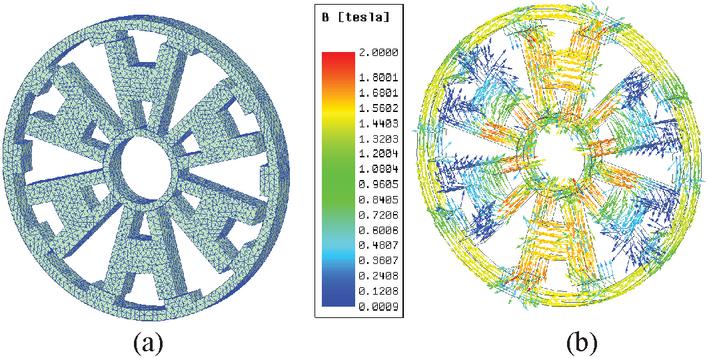
Figure 5 3D finite element model: (a) finite element mesh diagram and (b) magnetic flux density vector diagram.
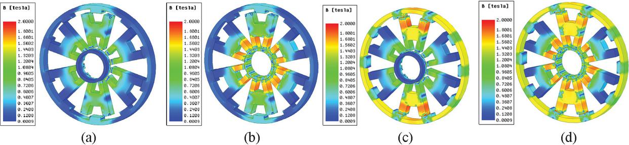
Figure 6 Magnetic flux density contour map: (a) rotor and mover at unaligned position, (b) rotor at unaligned position, and stator at aligned position, (c) rotor at aligned position, and stator at unaligned position, and (d) rotor and stator at aligned position.
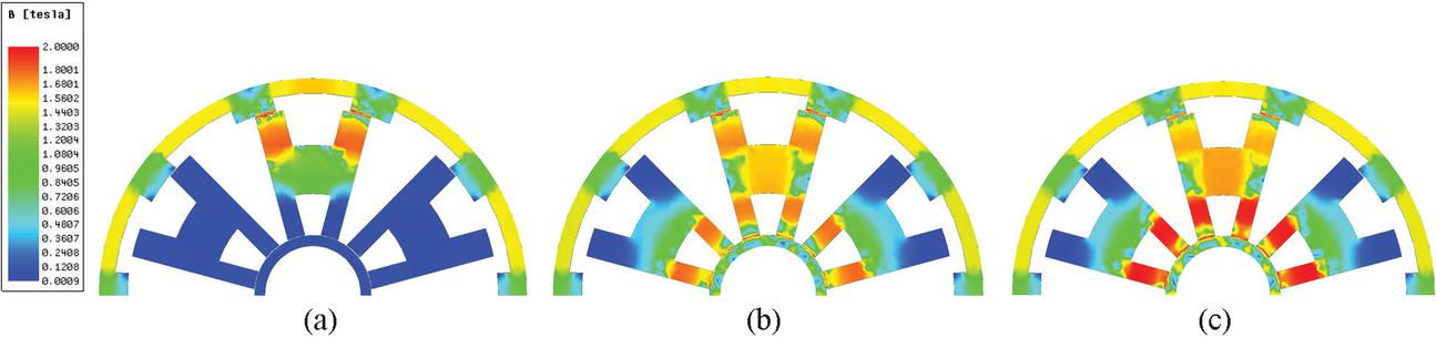
Figure 7 Magnetic flux density contour map under positive current excitation of different linear windings: (a) zero excitation, (b) rated excitation, and (c) double rated excitation.
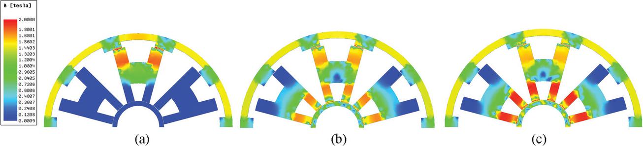
Figure 8 Magnetic flux density contour map under reverse current excitation of different linear windings: (a) zero excitation, (b) rated excitation, and (c) double rated excitation.
In the proposed TLRSRM structure, the rotary winding and linear winding are integrated within the same set of stator modules. As shown in Fig. 3, the magnetic paths generated by the two motion modes overlap at the stator yoke, inevitably inducing electromagnetic coupling effects. Therefore, to analyze the impact of this coupling effect, we examined the mutual influence between linear motion and rotary motion under different current directions and levels.
While maintaining the current of one phase of the rotary winding at its rated value, the excitation state and direction of the linear winding’s current were varied. Figures 7 and 8 display the magnetic flux density contour plots within the motor when the linear winding operates under zero excitation, rated excitation, and double overload excitation conditions.
It can be observed that in Fig. 7, the magnetic flux direction generated by the linear winding within the stator yoke is identical to that of the rotary winding. Consequently, the magnetic flux density in the stator yoke approaches saturation. In Fig. 8, the magnetic flux direction generated by the linear winding in the stator yoke is opposite to that of the rotating winding. Thus, the magnetic fluxes in the stator yoke cancel each other out, resulting in a low magnetic flux density.
Corresponding to these three operating states, Fig. 9 (a) presents the static torque waveform generated by rotational motion when the magnetic fluxes of the rotating and linear windings are in the same direction. Figure 9 (b) shows the static torque waveform when the magnetic flux directions of the rotating and linear windings are opposite. It can be observed that regardless of whether the linear winding current direction changes, or when the current magnitude varies from zero excitation to double excitation, the static torque waveform exhibits only minor changes. The variation rate of the static average torque value does not exceed 5%. This data indicates that the electromagnetic coupling effect is relatively small.
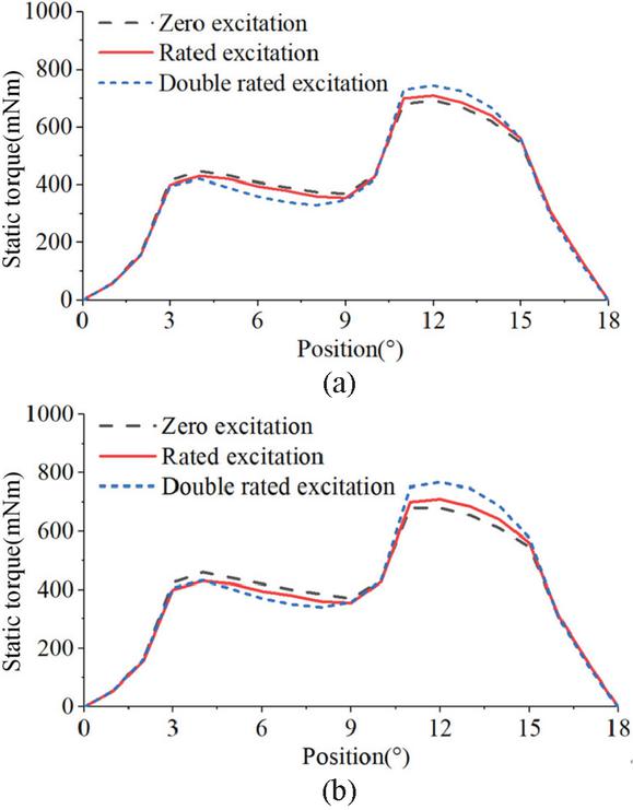
Figure 9 Static torque waveforms under different linear winding current excitation: (a) positive current and (b) reverse current.
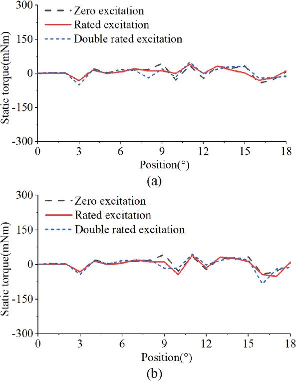
Figure 10 Radial force waveform under different linear winding current excitation: (a) positive current and (b) reverse current.
Additionally, Fig. 10 displays the dynamic response waveform of the radial force exerted by the linear winding excitation on the rotor during its movement from a misaligned position to an aligned position. Analysis reveals that throughout the entire motion process, the fluctuation amplitude of the radial force remains relatively limited, with its numerical variation consistently within acceptable engineering tolerance ranges. This phenomenon further confirms, from a mechanical characteristics perspective, that the TLRSRM topology proposed in this paper exhibits weak electromagnetic coupling effects between different motion modes and possesses excellent decoupling characteristics.
To further analyze the fundamental magnetic flux and torque characteristics of the proposed TLRSRM structure, the static characteristics as a function of current are presented for both rotational and linear motion modes. It should be noted that these baseline curves are evaluated under independent excitation conditions; that is, when analyzing the static characteristics of one motion mode, the supply current of the other motion mode is strictly held at zero. The magnetic flux curve is shown in Fig. 11, while the static torque and static thrust curves are depicted in Fig. 12.
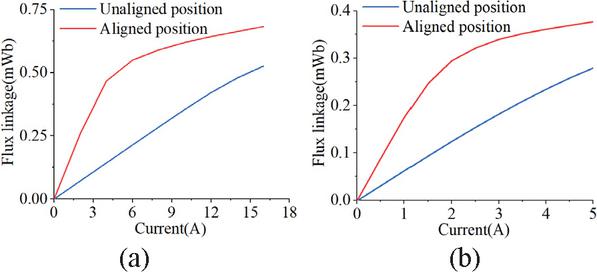
Figure 11 Flux linkage curve: (a) rotary motion and (b) linear motion.
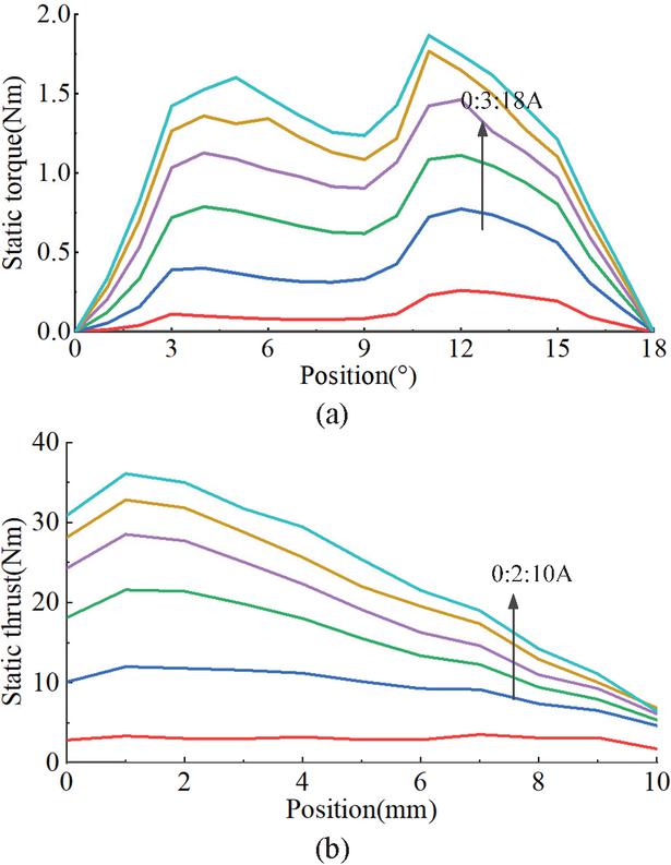
Figure 12 Static torque and static thrust curves: (a) rotary motion and (b) linear motion.
It can be observed that in the non-aligned state, the magnetic flux and current maintain an approximately linear relationship, reflecting a larger air gap and higher magnetic resistance in the magnetic circuit at this time, with the core material consistently operating in the non-saturated region. At the alignment position, the magnetic flux exhibits linear growth at lower currents; when the current increases significantly, the growth rate slows markedly, demonstrating typical nonlinear saturation characteristics. This phenomenon arises because at alignment, magnetic flux concentrates through the stator and rotor/armature, forming a low-magnetic-resistance path. This causes the local magnetic flux density in the core to rapidly increase into the saturation region, reducing magnetic permeability and thereby diminishing the magnetic flux’s ability to increase with current.
5 CONCLUSION
This study designed and validated a tubular linear-rotary switch reluctance motor employing a modular stator configuration. Through three-dimensional electromagnetic field simulation and static characteristic analysis, the magnetic field distribution patterns of this topology and its coupling characteristics under compound motion conditions were systematically evaluated. Simulation data indicates that electromagnetic interference from the linear motion unit to the rotational unit remains at a low level: under rated conditions, torque fluctuations induced by the linear winding excitation exhibit limited amplitude, with static average torque deviation consistently controlled within 5%. Concurrently, radial force fluctuations generated during motion fall within engineering application standards. These characteristics fully demonstrate that the proposed motor structure exhibits excellent electromagnetic decoupling performance when achieving combined rotational and linear motion, providing an effective technical solution for multi-degree-of-freedom drive systems.
Building on these static results, future work will focus on constructing a prototype for experimental validation. Subsequent research will also explore optimizing the stator dimensions to maximize power density, along with developing dynamic control strategies for the linear and rotary motions.
ACKNOWLEDGMENT
This work is supported by the National Natural Science Foundation of China International (regional) cooperation and exchange projects NSFC-RSF under Grant W2412064 and the Shenzhen Collaborative Innovation Special Plan International Cooperation Research Project under Grant GJHZ20240218114300002.
REFERENCES
[1] H. Chen, R. Nie, and X. Li, “A transverse-flux single-phase tubular switched reluctance linear machine with 4 poles,” IEEE Transactions on Applied Superconductivity, vol. 31, no. 8, pp. 1–4, Nov. 2021.
[2] K. Manohar and K. Srichandan, “Analysis of quadrupole magnetic field reluctance-based launcher with different coil switching patterns,” IEEE Transactions on Plasma Science, vol. 51, no. 5, pp. 1370–1376, May 2023.
[3] L. Zhang, L. Yan, X. Wei, H. Su, Z. Dong, and L. Li, “Stress analysis of a flat linear switched reluctance motor with double excitation windings,” in CSAA/IET International Conference on Aircraft Utility Systems, Nanchang, China, pp. 1240–1245, 2022.
[4] L. Szabó, “On the use of rotary-linear generators in floating hybrid wind and wave energy conversion systems,” in 2018 IEEE International Conference on Automation, Quality and Testing, Robotics, Cluj-Napoca, Romania, pp. 1–6, 2018.
[5] R. Nie, J. Si, Y. Jia, P. Wang, S. Xu, and J. Liang, “Comprehensive comparison of mover-PM and stator-PM linear-rotary generators for wind-wave combined energy conversion system,” IEEE Transactions on Industry Applications, vol. 60, no. 4, pp. 6170–6185, July–Aug. 2024.
[6] J. Zhang, M. Chen, and Y. Liu, “A tubular linear-rotary generator with dual stators for direct drive wind-wave complementary energy generation platform,” IEEE Access, vol. 13, pp. 132426–132439, 2025.
[7] H. Chen, R. Nie, and H. Wang, “A transverse flux single-phase tubular-switched reluctance linear launcher with 8-pole structure,” IEEE Transactions on Plasma Science, vol. 47, no. 5, pp. 2331–2338, May 2019.
[8] L. Szabó, I. Benţia, and M. Ruba, “A rotary-linear switched reluctance motor for automotive applications,” in 2012 XXth International Conference on Electrical Machines, Marseille, France, pp. 2615–2621, 2012.
[9] I. Benţia, L. Szabó, and M. Ruba, “On a rotary-linear switched reluctance motor,” in International Symposium on Power Electronics Power Electronics, Electrical Drives, Automation and Motion, Sorrento, Italy, pp. 507–510, 2012.
[10] I. Benţia, M. Ruba, and L. Szabó, “On the control of a rotary-linear switched reluctance motor,” in 2011 5th International Symposium on Computational Intelligence and Intelligent Informatics, Floriana, Malta, pp. 41–46, 2011.
[11] W. Wu, J. B. Dunlop, S. J. Collocott, and B. A. Kalan, “Design optimization of a switched reluctance motor by electromagnetic and thermal finite-element analysis,” IEEE Transactions on Magnetics, vol. 39, no. 5, pp. 3334–3336, Sep. 2003.
[12] H. Chen, X. Wang, C. Liu, M. F. Shamiyev, A. O. Pulatov, and A. Musolino, “Design of a three-phase high torque density modular linear rotary switched reluctance launcher,” IEEE Transactions on Plasma Science, vol. 53, no. 10, pp. 2653–2661, Oct. 2025.
[13] H. Chen, X. Wang, C. Liu, A. Musolino, P. Rafajdus, and X. Li, “Flux characteristics analysis of a novel two-degree-of-freedom tubular linear rotary switched reluctance machine,” IEEE Transactions on Plasma Science, vol. 53, no. 10, pp. 2704–2711, Oct. 2025.
[14] F. Xinghe, W. Jianhao, and L. Mingyao, “Design and analysis of linear rotary permanent magnet generator for wind-wave combined power generation system,” in 2017 20th International Conference on Electrical Machines and Systems, Sydney, NSW, Australia, pp. 1–6, 2017.
BIOGRAPHIES

Hao Chen (SM’08) received the B.S. and Ph.D. degrees from the Department of Automatic Control, Nanjing University of Aeronautics and Astronautics, Nanjing, China, in 1991 and 1996, respectively. In 1998, he became an Associate Professor with the School of Information and Electrical Engineering, China University of Mining and Technology, Xuzhou, where he has been a Professor since 2001. From 2002 to 2003, he was a Visiting Professor at Kyungsung University, Busan, Korea. Since 2008, he has also been an Adjunct Professor at the University of Western Australia, Perth, Australia. He is the author of one book and has also authored more than 190 papers. He is the holder of 15 US Patents, 23 Australian Patents, one Danish Patent, seven Canadian Patents, three South African Patents, 10 Russian Patents, 86 Chinese Invention Patents, and six Chinese Utility Model Patents. His current research interests include motor control, linear launcher, electric vehicles, electric traction, servo drives, and wind power generator control.
Chen was the recipient of both the Prize of Science and Technology of Chinese Youth and the Prize of the Fok Ying Tong Education Foundation for Youth Teachers in both 2004. He was awarded the first prize in the Science and Technology advanced of Province and Ministry once, the second prize in the Science and Technology advanced of Province and Ministry seven times, and the third prize in the Science and Technology advanced of Province and Ministry 14 times. He became the Chinese New Century Hundred-Thousand Ten-Thousand Talents Engineering National Talent in 2007, and won the Government Especial Allowance of People’s Republic of China State Department since 2006.

Cheng Liu received the B.S. degree in electrical engineering and automation from Hubei University of Technology, Wuhan, Hubei, China, in 2020, and the M.S. degree in electrical engineering from Hubei University of Technology, Wuhan, Hubei, in 2023. He is currently pursuing a Ph.D. degree in electrical engineering at China University of Mining and Technology, Xuzhou. His research interests include switched reluctance motor design control, ocean wave power generation, and electric vehicles.

Marcin Wardach was born in Poland in 1980. He graduated and received the Ph.D. degree from the Electrical Department, Szczecin University of Technology, Szczecin, in 2004 and 2009, respectively. From 2020 until now, he has been an Associate Professor with the Faculty of Electrical Engineering, West Pomeranian University of Technology in Szczecin. Since 2024, he has served as Vice-Dean for Organization and Development and Head of the Department of Electrical Machines and Drives at the Faculty of Electrical Engineering, West Pomeranian University of Technology in Szczecin. From 2019 to 2025, he worked as an electrical machine designer at mPower Sp. z o.o. company. His research interests include the design of electrical machines and drives, especially unconventional and hybrid excited. He is the author of over 100 scientific papers and post-conference publications. Since 2022, he has been the President of the Szczecin Branch of the Association of Polish Electrical Engineers (SEP). He is also a member of the Polish Society of Theoretical and Applied Electrical Engineering.

Javokhir Toshov currently works at the Department of Mining Electromechanics, Tashkent State Technical University, Uzbekistan. Toshov does research in Mechanical Engineering and Mining Engineering. Department of Electronic Devices Manufacturing Technologies, Faculty of Electronic and Automation Engineering, Tashkent State Technical University, Tashkent 100095, Uzbekistan; Department of Theoretical and Experimental Physics, Faculty of Physics, Karshi State University, Karshi 180119, Uzbekistan.

Xing Wang received the B.S. degree from China University of Mining and Technology, Xuzhou Jiangsu, China, in 1996, and M.S. degree from China University of Mining and Technology, Xuzhou Jiangsu, in 1999. In 2007, she became an Associate Professor with China University of Mining and Technology, Xuzhou. She is a holder of four US Patents, nine Australian Patents, two Canadian Patents, four Russian Patents, 12 Chinese Invention Patents, three Chinese Utility Model Patents, and authored 15 papers.

Ali Asghar Memon is professor in Electrical Engineering at Mehran University of Engineering and Technology Jamshoro, Pakistan. He holds B.E and M.E in Electrical Engineering from Mehran University and Ph.D. from University of Leeds, UK. Memon is head of Electrical Machine and Drives group at Mehran University. He has been member of National Curriculum Review Committee in Pakistan. Memon has been serving as an expert evaluator for National Research Project for Universities (NRPU), Post doc fellowship and project(s) under Technology Development Fund (TDF), under Higher Education Commission (HEC), Government of Pakistan. Memon is a keynote speaker and reviewer of prestige international research journals. Memon’s interests include modeling and simulation of switched reluctance machines and inverters.

Bodrenkov Evgenii Alexandrovich received the B.S. and M.S. degree from Federal State Budgetary Educational Institution of Higher Education Amur State University, Ph.D. degrees from Federal State Autonomous Educational Institution of Higher Education Peter the Great St. Petersburg Polytechnic University.

Popov Stanislav Olegovich received the M.S. degree in the field of “Electric power plants and automation of power systems” in 2008, and Ph.D. in Technical Sciences. He has been an associate professor at the Institute of Energy, from 2008 to present in SPBSTU.

Nikolay Korovkin (Member, IEEE) received the M.S., Ph.D., and Doctorate degrees in electrical engineering from the State Polytechnic University, Saint Petersburg, Russia, in 1977, 1984, and 1995, respectively. He is currently a Professor with the Institute of Energy, Peter the Great Saint Petersburg Polytechnic University, Saint Petersburg. Since 1996, he has been an Academician with the Academy of Electrotechnical of Russian Federation, Saint Petersburg. He has about 300 published and reviewed works in Russia and abroad. His main research interests include the inverse problems in electromagnetics, systems described by stiff equations, ill conditioned problems, optimization of power networks, optimization of the location FACTS and PMU-devices, SMART grid technologies, methods for the analysis of reliability and ensuring power balance in EPS, methods of multicriteria optimization and their application to steady-state processes in power networks, transients in transmission line systems, impulse processes in linear and nonlinear systems, problems of the electromagnetic prediction of earthquakes, and identification of the behavior of the biological objects under the influence of the electromagnetic fields.

Sakhno Liudmila (Member, IEEE) received the B.S., M.S., and Ph.D. degrees from Russia Polytechnic Institute, Saint Petersburg, Russia, in 1972, 1974, and 1982, respectively, and the Doctors degree in electromechanics and electrical apparatus from St. Petersburg State Technical University, Saint Petersburg, in 2006. She is currently a Professor of Higher School of High Voltage Power Engineering, Peter the Great Saint Petersburg Polytechnic University, Saint Petersburg. She has about 200 published and reviewed works in Russia and abroad. Her research interests include the electromagnetic problems in power transformers, the skin effect and the proximity effect in the windings of converter transformers, electromagnetic and thermal characteristics of arc and resistance welding transformers, mechanical strength of structural elements under the action of loads, and field-circuit modeling in high frequency resistance spot welding systems. She obtained eight Russian Federation Patents.

Emmanuel Karapidakis is an Electrical and Computer Engineer. He was Dean at School of Engineering from 2019 to 2025, and Director of Energy, Environment and Climate Change Institute – IEECC (http://ieecc.hmu.grieecc.hmu.gr) in Hellenic Mediterranean University – HMU (http://hmu.grhmu.gr). Since 2022, he is President of the Board in Hellenic Association of Electricity Storage Systems HAESS (http://www.haess.grwww.haess.gr). His research interest focuses on Energy Systems, Power Systems Operation, Diverse & Dispersed Generation, Micro-Grids, Renewable Energy Technologies, Energy Storage, and Energy Markets. He is/was scientific coordinator (PI) in 12 European financed projects, 15 National programs, and several private funded projects, with more than 8 million euros in total. He has published more than 120 papers (Scopus Author ID 6506872824) in prestigious journals and scientific conferences, and four scientific book chapters. From 2011 to 2015, he was Member of the Board in Regional Council of Innovation, and from 2015 to 2017, Member of Board in Energy Planning Council at Region of Crete.

Aris Dimeas is an Assistant Professor at the School of Electrical and Computer Engineering of the National Technical University of Athens (NTUA), with more than 20 years of experience in power systems operation, smart grids, and energy system digitalization. His expertise spans distribution and transmission system operation, renewable energy integration, microgrids, flexibility markets, artificial intelligence applications, and advanced control and decision-support software. He has played a leading technical and coordination role in more than 30 EU-funded research and innovation projects (H2020 and Horizon Europe), collaborating closely with TSOs, DSOs, regulators, industry, and the European Commission. His work bridges research and real-world deployment, with demonstrated impact on system supervision, resilience, market design, and datadriven grid operation, while his scientific contributions include high-impact publications in leading IEEE and international journals.

Sherif Moussa is the Dean of the School of Engineering, Applied Science, and Technology at the Canadian University Dubai (CUD), UAE. He earned his Ph.D. in Electrical and Computer Engineering from the University of Québec at Trois-Rivières, Canada, and his M.Sc. in Electrical and Computer Engineering from the University of Waterloo, Canada. Since joining CUD in 2007, Moussa has led the School’s remarkable growth, overseeing the launch and accreditation of several engineering and computing programs, including Mechatronics Engineering, Computer Science, Cybersecurity, Software Design, Power and Renewable Energy Engineering, and the M.Sc. in Artificial Intelligence. His leadership has also advanced international collaborations, notably with Queen’s University and the University of Ottawa, and strengthened CUD’s engagement with industry partners in emerging technologies. Moussa’s research interests span wireless communication, computer networks, machine learning, and digital systems design. He has published widely in international journals and conferences, serves on technical committees, and is the recipient of the 2015 CUD Research Excellence Award. He is also the founder of CUD’s Robotics Club and a strong advocate for innovation and experiential learning in engineering education.

Habes Ali Khawaldeh (Member, IEEE) received the B.E. degree in electrical and computer engineering from The Hashemite University, Jordan, in 2009, and the M.S. degree in electrical power engineering from Yarmouk University, in 2013. In 2022, Habes Ali Khawaldeh received his Ph.D. degree in power electronics engineering from the Faculty of Engineering and Information Technology, University of Technology Sydney (UTS), Australia. Since 2018, he has been a Casual Academician with UTS for various power electronics subjects. Since July 2009, he has been working as an electrical engineer with different companies in Jordan. He was a part-time Faculty Member with Yarmouk University for various power electronics subjects. He was a full-time Faculty Member with Al-Hussein Bin Talal University from 2015 to 2018. His current research interests include renewable energy (RE) systems, power converter design for RE applications, battery systems, multi-port DC/DC converters, and energy conversion systems for the smart grid. He received a Grant from Al al-Bayt University for his Ph.D. degree. He is currently a reviewer for several IEEE, IET, and Elsevier journals. Currently, Habes Ali Khawaldeh is an assistant professor at the University of Al al-Bayt in Jordan.
ACES JOURNAL, Vol. 41, No. 6, 500–511
DOI: 10.13052/2026.ACES.J.410602
© 2026 River Publishers