A Dual-Port Integrated Switched Reluctance Motor Power Converter for Electric Vehicles With Flexible Braking and Energy Recovery
Chenhe Zhang1, Hao Chen1, Olimjon Toirov2, Sherif Moussa3, Habes Ali Khawaldeh4, Marcin Wardach5, Sergei Brovanov6, Ali Asghar Memon7, Emmanuel Karapidakis8, and Aris Dimeas9
1School of Electrical Engineering China University of Mining and Technology, Xuzhou 221116, China
1364573229@qq.com, hchen@cumt.edu.cn
2Tashkent State Technical University University Street No2, 100095 Tashkent, Uzbekistan
olimjon.t@mail.ru
3School of Engineering Canadian University Dubai, Dubai, UAE 117781, Sheikh Zayed Road, Dubai, United Arab Emirates
smoussa@cud.ac.ae
4The Renewable Energy Engineering Department Faculty of Engineering, Al al-Bayt University, Mafraq, Jordan
habes.a.khawaldeh@aabu.edu.jo
5West Pomeranian University of Technology Sikorskiego 37, 70-313 Szczecin, Poland
Marcin.Wardach@zut.edu.pl
6Novosibirsk State Technical University Novosibirsk 630073, Russia
brovanov@corp.nstu.ru
7Mehran University of Engineering and Technology Electrical Engineering, Jamshoro, Pakistan
Pakistanali.asghar@faculty.muet.edu.pk
8School of Engineering Hellenic Mediterranean University, Estavromenos Campus, 71004 Heraklio, Crete, Greece
9Athens National University of Technology Greece
*Corresponding author
Submitted On: January 18, 2026
Accepted On: June 10, 2026
ABSTRACT
As environmental protection increasingly becomes a global focus, new energy vehicles have gradually emerged as a rising star in the modern transportation sector. They not only represent technological innovation but also carry the hope of achieving sustainable mobility. This paper proposes a novel dual-port integrated power converter, consisting of a front-end circuit and a traditional asymmetric half-bridge converter. By changing the operating state of the front-end circuit’s switch transistors, different operating modes can be switched. In the motoring state, there are single-power supply mode and hybrid power supply mode, and the converter is reconfigured into a five-level converter. In the regenerative braking mode, there are moderate braking mode and severe braking mode, and energy recovery can be achieved in both modes, with the converter being reconfigured into a four-level converter. The power converter proposed in this paper can accommodate wide speed range regulation for both electric and braking operations, while also recovering energy from regenerative braking. It has been simulated and verified on a three-phase 12/8 switched reluctance motor, confirming its practicality and effectiveness.
Keywords: Multilevel, regenerative braking, switched reluctance motor..
1 INTRODUCTION
Against the backdrop of actively addressing climate change and vigorously promoting energy transformation worldwide, electric vehicles are like a rising star, rapidly becoming the mainstream direction of the automotive industry’s development with their significant advantages of cleanliness, environmental protection, high efficiency, and energy conservation, leading the transportation sector to accelerate towards a green, intelligent, and sustainable future. As one of the components of the power system of electric vehicles, the motor plays an extremely important role. The strong magnetic field characteristics of the permanent magnet in the permanent magnet synchronous motor make its structure more compact and capable of outputting greater power in a limited space, which is very suitable for the lightweight and high power needs of electric vehicles. However, its core cost lies in the permanent magnet, which is greatly affected by the high cost of rare earths. Thus, there is an urgent need for a rare earth free motor, and switched reluctance motors (SRMs) have received widespread attention in this field. The rotor has no permanent magnets and windings, and is made of stacked silicon steel sheets. The stator winding structure is simple, with a low failure rate and almost no maintenance required, which enables it to be applied in scenarios such as high speed, high temperature, and high torque.
SRM drive topology with multi-power supply and multi-port has the characteristics of integration, high reliability, and strong applicability, which has gradually attracted the attention of scholars and engineers. In addition, in high-speed operation, the traditional SRM drive system is usually limited by the constant DC bus voltage, which makes the excitation and demagnetization voltage fixed, and it is difficult to realize the rapid excitation and demagnetization of the winding, thus affecting the efficiency, output energy, and dynamic performance of the motor system. A multilevel power conversion circuit can realize the fast excitation and demagnetization of windings, which is an effective scheme to improve the driving performance of SRM [1].
Ali and Narimani suggested an eight-leg asymmetric three-level power converter, which divides the batteries into two groups and produces a similar working mode as the traditional three-level asymmetric converter. It has improved performance, reduced size, and is different from the series connected single battery pack. The proposed battery pack separate connection provides flexible control and fault tolerance for SRM driver [2]. Hu et al. proposed a SRM drive system for electric vehicles based on battery/super capacitor. The system has G2V and V2H/V2G functions. The power circuit of the motor drive system is composed of bidirectional two quadrant front-end DC/DC converter and SRM asymmetrical bridge converter. Through reasonable control and key parameter setting, good acceleration/deceleration, reversible drive, and braking characteristics are obtained [3]. A highly integrated modular converter for SRM of extended range electric vehicle is proposed by Xia and Bauman [4]. The converter can be realized by a standard industrial switch module, and can flexibly realize the energy conversion between SRM, battery, generator, and external AC power supply through front-end circuit. In the battery driven mode, the capacitor in parallel with the generator is naturally charged and discharged, which improves the phase voltage, accelerates the excitation and demagnetization process of SRM, and improves the torque capacity of SRM. In the generator driven mode, the battery also participates in the rapid excitation and demagnetization of SRM.
Yu et al. suggested a simplified dual-port driver for flux modulated SRM with flexible charging capability for electric vehicle applications in [5]. Using modular three-phase converter and auxiliary battery, the corresponding pulse width modulation (PWM) control method was studied, and a current regulator based on VPI was proposed, which further improved the performance of the motor, realized flexible power control and battery charging, and a variety of driving and charging modes. Phase current regulation of SRMs driven by traditional asymmetric half-bridge power converters (AHB) is limited by the supply voltage. Thus an improved capacitor voltage self-balancing active boost power converter is proposed by Han and Chen in [6]. The problems of an AHB power converter in different phases of each phase current were analyzed, the different working modes of the converter were studied, and the corresponding control strategies implemented.
A motor driver for a four-phase SRM with only two current sensors is presented in [7]. The driver uses an asymmetric half-bridge circuit, but each current of the two windings is detected by a current sensor, which enables the proposed SRM driver to provide additional charge/discharge functions without adding any additional circuit elements. Additional current sensors, implementation of the integrated driver, and proof of the results is provided. A modular three-port converter with simple structure is proposed in [8], which organically combines the generator, battery, and SRM. A bidirectional front-end circuit with a photovoltaic (PV) power supply is designed in [9], which integrates the electrical components into a converter and realizes six driving modes and five charging modes to obtain multilevel voltage and increased torque capacity. A highly integrated solar assisted SRM drive system, which has the functions of electric drive reconfiguration of G2V and V2G/V2L, realizes flexible and efficient multi-mode energy transmission between SRM, battery pack, solar PV panel, and AC grid in [10]. In order to extend the driving range of electric vehicles, the use of PV panels on vehicles helps to reduce the dependence on on-board batteries. Based on the phase winding characteristics of SRM, a three-port converter is used to control the energy flow between PV cells, batteries, and SRMs in [11].
This paper is structured as follows. Section 2 introduces the components of the power converter. Section 3 gives its various working states and characteristics. Section 4 is simulation verification, and section 5 draws conclusions.
2 STRUCTURE AND PERFORMANCE ANALYSIS OF THREE-PHASE SRM
The stator and rotor of SRM are of salient pole structure and are laminated by silicon steel sheets (reducing iron consumption). The rotor has no windings and permanent magnets, and the structure is simple and reliable. Single-phase, two-phase, three-phase, and four-phase structures are common, and three-phase SRM is the most widely used. The winding current is a unidirectional pulse current, which is provided by the power converter [12]. According to the law of conservation of energy and the law of electromagnetic induction, the voltage applied to each stator winding is equal to the sum of the resistance voltage drop and the induced electromotive force generated due to the change of flux linkage, and the relationship between the voltage, current, and flux linkage of phase of the motor is:
| (1) |
When the given excitation current is high, the electromagnetic characteristics will show nonlinearity due to the saturation of the magnetic core. In general, for the convenience of calculation, the mutual inductance between the windings of SRM is often not considered. The magnetic circuit and inductance are functions of current and rotor position. Flux linkage can be calculated by the product of winding inductance and current:
| (2) |
Combining Equations (1) and (2), there is an electric potential balance equation:
| (3) |
Equation (3) reveals that the terminal voltage of each phase winding in a SRM is balanced by three distinct voltage components within the circuit: the resistive voltage drop, the transformer electromotive force, and the motional electromotive force [13].
Given the magnetic circuit nonlinearity inherent in SRMs, the electromagnetic torque at an arbitrary operating point can be derived via the principle of virtual displacement – specifically, as the partial derivative of the magnetic co-energy with respect to the rotor position – and is expressed by:
| (4) |
Combined with the piecewise linear model of inductance, the torque expression of each interval can be further derived. In non-overlapping/aligned areas, . Torque is zero. In overlapping areas:
| (5) |
where C is a constant and torque is proportional to the square of the current. In addition, the equation of mechanical motion of the motor is:
| (6) |
where , and are moment of inertia, viscous coefficient, rotor angular velocity, electromagnetic torque, and load torque, respectively [14].
Let us take the 12/8 three-phase SRM (12-pole stator, 8-pole rotor, three-phase concentrated winding) as an example (see Fig. 1). Its core advantages lie in the stability of operation, fault tolerance, structural reliability, and wide speed regulation range. The stepping angle is (half of compared with 6/4 three-phase SRM), torque superposition is more continuous, fundamental frequency of torque ripple is increased, and low-speed stepping sense is weakened, which is conducive to improving the stability of operation and reducing vibration and noise [15].
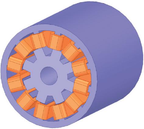
Figure 1 Three-phase 12/8 SRM structure.
Figure 2 shows a 3D diagram of a 12/8 three-phase SRM static flux linkage. The data in Fig. 2 is obtained through simulation in ANSYS, in which the current is simulated at the interval of 0 A to 100 A, and the rotor position is simulated at the interval of to . Intermediate data points are obtained by linear interpolation method. As can be seen from Fig. 2, the minimum value of the flux linkage appears in the fully misaligned position, while the maximum value appears in the fully aligned position. Flux linkage increases gradually in the range and decreases gradually in the range .
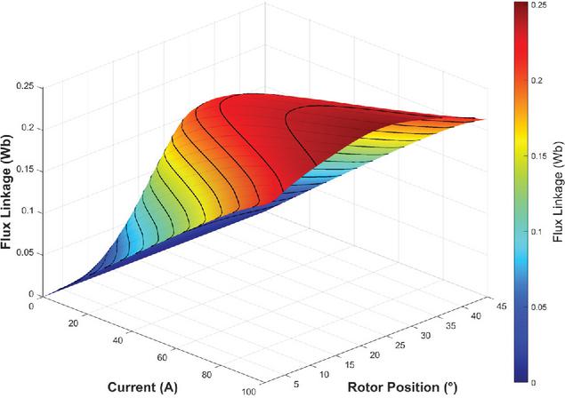
Figure 2 Three-dimensional view of the static flux linkage of 12-8 SRM.
Figure 3 shows a three-dimensional view of its static torque. The data in Fig. 3 is obtained through ANSYS finite element simulation, in which the current simulation interval is 0 A to 100 A, the rotor position simulation interval is to , and the rotor angle cycle is . It can be seen from Fig. 3 that the static torque of SRM is positive in the range and negative in the range .
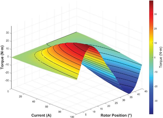
Figure 3 Three-dimensional view of static torque of 12/8 SRM.
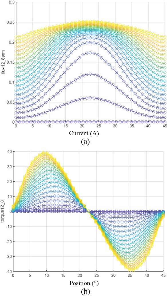
Figure 4 Phase torque and phase flux linkage at different angles and currents: (a) static flux linkage line curve and (b) static torque curve.
Figure 4 illustrates the variations in static torque and flux linkage of the SRM under single-phase excitation, with both parameters characterized across different rotor angles and winding currents. It is evident that the flux linkage magnitude of the SRM increases alongside the winding current during the rotor’s movement from the unaligned to the aligned position relative to the excited stator pole. In particular, flux linkage at the unaligned position exhibits a linear relationship with the current, which indicates that the motor operates in a magnetically unsaturated state under this condition.
3 DRIVING CHARACTERISTICS OF DUAL-PORT INTEGRATED SRM POWER CONVERTER
Figure 5 shows the topology of the dual-port integrated SRM power converter proposed in this paper for a three-phase 12/8 structure SRM. It is mainly composed of front-end circuit and traditional AHB, taking into account the electric and braking states of electric vehicle operation, and can achieve energy recovery in the braking state. The front-end circuit includes four switch tubes, two diodes, a power supply, and a power battery. By controlling the on and off of the front-end circuit switch tubes, multiple functions and operating modes of the electric vehicle can be achieved. The electric vehicle power system based on SRM is shown in Fig. 6 [15].
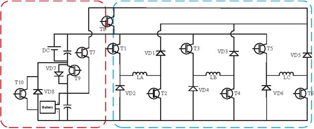
Figure 5 Topology of dual-port integrated SRM converter.
The power converter proposed in this paper includes electric mode, multilevel mode, and hybrid power mode of power battery. Due to the addition of multilevel mode, the output torque and load capacity of the motor have been significantly improved. In the power drive mode, the battery does not participate in power supply, but rapid demagnetization can be achieved by increasing the demagnetization voltage through series connection of batteries. In hybrid driving mode, the motor is driven in series by a power source and a battery to improve its dynamic performance [16]. The power supply and battery can be matched according to different working conditions to improve dynamic performance. In addition, in the braking state, it is possible to achieve two modes of braking while also considering energy recovery. Moderate braking is excited by the power supply alone, and the battery recovers energy. Heavy braking is excited by both the power supply and the battery, while the battery recovers energy, to cope with different braking situations and achieve more flexible braking.
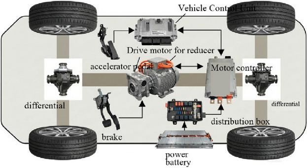
Figure 6 Electric vehicle power system.
The proposed power converter has a total of six working states: power excitation, power demagnetization, hybrid excitation, hybrid demagnetization, zero voltage demagnetization, and energy recovery. The electric mode includes five working states, and the braking mode includes four working states. The components used in the power converter proposed in this article are shown in Table 1.
Table 1 Composition of power converter components [17]
| Component | Type Number | Quantity |
| Mosfet | IRFP4668 | 10 |
| Diode | RURG8060 | 8 |
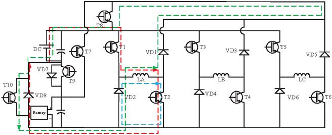
Figure 7 Working status of power drive.
3.1 Single power drive mode
In single power drive mode, there are three states: power excitation, zero voltage freewheeling, and power demagnetization, as shown in Fig. 7. In the excitation state of the power supply, the current passes through the asymmetric half-bridge circuit, flows through the negative pole of the power battery, and then forms an excitation circuit through the reverse diode connected in parallel with the switching transistor , and the current rises rapidly. The voltage applied to the winding at this time is , as shown by the red dotted line in Fig. 7. Afterwards, by controlling the switching tubes , and separately, the A, B, and C phase windings are controlled for zero voltage freewheeling, resulting in zero winding voltage, as shown by the blue dotted line in the Fig. 7. In demagnetization mode, the control switch tubes and are turned on, and the phase current forms a demagnetization circuit through the switch tubes and . A reverse voltage is applied to the winding for reverse demagnetization, as shown by the green dotted line in the Fig. 7. Therefore, in the electric single power supply mode, only the and switching tubes need to be controlled to conduct.
3.2 Hybrid driving mode
In hybrid driving mode, there are three states: hybrid excitation, zero voltage freewheeling, and hybrid demagnetization, as shown in Fig. 8. In this mode, the power supply is connected in series with the battery, and both the excitation voltage and demagnetization voltage are increased, achieving fast excitation and fast freewheeling, improving the output capability of the motor torque and enhancing the dynamic performance of the motor. In excitation mode, current flows through the switch and the AHB converter to form an excitation circuit, achieving fast excitation. The voltage applied to the winding is the sum of the power supply voltage and the battery voltage , as shown by the red dotted line in the Fig. 8. We can control the A, B, and C phase windings for zero voltage freewheeling by separately controlling the switching tubes , and , as shown by the blue dotted line in Fig. 8. In demagnetization mode, the current passes through the reverse diode of the switching tubes and to form a circuit for demagnetization, achieving rapid demagnetization in the reverse direction. The voltage applied to the winding is , as shown by the green dotted line in Fig. 8. Therefore, in the hybrid power supply mode of electric state, only the two switching tubes and need to be controlled to conduct.
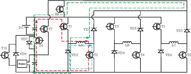
Figure 8 Working status of hybrid drive.
3.3 Moderate braking mode
During normal braking, the SRM speed is low and the back electromotive force is small. A combination of current chopping control (CCC) and PWM is used to control the on-off of power devices through PWM signals, stabilizing the braking current at the set value and maintaining a constant braking torque. In normal situations where braking is required, power excitation can be used to apply voltage to the winding during the rise of the inductor, generating braking current. In the decrease interval of the inductor, negative torque and generating current can be generated to reduce the speed and charge the battery. Due to the combination of front-end circuit and traditional asymmetric half-bridge, phase overlap can be achieved in the braking state. In normal braking mode, when phase A recovers energy and phase B excites, the phase overlap situation is shown in Fig. 9.
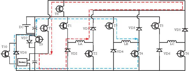
Figure 9 Phase overlap under moderate braking conditions.
The blue dashed line in Fig. 9 indicates that the B-phase winding is being excited, and the switching tubes and are open, causing a rapid increase in winding current. The red dashed line indicates that the A-phase winding is undergoing energy recovery, and the braking energy flows to the battery through switch tube .
3.4 Heavy braking mode
In emergency situations where strong braking is required, the power supply is connected in series with the battery and voltage is applied to the winding during the rise of the inductance to jointly excite it, achieving a rapid increase in braking current and generating negative torque quickly. This can greatly improve the braking performance of the motor and, while ensuring braking, the braking energy can still be recovered by flowing through the switch tube to the battery. In heavy braking mode, when phase A recovers energy and phase B excites, the phase overlap situation is shown in Fig. 10.
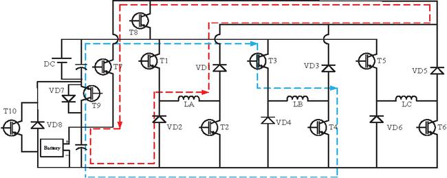
Figure 10 Phase overlap under heavy braking conditions.
Similar to Fig. 9, the blue dashed line in Fig. 10 indicates that the B-phase winding is being excited, and the switching tubes and are open, causing the winding current to rise more rapidly. The red dashed line indicates that the A-phase winding is undergoing energy recovery, and the braking energy is still flowing to the battery through switch tube .
3.5 Converter driving characteristics
The proposed switched reluctance power converter adopts different working states according to different operating conditions, as shown in Fig. 11.
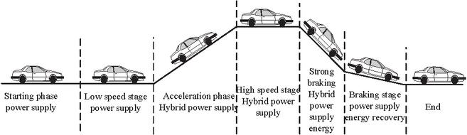
Figure 11 Working modes under different working conditions.
In the starting and low-speed states, power supply is used for this condition, with power excitation and demagnetization [18]. Power batteries can be connected in series for demagnetization. In the rapid acceleration stage and high-speed stage, a hybrid driving mode is adopted, in which the power supply and battery are connected in series to participate, and the power supply and battery are connected in series to jointly excite and demagnetize, thereby increasing the excitation voltage and demagnetization voltage and improving the output performance of the motor. In the case of heavy braking, a multilevel SRM power converter can ensure the simultaneous use of two power sources during motor operation by mixing power and battery excitation, and recovering battery energy. We can select the appropriate conduction mode based on the current speed, torque error, and rotor position to achieve stable operation of the motor at low speeds and timely tracking of the required current value at high speeds, thus suppressing torque ripple. This multiple power supply mode enables the motor power converter to adapt to complex and changing working conditions, improve the efficiency and stability of motor operation, and is widely used in motor drive systems encountered in various complex working conditions of electric vehicles.
4 SIMULATION RESULTS
A 1 kW three-phase 12/8-pole SRM was modeled in MATLAB/Simulink, and the proposed highly integrated converter was validated. The rated voltage of the motor is 96 V, The moment of inertia J is 0.01 , and the friction coefficient D is 0.00032 , the battery voltage and power supply voltage were set to 36 V and 60 V, the battery capacity is 5.4 Ah, initial state-of-charge is 60%, respectively, and the load torque was set to 3 . The electric mode adopted CCC, and the hysteresis current bandwidth was set to 1.5 A. Low-speed and high-speed operation were considered in the simulation. The motor section is shown in Fig. 12.
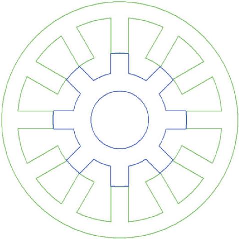
Figure 12 12/8 SRM section.
The motor adopts CCC current chopper control and obtains the reference current value through proportional-integral-derivative (PID) control. When the phase current reaches , the power switch of that phase is turned off, the power supply is cut off, and the current is attenuated through the freewheeling diode. When the phase current drops to , turn on the power switch and the current rises again. Cycle the above process to make the phase current fluctuate within the range , achieving stable control of the current amplitude. The opening angle of the motor in this simulation is set to , and the closing angle is set to .
The single power drive mode is suitable for starting and low-speed states. When the motor rotates to 600 r/min, the speed diagram and torque diagram are shown in Fig. 13.
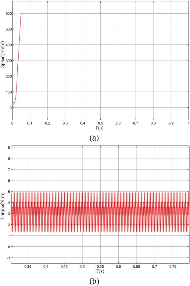
Figure 13 Simulation results of a 600 r/min single power drive mode motor: (a) speed waveform diagram and (b) torque waveform diagram.
The winding voltage in single power mode is shown in Fig. 14. It can be seen that the winding voltage mainly varies between , and 60 V, with an excitation state of 60 V. When the phase current reaches the reference current, it transitions to a freewheeling state of 0 V. When the phase reaches the turn off angle, the winding demagnetizes and the phase voltage is 60 V.
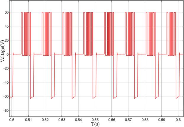
Figure 14 Single power drive winding voltage.
When the motor rotates to 1200 r/min, the speed diagram and torque diagram are shown in Fig. 15.
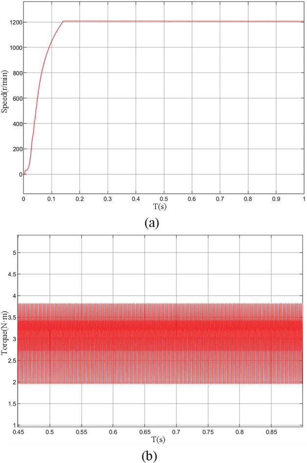
Figure 15 Simulation results of a 1200 r/min single power drive mode motor: (a) speed waveform diagram and (b) torque waveform diagram.
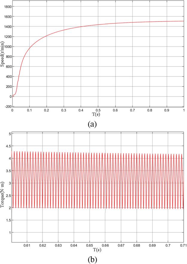
Figure 16 Simulation results of a 1600 r/min single power drive mode motor: (a) speed waveform diagram and (b) torque waveform diagram.
The winding voltage in single power mode is similar to Fig. 14. From Fig. 14, it can be seen that in single power drive mode, the motor speed can quickly increase to 1200 r/min and remain stable.
As shown in Fig. 16, in the single power excitation mode, when the target speed is 1600 r/min, the motor cannot reach the target speed and the torque ripple increases. With the conduction angle unchanged, the motor output is close to the limit. In the hybrid driving mode, the simulation results of the target speed of 1600 r/min are shown in Fig. 17. When the target speed remains constant at 1600 r/min and the load torque increases by 6 , the simulation results are shown in Fig. 18.
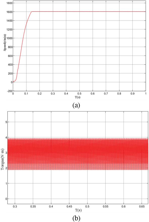
Figure 17 Simulation results of a 1600 r/min hybrid drive mode motor: (a) speed waveform diagram and (b) torque waveform diagram.
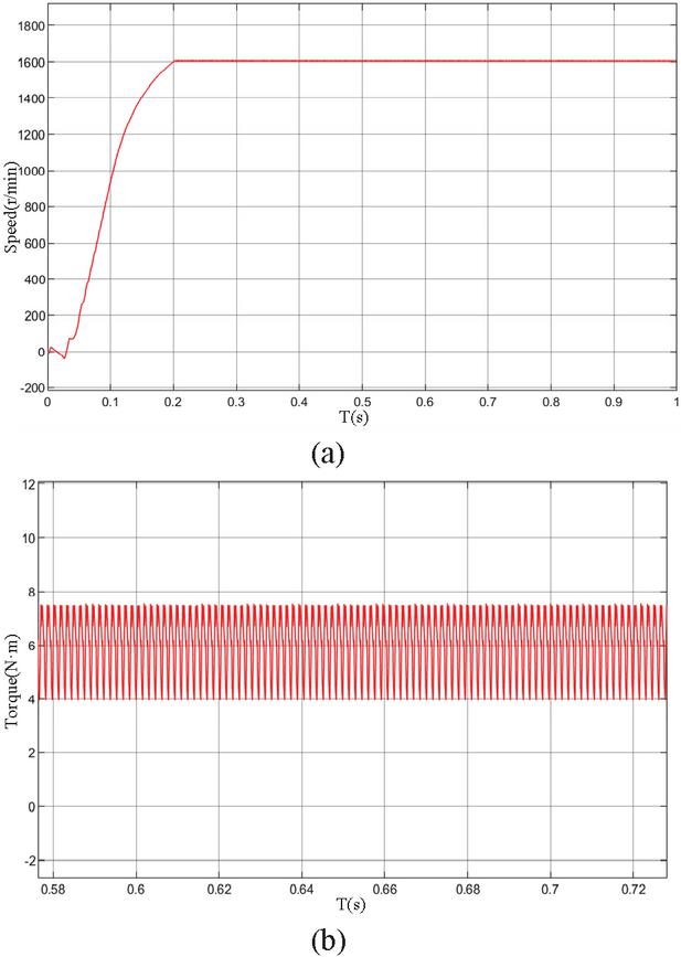
Figure 18 Simulation results of load torque at a speed of 1600 r/min: (a) speed waveform diagram and (b) torque waveform diagram.
By comparison, it can be seen that when using the hybrid mode, both the excitation voltage and demagnetization voltage are significantly increased. Under the same load torque, higher speeds can be achieved and acceleration is faster. At the same time, larger output torque can be obtained while reducing torque ripple, greatly increasing the overall performance of the motor.
In the context of brake simulation, braking commences when the motor speed reaches 2200 r/min. Under moderate braking mode, the motor simulation results are shown in Fig. 19.
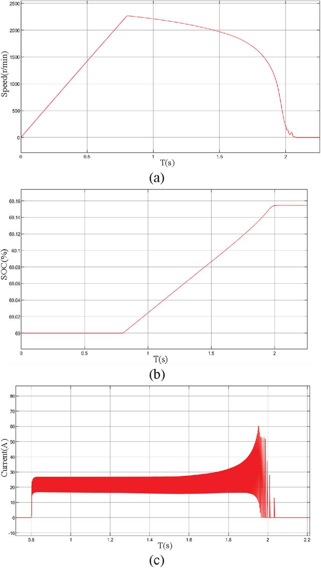
Figure 19 Simulation results of moderate braking: (a) speed waveform diagram, (b) battery SOC, and (c) charging current waveform.
Load torque is still , motor speed rises from 0 to 2200 r/min at 0.8 s, and then starts braking. In the moderate braking mode, the motor is braked to 0 r/min at 2.05 s, and braking time is about 1.25 s. SOC of the power battery is initially 60% and, after recovery of the braking dynamic energy, battery SOC increases from 60% to 60.155%, as shown in Fig. 19 (b). Energy flows towards the battery, and the charging current of the battery is shown in Fig. 19 (c).
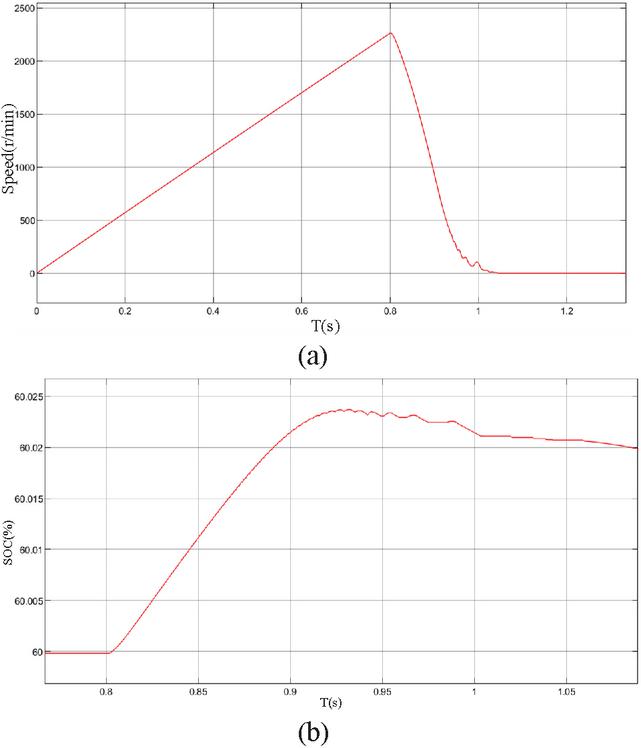
Figure 20 Simulation results of heavy braking: (a) speed waveform diagram and (b) battery SOC.
In heavy braking mode, as shown in Fig. 20, the motor speed rises from 0 to 2200 r/min at 0.8 s, and then starts braking. At 1.05 s, the motor was braked to 0 r/min, and the braking time was about 0.25 s. At the same time, the power battery recovered energy, and the battery SOC increased. During this braking process, the SOC of the battery increases from 60% to 60.024%, and the recovered energy is relatively less compared to moderate braking.
Compared with moderate braking, heavy braking can significantly improve the braking performance, so as to cope with the complex working conditions of electric vehicles and recover energy at the same time. The proposed converter has been effectively verified in terms of braking.
5 CONCLUSION
This paper proposes a dual-port integrated switched reluctance motor power converter for electric vehicles, which takes into account the electric and braking state of electric vehicles. By controlling the switching state of the front-end circuit, it can flexibly realize energy conversion between the battery, switched reluctance motor, and power supply. It not only improves the performance of the motor system under operating conditions, but also realizes the energy recovery function, realizes flexible driving and flexible braking, obtains multilevel voltage, increases torque capacity, and improves the dynamic performance of the motor as a whole. At the same time, this paper theoretically analyzes a switched reluctance motor under different working conditions, and carries out the simulation of electric and braking to verify the effectiveness of the converter.
ACKNOWLEDGMENT
This work is supported by the National Natural Science Foundation of China International (regional) cooperation and exchange projects NSFC-RSF under Grant W2412064.
REFERENCES
[1] H. Wang, Speed Regulation and Control Technology of Switched Reluctance Motors, 2nd ed. Beijing: Publishing House of Electronics Industry, 2014.
[2] N. Ali and M. Narimani, “A new three-level switched reluctance motor drive for electric vehicles,” in 2024 IEEE 21st International Power Electronics and Motion Control Conference (PEMC), Pilsen, Czech Republic, pp. 1–6, Sep. 2024. doi:10.1109/PEMC61721.2024.10726378.
[3] K.-W. Hu, P.-H. Yi, and C.-M. Liaw, “An EV SRM drive powered by battery/supercapacitor with G2V and V2H/V2G capabilities,” IEEE Trans. Ind. Electron., vol. 62, no. 8, pp. 4714–4727, Aug. 2015. doi:10.1109/TIE.2015.2396873.
[4] Z. Xia and J. Bauman, “An integrated modular converter for switched reluctance motor drives in range-extended electric vehicles,” in 2019 IEEE Transportation Electrification Conference and Expo (ITEC), Detroit, MI, USA, pp. 1–7, June 2019. doi:10.1109/ITEC.2019.8790494.
[5] Z. Yu, C. Gan, K. Ni, Y. Chen, and R. Qu, “Dual-electric-port bidirectional flux-modulated switched reluctance machine drive with multiple charging functions for electric vehicle applications,” IEEE Trans. Power Electron., vol. 36, no. 5, pp. 5818–5831, May 2021. doi: 10.1109/TPEL.2020.3029822.
[6] G. Han and H. Chen, “Improved power converter of SRM drive for electric vehicle with self-balanced capacitor voltages,” IEEE Trans. Transp. Electrific., vol. 7, no. 3, pp. 1339–1348, Sep. 2021. doi:10.1109/TTE.2020.3037111.
[7] H.-C. Chen, W.-A. Wang, and B.-W. Huang, “Integrated driving/charging/discharging battery-powered four-phase switched reluctance motor drive with two current sensors,” IEEE Trans. Power Electron., vol. 34, no. 6, pp. 5019–5022, June 2019. doi:10.1109/TPEL.2018.2880259.
[8] T. Wu, W. Li, K. Ni, S. Song, and M. Alkahtani, “Modular tri-port converter for switched reluctance motor based hybrid electrical vehicles,” IEEE Access, vol. 7, pp. 15989–15998, 2019. doi:10.1109/ACCESS.2019.2894818.
[9] C. Gan, N. Jin, Q. Sun, W. Kong, Y. Hu, and L. M. Tolbert, “Multiport bidirectional SRM drives for solar-assisted hybrid electric bus powertrain with flexible driving and self-charging functions,” IEEE Trans. Power Electron., vol. 33, no. 10, pp. 8231–8245, Oct. 2018. doi:10.1109/TPEL.2017.2780622.
[10] Q. Sun, H. Xie, X. Liu, F. Niu, and C. Gan, “Multiport PV-assisted electric-drive-reconstructed bidirectional charger with G2V and V2G/V2L functions for SRM drive-based EV application,” IEEE J. Emerg. Sel. Topics Power Electron., vol. 11, no. 3, pp. 3398–3408, June 2023. doi:10.1109/JESTPE.2023.3240434.
[11] Y. Hu, C. Gan, W. Cao, Y. Fang, S. J. Finney, and J. Wu, “Solar PV-powered SRM drive for EVs with flexible energy control functions,” IEEE Trans. on Ind. Applicat., vol. 52, no. 4, pp. 3357–3366, July 2016. doi:10.1109/TIA.2016.2533604.
[12] A. F. Dewi and S. Riyadi, “The impact of SRM rotor speed on regenerative braking to optimize the performance,” in 2019 IEEE Conference on Energy Conversion (CENCON), Yogyakarta, Indonesia, pp. 104–109, Oct. 2019. doi:10.1109/CENCON47160.2019.8974687.
[13] V. F. Pires, A. J. Pires, A. Cordeiro, and D. Foito, “A review of the power converter interfaces for switched reluctance machines,” Energies, vol. 13, no. 13, p. 3490, July 2020. doi:10.3390/en13133490.
[14] X.-H. Huang and G.-Q. Liu, “Research on brake control of switched reluctance motor,” in 2018 International Conference on Sensor Networks and Signal Processing (SNSP), Xi’an, China, pp. 361–364, Oct. 2018. doi:10.1109/SNSP.2018.00076.
[15] M. Deepak, C. Bharatiraja, S. S. Williamson, and M. Krishnamurthy, “Enhanced direct torque control of SRM based on a novel multilevel hysteresis torque band with effective voltage vectors for low torque ripple,” IEEE Transactions on Transportation Electrification, vol. 11, no. 6, pp. 12758–12770, Dec. 2025. doi:10.1109/TTE.2025.3585500.
[16] G. D. Wahyu and S. Riyadi, “PWM control strategy of regenerative braking to maximize the charging current into the battery in SRM drive,” in 2019 International Seminar on Application for Technology of Information and Communication (iSemantic), Semarang, Indonesia, pp. 523–527, Sep. 2019. doi:10.1109/ISEMANTIC.2019.8884342.
[17] X. Sun, L. Feng, Z. Zhu, G. Lei, K. Diao, and Y. Guo, “Optimal design of terminal sliding mode controller for direct torque control of SRMs,” IEEE Transactions on Transportation Electrification, vol. 8, no. 1, pp. 1445–1453, Mar. 2022. doi:10.1109/TTE.2021.3111889.
[18] M. A. Gaafar, A. Abdelmaksoud, M. Orabi, H. Chen, and M. Dardeer, “Switched reluctance motor converters for electric vehicles applications: Comparative review,” IEEE Trans. Transp. Electrific., vol. 9, no. 3, pp. 3526–3544, Sep. 2023. doi:10.1109/TTE.2022.3192429.
BIOGRAPHIES

Chenhe Zhang received the B.S. degree in electrical engineering and automation from Yancheng Institute Of Technology, Yancheng, Jiangsu, China, in 2024. He is currently pursuing a master degree in electrical engineering at China University of Mining and Technology, Xuzhou. His research interests include switched reluctance motor design control, electric traction, and electric vehicles.

Hao Chen (SM’08) received the B.S. and Ph.D. degrees from the Department of Automatic Control, Nanjing University of Aeronautics and Astronautics, Nanjing, China, in 1991 and 1996, respectively. In 1998, he became an Associate Professor with the School of Information and Electrical Engineering, China University of Mining and Technology, Xuzhou, where he has been a Professor since 2001. From 2002 to 2003, he was a Visiting Professor at Kyungsung University, Busan, Korea. Since 2008, he has also been an Adjunct Professor at the University of Western Australia, Perth, Australia. He is the author of one book and has also authored more than 190 papers. He is the holder of 15 US Patents, 23 Australian Patents, one Danish Patent, seven Canadian Patents, three South African Patents, 10 Russian Patents, 87 Chinese Invention Patents, and six Chinese Utility Model Patents. His current research interests include motor control, linear launcher, electric vehicles, electric traction, servo drives, and wind power generator control.
Chen was the recipient of both the Prize of Science and Technology of Chinese Youth and the Prize of the Fok Ying Tong Education Foundation for Youth Teachers in 2004. He was awarded first prize in the Science and Technology advanced of Province and Ministry once, second prize in the Science and Technology advanced of Province and Ministry seven times, and third prize in the Science and Technology advanced of Province and Ministry 14 times. He became the Chinese New Century Hundred-Thousand Ten-Thousand Talents Engineering National Talent in 2007, and won the Government Especial Allowance of People’s Republic of China State Department since 2006.

Olimjon Toirov earned the degree of Doctor of Philosophy (Ph.D.) in technical sciences in the specialty “Energy Systems and Complexes” at the Institute of Energy and Automation of the Academy of Sciences of the Republic of Uzbekistan in 2012. In 2018, he defended his Doctor of Technical Science (D.Sc.) dissertation at Tashkent State Technical University (TSTU). In 2020, he was awarded the academic title of Full Professor in the specialty “Energy Systems and Complexes”. Throughout his professional career, Toirov served as a research fellow at the Institute of Energy and Automation of the Academy of Sciences of the Republic of Uzbekistan from 2007 to 2016; a leading researcher and project manager at “Scientific-Technical Center”, “Uzbekenergo” from 2016 to 2017. In 2017–2018, he worked as a Senior Researcher for the UNESCO/Poland Fellowship Programme in Engineering Project, AGH University of Science and Technology (Poland) and as Head of the “Electrical Machines and Drives” Department at TSTU from 2019 to 2024. Since 2024, he has been serving as the Dean of the “Electrical Engineering” Faculty at TSTU.
Toirov’s research activities are focused on design and automatic electric drive, green energy, renewable energy sources, improving energy efficiency in electric power supply systems, control of asynchronous generators, and enhancing the efficiency of electromechanical systems. Under his leadership, automated control devices were developed and successfully implemented across several key industrial sectors, including the Almalyk and Navoi Mining and Metallurgical Combines, Uzbekhydroenergo, oil and gas enterprises, and automotive factories. He has participated in more than 50 industry-funded projects and over 15 fundamental and applied research projects and has won more than 12 international research grants. He is the author of over 300 scientific publications, including 32 inventions and patents, six textbooks, five teaching manuals, 16 methodological guidelines, and two monographs. More than 40 of his articles are indexed in Web of Science and Scopus databases. Toirov has supervised one Doctor of Technical Science (D.Sc.), five Doctors of Philosophy (Ph.D.), more than 50 bachelors’, and over 20 master’s students. He was awarded the honorary 1st place in the “Most Active Young Scientist of the Year” competition held in the Republic of Uzbekistan in 2016. In 2023, he was honored with the “Scopus Edwards Uzbekistan” award for his outstanding publication activity. He was awarded the “Shuhrat” medal by the Decree of the President of the Republic of Uzbekistan in 2024. Toirov has completed international training and research programs in countries such as China, Russia, India, South Korea, Germany, France, Azerbaijan, Belarus, Poland, Slovakia, and Belgium. He currently serves as a member of the Expert Council on energy sciences under the Higher Attestation Commission of the Republic of Uzbekistan. He is also an editorial board member of several national and international scientific journals.

Sherif Moussa is Dean of the School of Engineering, Applied Science, and Technology at the Canadian University Dubai (CUD), UAE. He earned his Ph.D. in Electrical and Computer Engineering from the University of Québec at Trois-Rivières, Canada, and his M.Sc. in Electrical and Computer Engineering from the University of Waterloo, Canada. Since joining CUD in 2007, Moussa has led the School’s remarkable growth, overseeing the launch and accreditation of several engineering and computing programs, including Mechatronics Engineering, Computer Science, Cybersecurity, Software Design, Power and Renewable Energy Engineering, and the M.Sc. in Artificial Intelligence. His leadership has also advanced international collaborations, notably with Queen’s University and the University of Ottawa, and strengthened CUD’s engagement with industry partners in emerging technologies. Moussa’s research interests span wireless communication, computer networks, machine learning, and digital systems design. He has published widely in international journals and conferences, serves on technical committees, and is the recipient of the 2015 CUD Research Excellence Award. He is also the founder of CUD’s Robotics Club and a strong advocate for innovation and experiential learning in engineering education.

Habes Ali Khawaldeh (Member, IEEE) received the B.E. degree in electrical and computer engineering from The Hashemite University, Jordan, in 2009, and the M.S. degree in electrical power engineering from Yarmouk University, in 2013. In 2022, Habes received his Ph.D. degree in power electronics engineering from the Faculty of Engineering and Information Technology, University of Technology Sydney (UTS), Australia. Since 2018, he has been a Casual Academician with UTS for various power electronics subjects. Since July 2009, he has been working as an electrical engineer with different companies in Jordan. He was a part-time Faculty Member with Yarmouk University for various power electronics subjects. He was a full-time Faculty Member with Al-Hussein Bin Talal University from 2015 to 2018. His current research interests include renewable energy (RE) systems, power converter design for RE applications, battery systems, multi-port DC/DC converters, and energy conversion systems for the smart grid. He received a Grant from Al al-Bayt University for his Ph.D. degree. He is currently a reviewer for several IEEE, IET, and Elsevier journals. Currently, Habes is an assistant professor at the University of Al al-Bayt in Jordan.

Marcin Wardach was born in Poland in 1980. He graduated and received the Ph.D. degree from the Electrical Department, Szczecin University of Technology, Szczecin, Poland, in 2004 and 2009, respectively. From 2020 until now, he has been an Associate Professor with the Faculty of Electrical Engineering, West Pomeranian University of Technology in Szczecin. Since 2024, he has served as Vice-Dean for Organization and Development and Head of the Department of Electrical Machines and Drives at the Faculty of Electrical Engineering, West Pomeranian University of Technology in Szczecin. From 2019 to 2025, he worked as an electrical machine designer at mPower Sp. z o.o. company. His research interests include the design of electrical machines and drives, especially unconventional and hybrid excited. He is the author of over 100 scientific papers and post-conference publications. Since 2022, he has been the President of the Szczecin Branch of the Association of Polish Electrical Engineers (SEP). He is also a member of the Polish Society of Theoretical and Applied Electrical Engineering.

Sergei Brovanov received the engineer degree from the Industrial Electronics Department, Novosibirsk Electrotechnical Institute in 1987. In 1999, he became an Associate Professor in the Industrial Electronics Department, Novosibirsk State Technical University, where he has been a Professor since 2013. In 2004, he was a Visiting Professor at Ulsan University, South Korea. He is the author of one book and has also authored more than 150 papers. He had obtained 17 Russian patents. His current research interests include semiconductor converters, vector PWM of multilevel NPC converters, and semiconductor converters for electrical energy storage systems. In 1996–1997, he was awarded a scholarship from the Swiss Academy of Engineering Sciences. In 2023, he was awarded the State Prize of the Novosibirsk Region for the development of intelligent power electronic systems and devices. Brovanov currently is a professor in the electronics and electrical engineering Department at Novosibirsk State Technical University.

Ali Asghar Memon is professor in Electrical Engineering at Mehran University of Engineering and Technology Jamshoro, Pakistan. He holds B.E. and M.E. in Electrical Engineering from Mehran University and Ph.D. from University of Leeds, UK. Memon is head of Electrical Machine and Drives group at Mehran University. He has been member of National Curriculum Review Committee in Pakistan. Memon has served as an expert evaluator for National Research Project for Universities (NRPU), Post doc fellowship and project(s) under Technology Development Fund (TDF), under Higher Education Commission (HEC), Government of Pakistan. Memon is a keynote speaker and reviewer of prestige international research journals. Memon’s interests include modeling and simulation of switched reluctance machines and inverters.

Emmanuel Karapidakis is an Electrical and Computer Engineer. He was Dean at School of Engineering from 2019 to 2025, and Director of Energy, Environment and Climate Change Institute IEECC (http://ieecc.hmu.grieecc.hmu.gr) in Hellenic Mediterranean University HMU (http://hmu.grhmu.gr). Since 2022, he is President of the Board in Hellenic Association of Electricity Storage Systems HAESS (http://www.haess.grwww.haess.gr). His research interest focuses on energy systems, power systems operation, diverse & dispersed generation, micro-grids, renewable energy technologies, energy storage, and energy markets. He is/was scientific coordinator (PI) in 12 European financed projects, 15 National programs and several private funded projects, with more than 8 million euros in total. He has published more than 120 papers (Scopus Author ID 6506872824) in prestigious journals and scientific conferences, and four scientific book chapters. From 2011 to 2015, he was Member of the Board in Regional Council of Innovation, and from 2015 to 2017, Member of Board in Energy Planning Council at Region of Crete.

Aris Dimeas is an Assistant Professor at the School of Electrical and Computer Engineering of the National Technical University of Athens (NTUA), with more than 20 years of experience in power systems operation, smart grids, and energy system digitalization. His expertise spans distribution and transmission system operation, renewable energy integration, microgrids, flexibility markets, artificial intelligence applications, and advanced control and decision-support software. He has played a leading technical and coordination role in more than 30 EU-funded research and innovation projects (H2020 and Horizon Europe), collaborating closely with TSOs, DSOs, regulators, industry, and the European Commission. His work bridges research and real-world deployment, with demonstrated impact on system supervision, resilience, market design, and data-driven grid operation, while his scientific contributions include high-impact publications in leading IEEE and international journals.
ACES JOURNAL, Vol. 41, No. 6, 589–602
DOI: 10.13052/2026.ACES.J.410609
© 2026 River Publishers