A Lumped Parameter Thermal Network Model for Dual-Stator Mover-PM Linear-Rotary Generators
Chenxi Li, Rui Nie*, Shuai Xu, Yanqi Wei, Peixin Wang, and Jikai Si
School of Electrical and Information Engineering Zhengzhou University, Zhengzhou 450001, China
lcx010707@163.com, nierui@zzu.edu.cn, xszzu2020@zzu.edu.cn, weiyanqi@zzu.edu.cn, wangpeixin@zzu.edu.cn, sijikai@zzu.edu.cn
∗Corresponding Author
Submitted On: January 29, 2026
Accepted On: July 23, 2026
ABSTRACT
Mover-permanent magnet linear-rotary generators (MPMLRGs) with dual-stator topology and two degrees of freedom (2-DOF) have attracted growing interest due to their high integration and compactness, enabling coupled linear-rotary motion for direct-drive energy conversion and multifunctional actuation systems. However, the coupled linear-rotary motion and unsymmetric dual-stator topology lead to complex thermal behaviors, and the associated thermal characteristics remain insufficiently investigated compared to electromagnetic studies. In this paper, a lumped-parameter thermal network (LPTN) model is developed for a dual-stator MPMLRG to accurately capture its asymmetric heat transfer and temperature rise under helical motion. A novel approach is proposed to determine the air-gap convective heat transfer coefficients under coupled linear-rotary operation, along with a time-weighted correction method to account for the partial axial overlap of stator-mover surfaces. The thermal model is validated against 3-D thermal finite element analysis (FEA), showing good agreement while significantly reducing computational effort. The results provide useful insights into the thermal management of the dual-stator MPMLRG and establish a foundation for future design optimization and cooling enhancement.
Keywords: Dual-stator topology, lumped-parameter thermal network, permanent magnet linear-rotary generator, thermal analysis..
1 INTRODUCTION
Permanent-magnet linear-rotary generators (PMLRGs) have attracted increasing attention in compact directdrive electromechanical conversion systems, such as wind-wave combined energy conversion (WWCEC), advanced manufacturing, and robotic actuation [1, 2, 3, 4, 5]. Linear-rotary integration enables high torque/thrust density with reduced transmission complexity, which is particularly attractive for marine energy applications requiring high integration and reliability [6]. However, offshore environments are typically characterized by strong reciprocating loads, high humidity and salinity, and limited cooling capability, where excessive temperature rise may cause irreversible permanent-magnet demagnetization and accelerated insulation aging, thus threatening long-term operational reliability [7, 8]. Therefore, thermal modeling and temperature prediction are critical for mover-permanent magnet linear-rotary generators (MPMLRGs) design and safe operation.
Although the electromagnetic performance of PMLRGs has been extensively investigated, studies on their thermal behaviors remain relatively limited. Representative configurations, such as dual-stator and dual-rotor PMLRGs employing alternately arranged toroidal and arc-shaped permanent magnets, have been reported in [9, 10], demonstrating the feasibility of compact linear-rotary integration. However, for MPMLRGs, the coupled helical motion and asymmetric structure lead to time-varying air-gap convection and nonuniform heat-transfer paths, posing significant challenges to accurate temperature prediction and thermal design.
Thermal analysis of electrical machines is commonly performed using computational fluid dynamics (CFD), the finite element method (FEM), and lumped-parameter thermal network (LPTN) models [11, 12, 13]. CFD is often used to evaluate convective heat transfer coefficients, while FEM provides accurate temperature distributions but is computationally expensive for rapid design iterations and optimization studies [14]. In contrast, LPTN offers a practical balance between accuracy and efficiency and has been widely used for fast thermal evaluation. Most existing LPTN studies, however, focus on conventional single degree-of-freedom (1-DOF) rotary or linear machines, and their extension to two degrees of freedom (2-DOF) linear-rotary generators (LRGs) has rarely been addressed. For instance, equivalent thermal networks have been established for various machine types, including flux-switching permanent-magnet double-rotor machines [15], brushless doubly-fed generators [16], surface-mounted and interior permanent magnet synchronous motors [17], oil-cooled segmented-stator machines [18], and dual-radial-ventilated permanent magnet synchronous generators [19]. Despite these advances, an LPTN framework that explicitly captures motion-coupled air-gap convection and asymmetric overlap-induced heat-transfer variation for dual-stator MPMLRG is still lacking. Different from conventional air-gap thermal models that assume pure rotational motion and full axial overlap, the proposed LPTN explicitly incorporates the coupled linear-rotary kinematics and the timevarying effective air-gap exposure unique to dual-stator MPMLRG.
To bridge this gap, this paper develops an LPTN model for a dual-stator MPMLRG that explicitly accounts for coupled helical motion and asymmetric air-gap geometry. In particular, the proposed model improves temperature prediction accuracy by incorporating motion-coupled air-gap convection and the effective heat-transfer variation induced by partial axial overlap between the mover and stator surfaces. The main contributions of this work are summarized as follows:
1. A method is proposed to determine air-gap convective heat transfer coefficients under coupled helical motion by extending classical empirical correlations to the 2-DOF operating condition.
2. A time-weighted correction approach is introduced to account for the partial axial overlap between the mover and stator surfaces caused by structural asymmetry.
3. The proposed LPTN model is validated against 3-D transient thermal finite element analysis (FEA), demonstrating close agreement with significantly reduced computation time.
The remainder of this paper is organized as follows. Section 2 introduces the machine structure and material data. Section 3 presents the loss models. Section 4 describes the LPTN modeling process, including the proposed air-gap heat transfer coefficient calculation and timeweighted correction method. Section 5 presents the LPTN results and the 3-D FEA verification. Section 6 concludes the paper and discusses potential future work.
2 TOPOLOGY OF THE DUAL-STATOR MPMLRG
2.1 Structure
The configuration of the dual-stator MPMLRG is shown in Fig. 1. The machine consists of an outer stator, a shared mover, and an inner stator, enabling integrated rotary and linear energy conversion in a compact structure. Permanent magnets are mounted on both the outer and inner surfaces of the mover, classifying the machine as a moverpermanent-magnet topology.
The outer stator and mover outer surface form the rotary generation unit (RGU), while the inner stator and mover inner surface constitute the linear generation unit (LGU). Both units adopt a 15-slot/20-pole configuration and are mechanically coupled through the common mover yoke. Concentrated windings are employed in the outer stator for rotary generation, whereas ring-shaped windings are arranged in the inner stator for linear generation. Correspondingly, arc-shaped and ring-shaped permanent magnets are radially magnetized with alternating polarities on the mover surfaces.
This dual-armature, dual-winding architecture provides improved integration, enhanced fault tolerance, and flexible control capability while maintaining structural compactness. The key geometric and electrical parameters are summarized in Table 1.
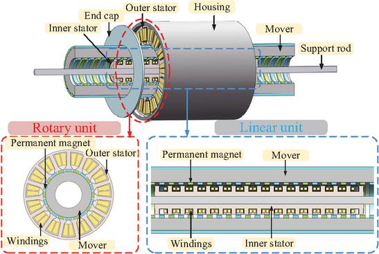
Figure 1 Structure of the MPMLRG.
Table 1 Key parameters of the MPMLRG
| Parameter | Symbol | Value | |
| RGU | Outer diameter of outer stator | 150 mm | |
| Inner diameter of outer stator | 86 mm | ||
| Outer diameter of mover | 84 mm | ||
| Length of outer stator | 150 mm | ||
| Outer stator pole height | 22.5 mm | ||
| Outer stator yoke height | 3.7 mm | ||
| Air-gap thickness | 1 mm | ||
| Rated speed | 300 rpm | ||
| Number of turns per phase | |||
| Resistance of phase winding | |||
| LGU | Outer diameter of inner stator | 36 mm | |
| Inner diameter of inner stator | 10 mm | ||
| Inner diameter of mover | 39 mm | ||
| Length of inner stator | 262.5 mm | ||
| Inner stator pole height | 6 mm | ||
| Inner stator yoke height | 22 mm | ||
| Air-gap thickness | 1.5 mm | ||
| Rated speed | 1 m/s | ||
| Number of turns per phase | |||
| Resistance of phase winding |
Table 2 Material thermal data
| Model Region | Thermal Conductivity (W/(mK)) | Density (kg/m3) | Specific Heat (J/(kgK)) | ||
| Direction X | Direction Y | Direction Z | |||
| Stator slots of RGU | 0.23 | 0.23 | 276.06 | 5514.34 | 405.9 |
| Stator slots of LGU | 273.05 | 273.05 | 0.19 | 6411.22 | 403 |
| Permanent magnet | 9 | 9 | 7 | 7500 | 400 |
| Lamina ted core | 35 | 35 | 2 | 7650 | 450 |
| Support rod | 47 | 47 | 47 | 7850 | 470 |
| Housin g | 90 | 90 | 90 | 2700 | 900 |
| End cap | 0.3 | 0.3 | 0.3 | 920 | 1900 |
| Note: X, Y, and Z denote the local radial, circumferential, and axial directions, respectively. | |||||
2.2 Materials
The material properties of the MPMLRG significantly affect both electromagnetic and thermal behaviors. The permanent magnets are N48, and the stator and mover cores are made of laminated silicon steel 50W470. Both the RGU and LGU stator cores employ axially laminated silicon steel sheets. Although axial lamination may not be optimal for all magnetic flux paths in tubular linear machines, it is adopted in this study, and its influence on the thermal model is reflected through the anisotropic thermal conductivities assigned to the laminated cores. A discussion on the influence of lamination orientation in tubular linear machines can be found in [20].
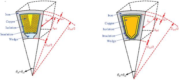
Figure 2 Dimensions of the RGU stator slot: (a) individual slot geometry and (b) equivalent slot model.
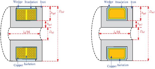
Figure 3 Dimensions of the LGU stator slot: (a) individual slot geometry and (b) equivalent slot model.
Thermal modeling of the stator slots is nontrivial due to the composite winding region. Therefore, an equivalent thermal conductivity approach is adopted to represent the anisotropic heat conduction of the slot region. As shown in Figs. 2 and 3, the slot region is homogenized by combining the copper conductors, insulation, impregnation materials, wedges, and slot fillers into an equivalent anisotropic medium. The homogenized slot regions correspond to the equivalent stator-slot materials used in the thermal model. Owing to the different winding configurations, the RGU and LGU stator slots exhibit different principal thermal conductivity directions. The RGU winding is mainly arranged along the axial direction, whereas the annular winding of the LGU provides higher equivalent thermal conductivity within the plane of the winding layers. The equivalent conductivities are determined from the slot geometry, material fractions, and a standard series model. Consequently, the detailed material distribution inside each slot is represented by an equivalent homogeneous anisotropic region in the thermal model.
The thermal conductivities, densities, and specific heats used in the transient thermal analysis are summarized in Table 2.
3 LOSS MODELS
Accurate loss estimation is essential for thermal analysis because the losses act as heat sources. In this section, the losses of the MPMLRG under different operating conditions are analyzed using both FEM and analytical methods.
3.1 Copper loss
The MPMLRG operates at relatively low electrical frequencies (50 Hz for RGU and 41.67 Hz for LGU under rated conditions). Therefore, only DC resistance is considered, and copper loss is calculated as follows:
| (1) |
where is phase number, and are phase current (RMS) and phase resistance, respectively.
3.2 Core loss
According to the Steinmetz formula, the core loss can be expressed as [21]:
| (2) | ||
| (3) |
where and represent the hysteresis and eddy-current losses (W/kg), is the volume of the laminated iron core, is the amplitude of the nth harmonic flux density, is the total number of harmonics, denotes the fundamental electrical angular frequency (rad/s), the angular frequency of the nth harmonic is , and and are the hysteresis and eddy-current loss coefficients. In this study, and , which were obtained by nonlinear fitting of the loss data for 50W470 silicon steel.
3.3 Permanent magnet eddy current loss
The magnetic field in the MPMLRG can be divided into two components: the main field, generated by the mover-mounted permanent magnets, which rotates and translates synchronously with the mover and is therefore approximately stationary in the permanent magnet reference frame, contributing negligibly to the permanent magnet eddy-current loss; and the harmonic field, which lacks such synchronism and consequently induces electromotive force (EMF), eddy currents, and associated losses in the permanent magnets of both the RGU and the LGU. The eddy-current loss in the mover-permanent magnets, resulting from harmonic components of the air-gap magnetic field, is quantified by (4) over one alternating-magnetization period, as described in [22]:
| (4) |
where denotes the rotor eddy current loss [W], is the current density in each element , is the element area is the mover axial length [m], is the conductivity of the eddy current zone [S/m], and is the time corresponding to an alternating magnetization period in each element.
3.4 Heat generation
To evaluate the thermal behavior of the 2-DOF MPMLRG under helical motion, five representative operating cases are considered by simultaneously varying the rotational and translational speeds of the mover around the rated condition. The volumetric heat generation rates of major components are given in Table 3. Case 1 corresponds to the rated speeds of 300 rpm and 1.0 m/s, while in Cases 2–5 the rotational speed is increased in steps of 50 rpm and the linear speed in steps of 0.2 m/s. For all cases, the RGU and LGU load resistances are set to 5 and 1 , respectively. The resulting losses are converted into volumetric heat generation rates and applied as heat sources in the LPTN and FEA models.
Table 3 Volumetric heat generation rates of major components
| Motor Part | Heat Generation (W/m3) | ||||
| Case 1 | Case 2 | Case 3 | Case 4 | Case 5 | |
| Stator of RGU | 10513.53 | 12085.01 | 13861.75 | 15418.34 | 16588.97 |
| Winding of RGU | 165496.42 | 201620.49 | 241031.21 | 266156.82 | 290465.48 |
| PM of RGU | 2437.40 | 3335.63 | 4595.64 | 5772.04 | 6974.32 |
| Mover | 42.49 | 59.29 | 80.92 | 100.64 | 108.76 |
| PM of LGU | 670.24 | 961.91 | 1028.13 | 1060.38 | 1066.33 |
| Stator of LGU | 207225.95 | 302137.07 | 415043.91 | 560906.21 | 692365.80 |
| Winding of LGU | 39518.48 | 55733.89 | 75263.31 | 99711.47 | 124060.68 |
4 LUMPED PARAMETER THERMAL NETWORK MODEL
To facilitate numerical analysis, the motor structure is discretized into thermal nodes based on material properties and geometry. Thermal resistances between nodes are calculated according to their spatial arrangements and heat pathways. Losses from components are proportionally distributed to corresponding nodes. Steady-state and transient heat transfer equations are formulated and solved using MATLAB to obtain the temperature at each node.
To simplify the three-dimensional temperature field while maintaining sufficient accuracy, the following assumptions are adopted: (i) circumferential temperature symmetry is assumed; (ii) heat transfer is dominated by conduction, whereas radiation and skin effects are neglected; and (iii) the short end windings of the RGU are ignored.
Based on these assumptions, the machine is partitioned into representative thermal regions, each modeled as a thermal node located at its geometric center. Heat exchange between nodes is represented by thermal resistances. The resulting LPTN is illustrated in Fig. 4, where nodes are assigned to the stator yoke, stator slots, stator teeth, permanent magnets, mover yoke, air gaps, support rod, housing, end caps, and internal air regions of both the RGU and LGU.
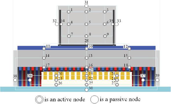
Figure 4 Key thermal nodes of the MPMLRG cross-section.
4.1 Steady-state and transient thermal network method
The steady-state thermal behavior of the motor is modeled by formulating a linear algebraic system derived from the nodal energy balance equations. In this framework, the motor is discretized into multiple thermal nodes, each corresponding to a specific structural region. The inter-nodal heat conduction is captured by a global thermal conductance matrix [23], constructed as the inverse of the thermal resistances between physically connected nodes. The internal heat generation due to electromagnetic losses is represented by a source vector , uniformly distributed across the corresponding nodes. The steady-state temperature distribution is then obtained by solving:
| (5) |
where denotes the vector of steady-state nodal temperatures. Owing to the localized heat-transfer paths, is symmetric and sparse, and its conductance topology (Fig. 5) provides an efficient representation of the steady-state thermal behavior of the MPMLRG.
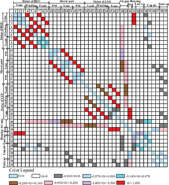
Figure 5 Thermal conductance network between different components.
The transient thermal model describes the time-dependent temperature evolution by incorporating both internodal thermal conductance and thermal capacitance, the latter determined by material density, specific heat, and volume. The resulting dynamic thermal behavior is governed by the following first-order differential equation:
| (6) |
where is the diagonal thermal capacitance matrix, is the thermal conductance matrix, represents the instantaneous nodal temperature vector, and denotes the time-dependent heat generation vector. This formulation captures both heat diffusion across components and energy accumulation due to thermal inertia.
4.2 Thermal resistance and thermal capacitance
Thermal resistance in electric machines can be categorized into two types: conduction thermal resistance and convection thermal resistance. Conduction thermal resistance occurs within the solid components of the machine. As shown in Fig. 6, based on the fundamental law of heat conduction, the thermal conduction resistances of the two models are derived as follows [24].
The thermal resistance of the flat plate conduction model is given by:
| (7) |
The thermal resistance of the cylindrical conduction model is given by:
| (8) |
where is the length along the direction of heat flow [m], denotes the thermal conductivity of the material , and represents the cross-sectional area for heat conduction .
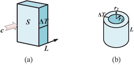
Figure 6 Two types of conduction resistance models.
Thermal capacitance can be given as:
| (9) |
where denotes body mass and is specific heat capacity.
As shown in Fig. 7, the nodes denote different components of the MPMLRG interconnected along the actual heat-transfer paths to establish the simplified LPTN. Based on well-established lumped-parameter thermal modeling theory, the thermal resistances and thermal capacitances of each node are determined from the corresponding geometry and material properties, and only the general formulation is presented here for conciseness.
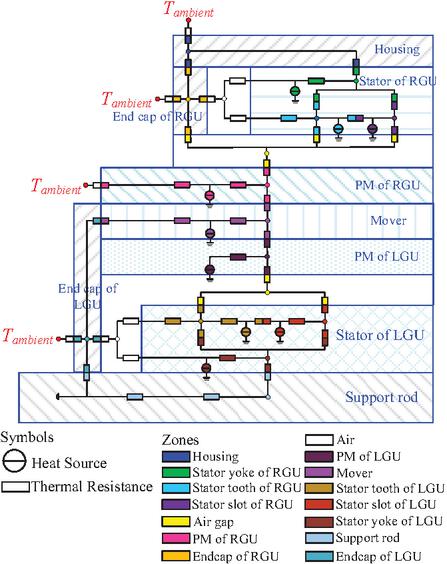
Figure 7 Simplified LPTN for the MPMLRG.
4.3 Air gap heat transfer coefficient
The convective heat transfer within the air gap is evaluated through the following approach. For unified expression, the outer and inner boundaries of each cylindrical air gap are denoted as and . Initially, the air-gap Taylor number , defined using the mean radius , and the geometry factor [25] are calculated by:
| (10) |
and
| (11) |
where denotes the mover’s angular velocity and is the kinematic viscosity of air. The structural parameter is given by:
| (12) |
Subsequently, the air-gap Nusselt number is obtained as a function of , as shown in (13). When , thermal convection is negligible, and heat transfer across the air gap is dominated by conduction. For , the flow in the gap becomes laminar with vortex formation, while for , turbulent flow governs the convective heat exchange.
| (13) |
Based on the calculated Nusselt number, the air-gap convective heat transfer coefficient can be derived accordingly as:
| (14) |
Referring to (11) and the dimensional parameters listed in Table 1, the geometry factor of outer and inner airgap for the analyzed MPMLRG at rated speed is calculated to be and , respectively. The air’s kinematic viscosity is taken as and the air-gap thermal conductivity is . According to (10), the corresponding air-gap Taylor numbers under the operating condition of a mover speed of are calculated as: .
Since , and , heat transfer within the air gap is dominated by thermal conduction rather than convection. As a result, the air-gap convective heat transfer coefficient is calculated as: . In this regime, , and the resulting represents the conduction-dominated equivalent heat-transfer coefficient across the air gap (i.e., ). It should be noted that this formulation represents an equivalent heat-transfer coefficient across the air gap, which is commonly adopted in electrical machine thermal modeling when the air flow remains weak.
By substituting the thresholds and , and into (13), the corresponding boundary mover speeds for the RGU and LGU are determined to be 916, 2223, and 70308 rpm, and 793, 1923, and 60828 rpm, respectively, which indicates that the analyzed operating range is well within the conduction-dominated regime.
However, in the case of MPMLRG, the mover undergoes both rotational and translational motions simultaneously, resulting in a helical trajectory. To more accurately represent the convective flow driven by such compound motion, an effective air-gap velocity can be defined as:
| (15) |
where is the tangential velocity and is the linear velocity of the mover. According to forced convection theory, the convective heat transfer coefficient is proportional to velocity raised to a power , typically for turbulent forced convection of gases:
| (16) |
Consequently, the original convective coefficient can be corrected as:
| (17) |
This correction allows the model to incorporate the enhancement in heat transfer caused by the superimposed translational motion of the mover.
To further explore the influence of motion parameters on air-gap heat transfer performance, the same five operating conditions (Cases 1–5) introduced in section III part D are adopted. These include the rated operating condition (Case 1) and four additional cases with increased rotational and linear speeds. In each case, the corresponding Taylor number and Nusselt number are calculated, and the convective heat transfer coefficients of both the air gaps of RGU and LGU are evaluated accordingly.
As shown in Fig. 8, the convective heat transfer coefficients of both air gaps increase with speed due to enhanced forced convection.
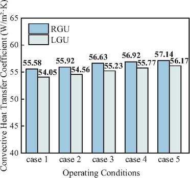
Figure 8 Air-gap convective heat transfer coefficients.
Due to the dual-stator configuration of the MPMLRG, the outer and inner stators have axial lengths of 150 mm and 262.5 mm, respectively, whereas the mover spans a total of 400 mm. During operation, the mover undergoes a compound motion consisting of rotation and linear translation, resulting in a helical trajectory along the axial direction. Because of the mismatch in axial dimensions, not all portions of the mover surface are continuously enclosed by the stator cores. This partial air-gap exposure is illustrated schematically in Fig. 9, where the helical motion path and bidirectional travel of the mover are shown. Specifically, only a segment of the mover’s outer surface forms an active air gap with the outer stator, while the rest is exposed to ambient air. A similar condition applies to the inner air gap.
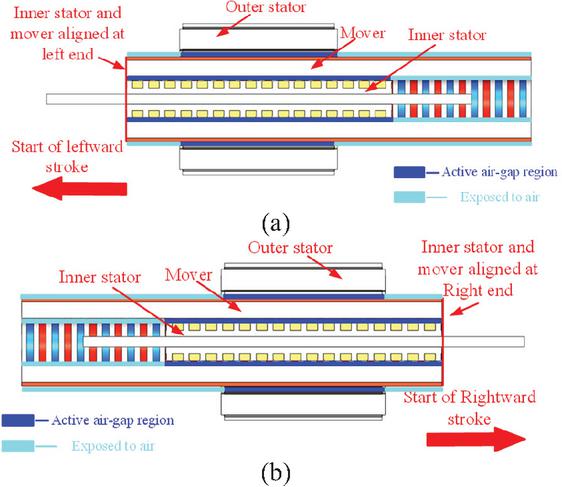
Figure 9 Relative positions between the mover and stator during reciprocating motion: (a) left stroke limit and (b) right stroke limit.
To accurately represent this intermittent contact during motion, the convective heat transfer coefficients of the inner and outer air gaps are modified using a time-weighted approach, expressed as:
| (18) |
where is the effective contact ratio determined by the axial coverage of the stator relative to the mover and is the natural convection heat transfer coefficient for the exposed surfaces. This method ensures the thermal model reflects realistic boundary conditions during coupled motion.
5 LPTN MODEL SOLVING AND 3-D FEA VERIFICATION
The proposed LPTN model predicts the average temperature of lumped components rather than detailed spatial distributions. Therefore, a 3-D thermal FEA model is established to obtain the temperature field and to validate the accuracy of the LPTN predictions. The heat transfer coefficients used in the FEA are consistent with those derived from the thermal network modeling in section IV.
5.1 Establishment of finite element model
The temperature distributions obtained from the 3-D thermal model implemented in ANSYS Workbench are shown in Fig. 10. The ambient temperature is set to 22∘C.
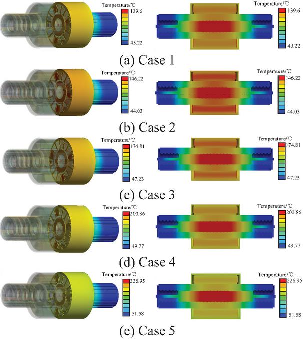
Figure 10 3-D temperature distribution and cross-section of MPMLRG @ five operating cases.
At the rated operating condition, thermal behaviors are observed in the RGU and LGU. In the RGU, the stator iron and windings exhibit the highest temperatures, whereas the mover and permanent magnets remain significantly cooler due to partial exposure to ambient air. Similarly, in the LGU, the stator and windings experience higher temperature rise, while the permanent magnets remain at relatively low temperatures. Although the LGU winding generates higher losses, its temperature is comparable to that of the RGU owing to the annular winding configuration, which enhances heat conduction to the stator core. However, the enclosure of the inner stator by the mover restricts heat dissipation, leading to a slightly higher temperature rise.
With increasing operating speed, the temperatures of both the RGU and LGU increase monotonically, indicating that natural convection alone is insufficient to offset the additional heat generation. At Case 5, severe thermal stress is observed, particularly in the stator windings, with the LGU inner winding becoming the most thermally critical component. In contrast, the mover and permanent magnets remain within a relatively safe temperature range.
It should be noted that these results are obtained under natural convection cooling only. At high operating speeds, excessive winding temperatures may compromise insulation reliability and reduce machine lifetime. Therefore, enhanced thermal management measures, such as winding impregnation or improved cooling strategies, are required for practical applications.
5.2 Steady-state LPTN
As shown in Fig. 11, the computing results of steady-state LPTN are compared with the results of FEA.
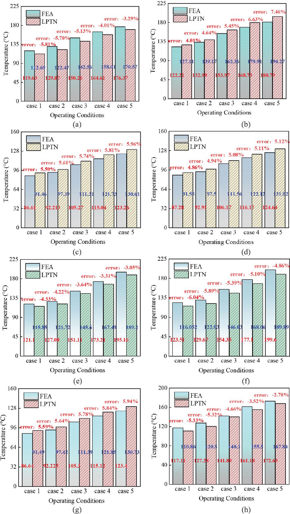
Figure 11 Comparison of steady-state temperature of major components in the MPMLRG predicted by the LPTN and 3-D FEA: (a) RGU stator, (b) RGU winding, (c) RGU PM, (d) LGU PM, (e) LGU stator, (f) LGU winding, (g) mover, and (h) housing.
It can be observed that the results of the LPTN calculation are in close agreement with those of the FEA, confirming the accuracy of the proposed LPTN model for the MPMLRG. The largest discrepancy is observed in the winding of the RGU, which is mainly attributed to the geometric simplifications adopted in the LPTN model. Nevertheless, the overall agreement demonstrates that the proposed model can provide reliable temperature prediction for engineering applications.
6 Transient LPTN
As shown in Fig. 12, the computing results of transient LPTN are compared with the results of FEA.
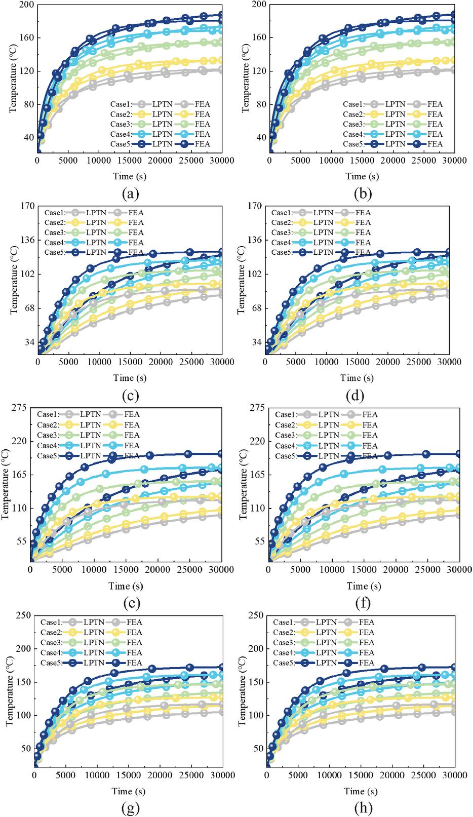
Figure 12 Comparison of transient temperature of major components in the MPMLRG predicted by the LPTN and 3-D FEA: (a) RGU stator, (b) RGU winding, (c) RGU PM, (d) LGU PM, (e) LGU stator, (f) LGU winding, (g) mover, and (h) housing.
It can be observed that the final steady-state results of both methods are in good agreement; however, the temperature predicted by the LPTN reaches steady-state more slowly than that of the FEA. This discrepancy mainly arises from the intrinsic modeling assumptions of the LPTN. In the LPTN, multiple local heat-transfer paths are represented by equivalent thermal resistances and thermal capacitances. The spatial averaging smooths local temperature gradients and increases the effective thermal inertia of each thermal node, thereby slowing the predicted heat diffusion process. In contrast, the FEA explicitly resolves the distributed temperature field and local heattransfer paths, allowing local regions to respond more rapidly to thermal excitation. Consequently, the LPTN exhibits a slightly slower transient response while maintaining good agreement with the FEA under steady-state conditions. This characteristic does not affect its suitability for thermal design and steady-state temperature prediction.
7 CONCLUSION
A lumped-parameter thermal network model for the dual-stator MPMLRG was developed and validated against 3-D FEA. Both methods reveal that stator windings are the most thermally critical components, with the inner stator winding of the LGU exhibiting the highest temperature due to limited heat dissipation. The LPTN demonstrates good agreement with FEA in steady-state prediction, though it slightly underestimates transient dynamics owing to simplified thermal inertia representation. At high operating speeds, winding overheating becomes significant, underscoring the necessity of enhanced cooling strategies. Future work will integrate advanced cooling methods and couple the LPTN with dynamic electromagnetic loss models to support reliability assessment and design optimization. Future work will include experimental validation on a prototype to further verify the proposed thermal model under practical operating conditions.
ACKNOWLEDGMENT
This work was supported by the National Natural Science Foundation of China (52577073), the Natural Science Foundation of Henan (252300421095), the China Postdoctoral Science Foundation (2026T190135, 2025M780487), and the Henan Province Key R&D and promotion projects (Scientific and Technological Breakthrough) (262102241045).
REFERENCES
[1] M. A. Mueller, J. Burchell, Y. C. Chong, O. Keysan, A. McDonald, M. Galbraith, and E. J. P. Echenique Subiabre, “Improving the thermal performance of rotary and linear air-cored permanent magnet machines for direct drive wind and wave energy applications,” IEEE Trans. Energy Convers., vol. 34, no. 2, pp. 773–781, June 2019.
[2] L. Xu, C. Zhang, and X. Zhu, “Decoupling control of a dual-stator linear and rotary permanent magnet generator for offshore joint wind and wave energy conversion system,” IET Electric Power Appl., vol. 4, no. 4, pp. 561–569, Apr. 2020.
[3] L. Szabó, “On the use of rotary-linear generators in floating hybrid wind and wave energy conversion systems,” in Proc. IEEE Int. Conf. Autom., Quality Testing, Robot. (AQTR), Cluj-Napoca, Romania, pp. 1–6, 2018.
[4] E. D. Stoutenburg and M. Z. Jacobson, “Reducing offshore transmission requirements by combining offshore wind and wave farms,” IEEE J. Ocean. Eng., vol. 36, no. 4, pp. 552–561, Oct. 2011.
[5] E. D. Stoutenburg and M. Z. Jacobson, “Reducing offshore transmission requirements by combining offshore wind and wave farms,” IEEE J. Ocean. Eng., vol. 36, no. 4, pp. 552–561, Oct. 2011.
[6] L. Szabó, “On the use of rotary-linear generators in floating hybrid wind and wave energy conversion systems,” in Proc. IEEE Int. Conf. Autom., Quality Testing, Robot, Cluj-Napoca, Romania, pp. 1–6, 2018.
[7] N. A. Bhuiyan and A. Mcdonald, “Optimization of offshore direct drive wind turbine generators with consideration of permanent magnet grade and temperature,” IEEE Trans. Energy Convers., vol. 34, no. 2, pp. 1105–1114, June 2019.
[8] X. Song, J. Zhao, J. Song, F. Dong, L. Xu, and J. Zhao, “Local demagnetization fault recognition of permanent magnet synchronous linear motor based on S-transform and PSO-LSSVM,” IEEE Trans. Power Electron., vol. 35, no. 8, pp. 7816–7825, Aug. 2020.
[9] L. Xu, X. Zhu, C. Zhang, L. Zhang, and L. Quan, “Power oriented design and optimization of dual-stator linear-rotary generator with Halbach PM array for ocean energy conversion,” IEEE Trans. Energy Convers., vol. 36, no. 4, pp. 3414–3426, Dec. 2021.
[10] F. Xing, W. Jian, and L. Ming, “Design and analysis of linear-rotary permanent magnet generator for wind-wave combined power generation system,” in Proc. 20th Int. Conf. Electr. Mach. Syst. (ICEMS), Sydney, NSW, Australia, pp. 1–6, Aug. 2017.
[11] S. Nateg, O. Wallmark, M. Leksell, and S. Zhao, “Thermal analysis of a PMaSRM using partial FEA and lumped parameter modeling,” IEEE Trans. Energy Convers., vol. 27, no. 2, pp. 477–488, June 2012.
[12] A. B. Nachouane, A. Abdelli, G. Friedrich, and S. Vivier, “Numerical study of convective heat transfer in the end regions of a totally enclosed permanent magnet synchronous machine,” IEEE Trans. Ind. Appl., vol. 53, no. 4, pp. 3538–3547, July-Aug. 2017.
[13] J. Huang, Y. Xu, L. Xiao, L. Zhuo, G. Yu, and J. Zou, “Study of thermal field analysis methods of oil-filled motors,” IEEE Trans. Appl. Supercond., vol. 34, no. 8, pp. 1–5, Nov. 2024.
[14] J. Bao, B. L. J. Gysen, K. Boynov, J. J. H. Paulides, and E. A. Lomonova, “Torque ripple reduction for 12-stator/10-rotor-pole variable flux reluctance machines by rotor skewing or rotor teeth non-uniformity,” IEEE Trans. Magn., vol. 53, no. 11, pp. 1–5, Nov. 2017.
[15] L. Mo, T. Zhang, and Q. Lu, “Thermal analysis of a flux-switching permanent-magnet double-rotor machine with a 3-D thermal network model,” IEEE Trans. Appl. Supercond., vol. 29, no. 2, pp. 1–5, Mar. 2019.
[16] X. Jiang, Y. Zhang, S. Jin, F. Zhang, and C. Gerada, “A novel thermal network model used for temperature calculation and analysis on brushless doubly-fed generator with winding encapsulating structure,” IEEE Trans. Ind. Appl., vol. 55, no. 2, pp. 1473–1483, Mar.-Apr. 2019.
[17] J. Si, S. Zhao, H. Feng, Y. Hu, and W. Cao, “Analysis of temperature field for a surface-mounted and interior permanent magnet synchronous motor adopting magnetic-thermal coupling method,” CES Trans. Electr. Mach. Syst., vol. 2, no. 1, pp. 166–174, Mar. 2018.
[18] R. Camilleri, D. A. Howey, and M. D. McCulloch, “Predicting the temperature and flow distribution in a direct oil-cooled electrical machine with segmented stator,” IEEE Trans. Ind. Electron., vol. 63, no. 1, pp. 82–91, Jan. 2016.
[19] V. Ruuskanen, J. Nerg, M. Niemelä, J. Pyrhönen, and H. Polinder, “Effect of radial cooling ducts on the electromagnetic performance of the permanent magnet synchronous generators with double radial forced air cooling for direct-driven wind turbines,” IEEE Trans. Magn., vol. 49, no. 6, pp. 2974–2981, June 2013.
[20] G. Cipriani, M. Corpora, V. Di Dio, A. Musolino, R. Rizzo, and L. Sani, “A comparison among different kinds of stator lamination in tubular linear machines,” Progress in Electromagnetics Research M, vol. 50, pp. 95–104, 2016.
[21] A. Belahcen and A. Arkkio, “Comprehensive dynamic loss model of electrical steel applied to FE simulation of electrical machines,” IEEE Trans. Magn., vol. 44, no. 6, pp. 886–889, June 2008.
[22] X. Zhang, H. Zhang, W. Li, C. Gerada, D. Gerada, and J. Li, “Thermal barrier for high-voltage permanent magnet synchronous motor with aircooling hybrid ventilation systems,” in Proc. 22nd Int. Conf. Elect. Mach. Syst., Harbin, China, pp. 1–4, 2019.
[23] Q. Chen, D. Liang, L. Gao, Q. Wang, and Y. Liu, “Hierarchical thermal network analysis of axial-flux permanent-magnet synchronous machine for electric motorcycle,” IET Electr. Power App., vol. 12, no. 6, pp. 859–866, July 2018.
[24] J. Pyrhönen, T. Jokinen, and V. Hrabovcová, Design of Rotating Electrical Machines. Chichester: John Wiley & Sons, 2008.
[25] D. A. Howey, P. R. N. Childs, and A. S. Holmes, “Air-gap convection in rotating electrical machines,” IEEE Trans. Ind. Electron., vol. 59, no. 3, pp. 1367–1375, Mar. 2012.
BIOGRAPHIES

Chenxi Li was born in Sichuan, China, in 2001. She received the B.S. degree in electrical engineering and automation from Henan University of Technology, Zhengzhou, in 2023. She is currently working toward the M.S. degree in the School of Electrical Engineering at Zhengzhou University, Zhengzhou. Her research interests include renewable energy generation technologies and thermal analysis of two-degree-of-freedom motors.

Rui Nie received the B.S. degree in electrical engineering from Henan Polytechnic University, Jiaozuo, China, in 2015, and the Ph.D. degree in electrical engineering from China University of Mining and Technology, Xuzhou, in 2020. She is currently a Research Fellow at Zhengzhou research interests include two-degree-of-freedom machines, linear motor and renewable energy generation technologies.

Shuai Xu received the B.S. degree in electrical engineering and automation and the Ph.D. degree in electrical engineering from China University of Mining and Technology, Xuzhou, China, in 2014 and 2019, respectively. Since 2021, he has been an Associate Professor at Zhengzhou University. His research interests include motor design and control.

Yanqi Wei received the Ph.D. degree in electrical engineering from Zhengzhou University, Zhengzhou, China, in 2024. He is currently a Postdoctoral Researcher with the School of Electrical and Information Zhengzhou University. His research interests include the design, analysis, axial-flux permanent-magnet motors.

Peixin Wang received the B.S. and M.S. degrees from Henan Polytechnic University, Jiaozuo, China, in 2016 and 2018, respectively, and the Ph.D. degree from Southeast University, Nanjing, in 2022. He is currently a Lecturer at Zhengzhou University. His research interests include air-gap flux modulation theory and the design and analysis of special machines.

Jikai Si received the B.S. degree in electrical engineering and automation from Jiaozuo Institute of Technology, Jiaozuo, China, in 1998, the M.S. degree from Henan Polytechnic University, Jiaozuo, in 2005, and the electrical engineering from China University of Mining and Technology, He is currently a Distinguished Professor at Zhengzhou University. His include the theory and control of special motors.
ACES JOURNAL, Vol. 41, No. 6, 524–535
DOI: 10.13052/2026.ACES.J.410604
© 2026 River Publishers