High Efficiency, Low-Power RF Energy Harvesting Tri-Band Rectenna for Mid-Band 5G and Wi-Fi 6E Applications
Abdelkrim Belhedri1, Boualem Mekimah1, Boualem Hammache2, Tayeb A. Denidni3, Abderraouf Messai2, and Mohammed Boulesbaa1
1Department of Electronics and Telecommunications University Kasdi Merbah, Ouargla, 30000 rue de Ghardaia B.P. 511, Algeria
belhedri.abdelkrim@univ-ouragla.dz, mekimah.boualem@univ-ouragla.dz, boulesbaa.mohammed@univ-ouragla.dz
2Department of Electronics University Freres Mentouri, Constantine 1, Constantine 25000, Algeria
boualem_hammache@hotmail.fr, r_messai@yahoo.fr
3Institut National de la Recherche Scientifique (INRS) Université du Québec, Montréal, 800 rue de la Gauchetière QC H5A 1K6, Canada
Tayeb.Denidni@inrs.ca
Submitted On: January 31, 2026
Accepted On: May 17, 2026
ABSTRACT
In this paper, a new tri-band rectenna is presented for radio frequency energy harvesting (RFEH) deployment. The proposed RFEH system integrates two primary components: an antenna and a rectifier. First, the antenna consists of a CPW-fed circularly-shaped patch incorporating three slots. Each slot is strategically introduced to reject a specific band. Second, the rectifier circuit is structured to ensure an efficient RF-to-DC conversion over three bands. High efficiency peaks are achieved at 78%, 76%, and 60% respectively at 3 GHz, 4 GHz, and 6.5 GHz, under 5 dBm input power, with overall efficiency average exceeding 71%. Peak DC output voltages of 2.52 V, 2.47 V, and 2.20 V are obtained at the same frequencies under the same conditions. The results confirm that the proposed rectenna effectively spans both the 5G mid-band and Wi-Fi 6E band, enabling the simultaneous and reliable powering of low-power devices. Furthermore, the antenna exhibits high frequency repeatability, achieved through the independent tuning of each band via strategically integrated slots.
Keywords: Power conversion efficiency (PCE), radio frequency energy harvesting (RFEH), rectifier circuit, Schottky diode, tri-band rectenna..
1 INTRODUCTION
Radio frequency energy harvesting (RFEH) has emerged as a vital solution for empowering low-power wireless electronic devices, including sensors, remote controls, RFID tags, Internet of Things (IoTs), and biotelemetry systems. By harnessing ambient RF signals, RFEH enables sustainable, battery-free operation, reducing maintenance costs and supporting seamless deployment of next-generation smart and connected technologies.
In the literature, many works on RFEH, have been proposed with the aim of improving the power conversion efficiency (PCE), and optimizing the utilization of harvested energy in both single-band and multi-band configurations [1, 2, 3, 4, 5, 6, 7, 8, 9, 10, 11, 12, 13, 14, 15, 16, 17]. Actually, single-band operation and low PCE of RFEH systems significantly restrict their ability to harvest enough energy. Therefore, a multiband rectenna is a pivotal solution in wireless RFEH, attracting considerable attention for their capability to harvest radio frequency (RF) energy across multiple bands simultaneously [1, 3, 4, 8, 9, 10]. Such a rectenna significantly outperforms traditional designs, enabling higher cumulative power generation. It also offers improved adaptability to diverse RF environments, and greater potential for powering next generation low-power electronic devices and IoT systems. However, the increase in the number of operating bands decreases substantially the PCE, posing therefore a huge issue in multi-band rectenna scenarios. In such architectures, the PCE obtained per band is typically lower than that of single-band rectennas, which results in an overall PCE average lower than the values reported for single-band counterparts. This behavior is attributed to the power split across multiple paths, which leads to an accumulation of ohmic and mismatch losses associated with each path. For instance, the single-band rectennas in [2, 6, 7] exhibit PCE peaks of 61% at an input power of dBm, 67.3% at dBm, and 67.16% at dBm, respectively. Conversely, the reduced PCE observed in multi-band rectennas [1, 3, 8, 9] remains a significant challenge in the field. According to the work in [1], a tri-band rectenna shows a relatively low PCE average of three bands of about 28.8% at dBm. Another contribution in [3] shows PCE of dual-band rectenna of 54.3% at 2.4 GHz and 52.7% at 5.8 GHz under input power of dBm, resulting in a PCE average of 53.5%. Also, a dual-band rectenna in [8] shows PCE peaks of 54% at 2.4 GHz and 44.4% at 5.8 GHz under 14 dBm input power, which yields a PCE average of 49.2%. In [9], a dual band rectenna offers peak conversion efficiencies of 61% at 1.75 GHz and 72% at 2.45 GHz with an input power of 0 dBm, giving a PCE average of 66.5%.
Among the rectennas reported in the literature, the proposed design combines high efficiency with multi-band capability, achieving a greater PCE average through the appropriate selection of the rectifier topology and the careful optimization of the matching network. Additionally, the incorporation of slot technique in the antenna geometry yields efficient frequency tuning, achieved simply by adjusting the length of each slot, offering precise and repeatable frequency. The proposed rectenna is designed exclusively to cover the standard 802.11ax [18], which is developed for unlicensed operations of the 5G and extended Wi-Fi 6E band of 5.925–7.125 GHz. This last offers high throughput, higher reliability, and low-latency [19]. Within its operating band, the proposed rectenna exhibits high capability for integration into advanced technologies.
2 ANTENNA DESIGN
The proposed antenna, as depicted in Fig. 1, is designed using a rogers RO4003C substrate of a permittivity of 3.38, a loss tangent of 0.0027, and a height of 1.524 mm. A CPW-fed circularly-shaped patch antenna is proposed including three slots within the feeding line and radiating element to reject three unwanted bands. The CST Microwave studio suite simulator tool version 2024 [20] is used for designing the antenna.
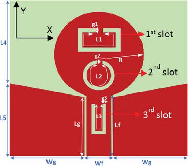
Figure 1 Proposed CPW-fed circularly-shaped antenna. L129.6, L216, L312.4, L421, L515, Lf13.13, Lg12.75, Wg17.10, R10, Wf3.8, g10.5, g20.72, g30.5 (all dimensions in mm).
Figure 2 portrays the reflection coefficient magnitude in dB against frequency in GHz of various configurations including: no slot, one slot, two slots and three slots. The final optimized configuration corresponds to the design incorporating two C-shaped slots and one U-shaped slot. In this design, the surface current is concentrated around the extremity of each slot, creating an impedance mismatch that stops the radiation at the associated frequency. The guided wavelength of the C-shaped slot is given as
| (1) |
where is the free-space wavelength and is the effective permittivity. The length of each slot, denoted , is around , which gives high capability for frequency shifting. Indeed, the notched frequency, denoted , is given as [21]
| (2) |
In the case of the U-shaped slot, the notched frequency is given as [22]
| (3) |
where and are the length and the width of the U-shaped slot respectively.
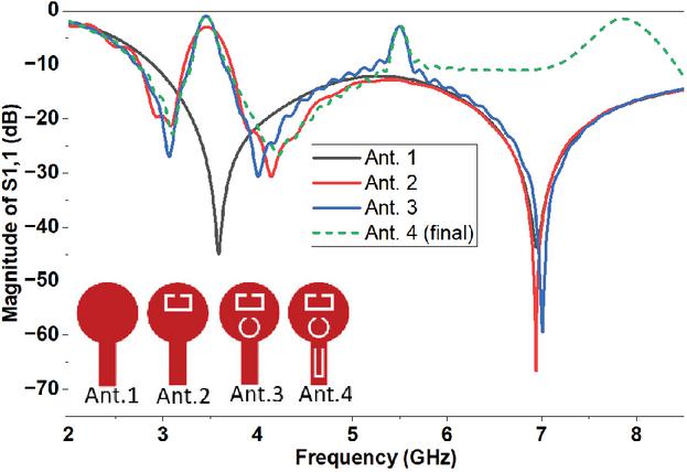
Figure 2 Magnitude of in dB against frequency in GHz of proposed configurations.
Figure 3 illustrates the realized gain (in dBi) as a function of frequency (in GHz) for several design configurations. These configurations include the baseline design with no slot, as well as designs incorporating one slot, two slots, and three slots. The final configuration represents the three-slot design, which exhibits a deliberate reduction in gain at the three rejected frequency bands.
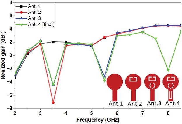
Figure 3 Realized gain in dBi against frequency in GHz of proposed configurations.
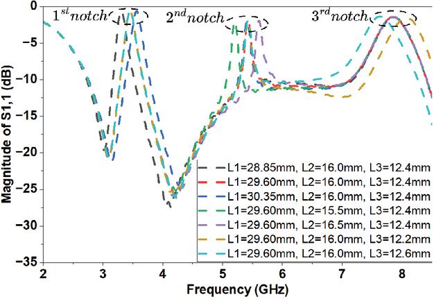
Figure 4 Slot length optimization, including L1, L2, and L3.
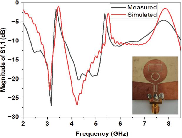
Figure 5 Magnitude of in dB against frequency in GHz of proposed antenna.
Figure 4 demonstrates the effect of slot length on the reflection coefficient, where each slot length is varied across three values, as indicated in the figure legend. The increase in slot length decreases the frequency notch as expected, which is consistent with the behavior predicted by equations (2) and (3).
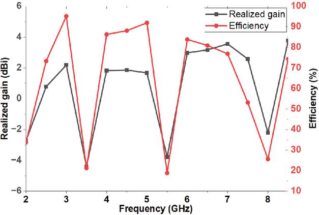
Figure 6 Realized gain (in dBi)/efficiency (in %) against frequency (in GHz) of the proposed antenna.
In Fig. 5, the reflection coefficient magnitude (in dB) is plotted against frequency (in GHz) for both simulation and measurement results. The plot demonstrates excellent impedance matching across the operating bands, with strong agreement between measured and simulated results. A slight discrepancy is observed due to the influence of the SMA connector.
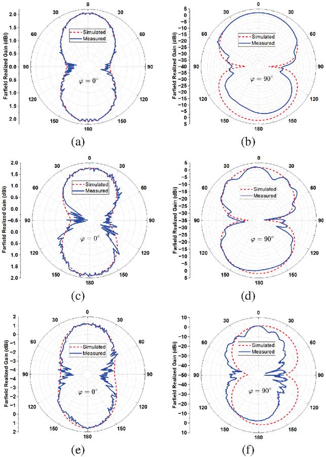
Figure 7 Radiation patterns of proposed antenna at (a,b) 3 GHz, (c,d) 4 GHz, and (e,f) 6.5 GHz.
The Agilent 8722ES network analyzer is used in measuring the reflection coefficient. The calibration is done by applying short, open, load, and through (SOLT) standards. Figure 6 presents both the realized gain (in dBi) and efficiency (in %) as a function of frequency (in GHz) for the optimized configuration. This latter corresponds to the three-slot design, which demonstrates significant reduction in both gain and efficiency at the three rejected frequency bands. Across the operating bands, the antenna maintains excellent radiation efficiency, reaching its maximum value of 95% at 3 GHz, with adequate gain.
Figure 7 shows the radiation patterns of the proposed antenna at three operating frequencies of 3 GHz, 4 GHz, and 6.5 GHz. The radiation pattern is evaluated in both the E- and H-planes (XZ- and YZ-planes). The antenna exhibits stable bidirectional radiation at all frequencies with adequate values.
Figure 8 demonstrates the anechoic chamber where the proposed prototype is measured. The measurement distance between the probe and the antenna under test (AUT) is 1.524 m. The double-ridged horn antenna, model AH-118, is used as a probe with an input power of 300 Watts.
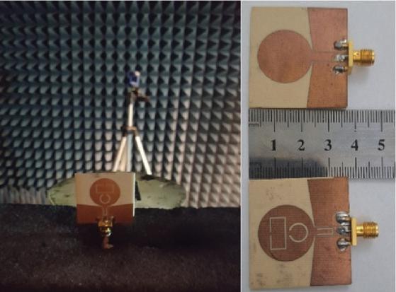
Figure 8 Anechoic chamber and proposed prototype.
3 A TRI-BAND RECTIFIER DESIGN
The rectifier section, as presented in Fig. 9, consists of four main blocks: a matching network that ensures proper impedance matching between the antenna and the rectifier circuit; the rectifier circuit, which converts the incoming RF signal into DC power; a DC-low pass filter that suppresses higher harmonics orders to maintain signal purity; and finally, the load, representing the device to be powered. The design of the rectifier is obtained by using advanced design system (ADS), simulator version 2020 [23].
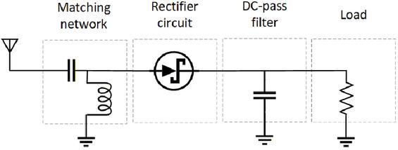
Figure 9 Rectifier synoptic scheme.
The PCE is the crucial parameter in RFEH, which measures the power ratio between DC and RF signals. It is expressed as [8]:
| (4) |
where is the DC power delivered to the load . is the input power injected at the rectifier input. Actually, the input power is linearly related to the rectenna gain by
| (5) |
where denotes the incident power density (in ), denotes the receiving antenna gain, and denotes the free-space wavelength. To obtain a highly sensitive rectenna, the antenna gain should be increased. The received power at the rectenna, denoted , is expressed as follows
| (6) |
where denotes the transmitted power (horn antenna power); and are the measured gains of the standard horn antenna and the rectenna under test, respectively. The parameter indicates the operating wavelength in free-space, and is the distance separating the two antennas. The equivalent circuit model of the Schottky diode is portrayed in Fig. 10 [24].
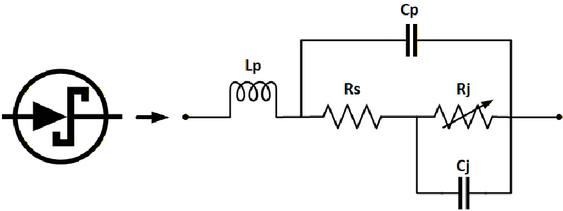
Figure 10 Schottky diode equivalent circuit model (ECM). SPICE parameters of the used SMS7621 series are: nH, pF, , pF, A, N=1.05, s, M 0.35, eV, XTI 2, , V, mA, and V.
The equivalent impedance of the Schottky diode denoted is given, according to its ECM in Fig. 10, by
| (7) |
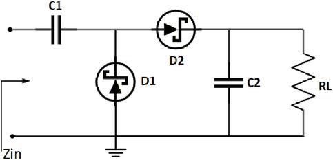
Figure 11 One stage Dickson voltage-doubler rectifier using Schottky diode SMS7621 series.
The input impedance of the voltage-doubler rectifier, denoted , is given according to Fig. 11 by
| (8) |
The input impedance of the rectifier, denoted , is plotted in Fig. 12 as a function of frequency for different input power levels. The input impedances of the rectifier, at input power of 5 dBm, are at 3 GHz, at 4 GHz, and at 6.5 GHz, respectively.
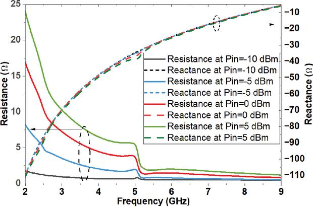
Figure 12 Rectifier input impedance in versus frequency in GHz by applying different values of input power .
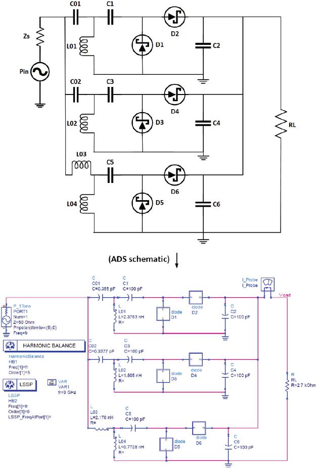
Figure 13 Proposed rectifier circuit for tri-band RF energy harvesting deployments using Schottky diode SMS7621, pF, .
Figure 13 displays the proposed tri-band energy harvesting rectifier circuit, including three L-section matching networks. Each circuit is calculated using the Smith Chart in Fig. 14. The calculated values for each band are applied and slightly tuned under =5 dBm input power to maximize the PCE, satisfying the matching condition . Each L-section circuit converts the 50 source impedance to the conjugate input impedance of each stage. The power delivered from the source encounters, in fact, three different paths, and the current flows through the path that is matched for the given frequency.
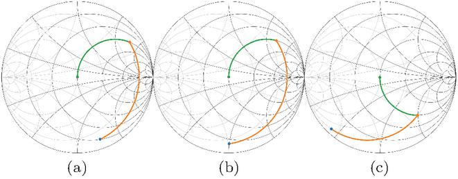
Figure 14 Impedance matching between the antenna and rectifier using Smith Chart at (a) 3 GHz, (b) 4 GHz, and (c) 6.5 GHz at dBm.
After the rectification process, the Schottky diode output is not purely DC. Instead, it contains a DC component along with the fundamental frequency and various higher-order harmonics. This spectral composition arises from the nonlinear behavior of the diode, which distorts the input signal. Therefore, a low-pass DC filter is crucial to suppress these harmonics [25]. The Schottky instantaneous diode current is expressed as follows
| (9) |
where is the saturation current, is the diode voltage, is the ideality factor, and is the thermal voltage.
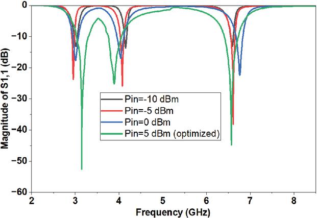
Figure 15 Magnitude of the reflection coefficient in dB versus frequency in GHz of the proposed rectifier circuit by applying different input power levels.
Figure 15 shows the magnitude of reflection coefficient in dB as a function of frequency in GHz for the proposed rectifier under input power levels of dBm, dBm, dBm, and dBm. The best impedance matching is obtained at dBm, which exhibits the lowest reflection coefficient across the three widest bandwidths centered at 3 GHz, 4 GHz, and 6.5 GHz.
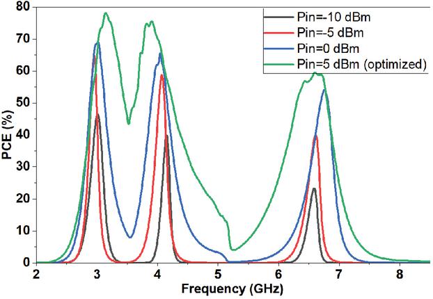
Figure 16 Power conversion efficiency (PCE) in % versus frequency in GHz for the proposed rectifier circuit by applying different input power levels.
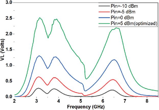
Figure 17 DC output voltage () in V against frequency in GHz for the proposed rectifier circuit.
Figures 16 and 17 present the PCE in % and the DC output voltage () in V as a function of frequency in GHz, for the proposed rectifier circuit at different input power levels, including dBm, dBm, dBm, and dBm. The highest values of PCE and DC output voltage are obtained by applying an input power level of dBm (3 mW). Reached peak values of the PCE are 78%, 76%, and 60% respectively at 3 GHz, 4 GHz, and 6.5 GHz. The corresponding peak DC output voltages of 2.52 V, 2.47 V, and 2.20 V are obtained at the same frequencies under 5 dBm input power.
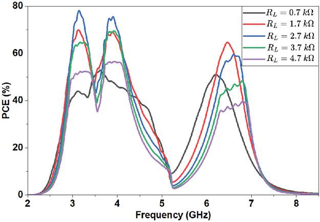
Figure 18 Power conversion efficiency () against frequency at different values of for the proposed rectifier circuit at 5 dBm.
Figure 18 displays the PCE against frequency for the proposed rectifier circuit at different values of including , , , , and . The optimized PCE is achieved with a load of , as expected, since this value is considered in the matching network.
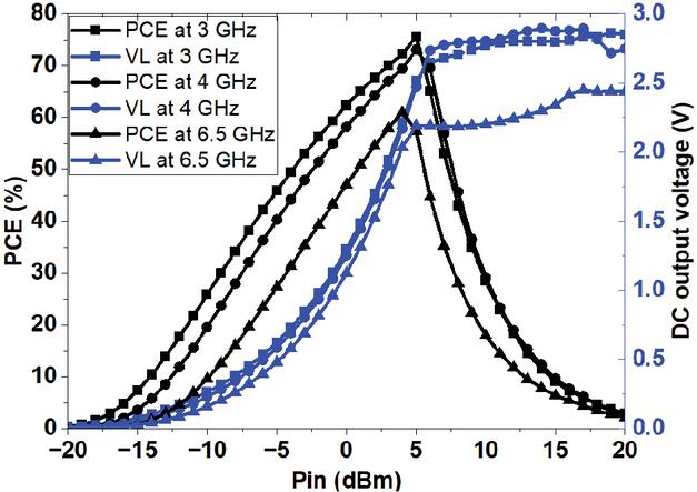
Figure 19 Power conversion efficiency (PCE) and DC output voltage () against input power () for the proposed rectifier circuit at 3 GHz, 4 GHz, and 6.5 GHz.
Figure 19 shows the PCE and DC output voltage () against input power () for the proposed rectifier circuit at 3 GHz, 4 GHz, and 6.5 GHz. The peak value of PCE is obtained at 5 dBm input power, while the DC output voltage continues to increase with input power. A merit factor is proposed here to perfectly characterize a multiband rectifier, referred to as the efficiency average, and given by
| (10) |
where is the total number of bands and is the band PCE.
Table 1 Performance comparison with the literature
| Ref. | Year | Number of | Max. PCE/ | Design |
| bands/ | PCE Ave. | Complexity | ||
| [1] | 2025 | 3/10 dBm | 36.8%/29% | High |
| [2] | 2025 | 1/18 dBm | 61%/NA | Medium |
| [3] | 2025 | 2/0 dBm | 54.3%/53.5% | High |
| [5] | 2023 | 1/17 dBm | 50%/NA | High |
| [6] | 2024 | 1/18 dBm | 67.3%/NA | Medium |
| [7] | 2024 | 1/5 dBm | 67.16%/NA | Low |
| [8] | 2025 | 2/14 dBm | 54%/44.4% | Medium |
| [9] | 2025 | 2/0 dBm | 61%/66.5% | Medium |
| [10] | 2025 | 3/20 dBm | 33.3%/23.3% | Medium |
| Proposed | 3/5 dBm | 78%/71% | Low | |
| Max. maximum, Ave. average, NA not applicable. | ||||
Table 1 compares the proposed rectenna to those recently reported in the literature. The proposed design demonstrates clear superiority in terms of the efficiency average, number of operating bands, and design simplicity. In contrast, most existing works [1, 2, 3, 5, 6, 7, 8, 9, 10] exhibit non-repeatable configurations and/or low efficiencies, restricting their ability in harvesting energy efficiently. The proposed rectifier shows a higher PCE of 78% with higher efficiency average of 71%, outperforming the majority of designs in the literature [1, 2, 3, 5, 6, 7, 8, 9, 10].
4 CONCLUSION
In this paper, a tri-band rectenna has been proposed and tailored for harvesting low-power RF energy from different bands. The power conversion efficiency (PCE) has peaked at 78%, 76%, and 60% respectively at 3 GHz, 4 GHz, and 6.5 GHz, yielding a PCE average exceeding 71% across the three bands. The proposed rectifier covers the mid-band 5G and Wi-Fi 6E deployments. A high simplicity of the proposed rectenna has been shown, which makes it highly repeatable in frequency with efficient AC-to-DC power conversion. Furthermore, incorporating the slot technique into the antenna design yields a highly tunable and repeatable frequency response. By combining high efficiency with multiband operation across independently tunable frequencies, the proposed rectenna delivers stable and sustained power output suitable for energy harvesting, particularly in low-power wireless devices.
REFERENCES
[1] J. Sang, L. Qian, X. Wang, M. Li, J. Wang, G. Shi, and Z. Zhu, “A triple-band and high-gain circularly polarized rectenna for radio-frequency energy harvesting applications,” IEEE Transactions on Antennas and Propagation, vol. 73, no. 8, pp. 5223–5238, 2025.
[2] J. Shi, C. Song, Y. He, C. Zhang, Y. Wang, Z. Zhang, J. Zhang, W. Li, and Y. Huang, “A high efficiency, simple-structure, compact wideband microwave energy harvester for wirelessly-powered IoT receivers,” IEEE Internet of Things Journal, vol. 12, no. 13, pp. 23510–23523, 2025.
[3] T. Ling, M. Li, H. Shao, J. Dong, and L. Qian, “A dual-band simple coplanar-structured rectifying metasurface for wireless energy harvesting,” IEEE Antennas and Wireless Propagation Letters, vol. 24, no. 7, pp. 1665–1669, 2025.
[4] G. Polaiah, “Rectifier integrated triple-band microwave absorber for efficient wireless power transmission,” Electromagnetics, vol. 45, no. 7, pp. 577–594, 2025.
[5] X. Liu, D. Zhang, Y. Li, and Z. Huang, “Super-broadband rectifier with wide-band resistance compression network and harmonic cycling for RF-harvesting,” Applied Computational Electromagnetics Society (ACES) Journal, vol. 38, no. 1, pp. 67–73, 2023.
[6] J. Liu and J. Y. Li, “A dual circularly polarized ultrawideband rectenna with high efficiency for wireless energy harvesting,” Applied Computational Electromagnetics Society (ACES) Journal, vol. 39, no. 3, p. 254, 2024.
[7] P. R. Meher, S. K. Mishra, and M. A. Halimi, “A low-profile compact broadband CP DRA for RF energy harvesting applications,” IETE Journal of Research, vol. 70, no. 5, pp. 4540–4548, 2024.
[8] J. Liu, B. X. Liu, and Z. F. Lu, “Design of a dual-band polarization reconfigurable rectenna for radio frequency energy harvesting,” IEEE Antennas and Wireless Propagation Letters, vol. 24, no. 6, pp. 1412–1416, 2025.
[9] H. W. Pan, P. F. Zhang, X. Xu, and X. H. Wang, “Compact dual-band patch rectennas impedance matching circuit eliminated for wireless energy harvesting,” Electromagnetics, vol. 45, no. 4, pp. 334–346, 2025.
[10] C.-H. Du, F. Cheng, Y. Yang, H. Zhu, and C. Gu, “Omnidirectional flexible tri-band rectenna with eliminated matching circuit for ambient RF energy harvesting,” IEEE Transactions on Microwave Theory and Techniques, vol. 73, no. 1, pp. 674–686, 2025.
[11] M. M. Fakharian, “A dual circular and linear polarized rectenna for RF energy harvesting at 0.9 and 1.8 GHz GSM bands,” Electromagnetics, vol. 41, no. 8, pp. 545–556, 2021.
[12] N. Chen and S. Yang, “A multi-band, multi-mode metasurface with only single-port for high-selective electromagnetic energy harvesting,” IEEE Transactions on Antennas and Propagation, vol. 73, no. 9, pp. 6437–6450, 2025.
[13] M. Labbaf, M. Bekrani, M. Fathollahi, and M. M. Taskhiri, “High-efficiency quad-band RF energy harvesting system with improved cross-coupled differential-drive rectifier,” Frequenz, vol. 79, no. 1-2, pp. 29–39, 2025.
[14] W. Zahra, A. Zerfaine, and T. Djerafi, “Dual-band impedance transformer using four-section with a wide and flexible frequency ratio,” Microwave and Optical Technology Letters, vol. 67, no. 8, p. e70309, 2025.
[15] M. T. Le, D. A. Pham, H. T. Vu, V. D. Ngo, and Q. C. Nguyen, “A novel dual-band ambient RF energy harvesting system for autonomous wireless sensor node application,” Applied Computational Electromagnetics Society (ACES) Journal, vol. 36, no. 10, pp. 1367–1375, 2021.
[16] X. Bai, J.-W. Zhang, L.-J. Xu, and B.-H. Zhao, “A broadband CPW fractal antenna for RF energy harvesting,” Applied Computational Electromagnetics Society (ACES) Journal, vol. 33, no. 5, pp. 482–487, 2018.
[17] S. K. Bairappaka, A. Ghosh, M. A. Halimi, and B. Roy, “A dual-band dual-polarized rectenna for efficient RF energy harvesting in battery-less IoT devices with broad power range,” International Journal of Communication Systems, vol. 38, no. 3, p. e6103, 2025.
[18] “IEEE Standard for Information Technology,” IEEE Std 802.11ax-2021 (Amendment to IEEE Std 802.11-2020), pp. 1–767, 2021.
[19] “ITU News Magazine no. 3,” 2023.
[20] CST, “CST Microwave Studio, version 2024,” Computer Simulation Technology, Framingham, MA, 2024.
[21] B. Hammache, A. Messai, I. Messaoudene, and T. A. Denidni, “A compact ultra-wideband antenna with three C-shaped slots for notched band characteristics,” Microwave and Optical Technology Letters, vol. 61, no. 1, pp. 275–279, 2019.
[22] G. Kumar and R. Kumar, “A survey on planar ultra-wideband antennas with band notch characteristics: principle, design, and applications,” AEU-International Journal of Electronics and Communications, vol. 109, pp. 76–98, 2019.
[23] Keysight Technologies, “Advanced Design System (ADS), version 2020,” Keysight Technologies, Santa Rosa, CA, 2020.
[24] A. Kumar, M. Gupta, M. A. Albreem, D.-B. Ha, and E. M. K. Sharma, Wearable and Neuronic Antennas for Medical and Wireless Applications, Hoboken, NJ: John Wiley & Sons, 2022.
[25] M. A. Halimi, T. Khan, Nasimuddin, A. A. Kishk, and Y. M. Antar, “Rectifier circuits for RF energy harvesting and wireless power transfer applications: A comprehensive review based on operating conditions,” IEEE Microwave Magazine, vol. 24, no. 1, pp. 46–61, 2022.
BIOGRAPHIES

Abdelkrim Belhedri received his Engineer degree in Electronics, from Electronics Department of UKMO University, Ouargla, Algeria, in 2006 and Magister degree in microwaves and signal processing from UKMO University, Ouargla, Algeria, in 2013. He obtained his Ph.D. degree in Electronics in 2025 from University of Constantine 1, Algeria. He is currently an associate professor in the Department of Electronics and Telecommunications at University Kasdi Merbah, Ouargla, Algeria. His research interests are in supraconductors-based antennas, microstrip patch antenna design, RF energy harvesting rectennas, RFID systems, EBG structures, and microwave circuits.

Boualem Mekimah received his Engineer degree in Communication, Electronics Department, from University of Jijel, Algeria, in 2010 and Magister degree in Microwaves and signal processing from University Kasdi Merbah, Ouargla, Algeria, in 2013. He obtained his Ph.D. degree in Microwaves and Signal Processing from University Mentouri Constantine 1, Constantine, Algeria, in 2020. He is currently an associate professor in the Department of Electronics and Telecommunications, University Kasdi Merbah, Ouargla, Algeria. His research interests include ultra wideband (UWB) antennas, circularly polarized antennas, metamaterials-based antennas, EBG, AMC and FSS structures, RF energy harvesting rectennas, internet of things (IoT), RFID readers and tags, and photonic crystals (PC)-based sensors.

Boualem Hammache received his Ph.D. degree in Telecommunications from the University of Constantine 1, in 2021 and his Master degree in Networks and Telecommunication Technologies from the University of Bordj Bou Arréridj Algeria, in 2013. He is currently associated with the Department of Electronics at the University of Bordj Bou Arréridj, Algeria. His research interests include microstrip antennas, UWB antennas, notched-band UWB antennas. Slot antenna, reconfigurable UWB antennas, circular polarized slot antennas, and Frequency selective surfaces (FSS).

Tayeb A. Denidni received M.Sc. and Ph.D. degrees in electrical engineering from Laval University, Quebec City, QC, Canada, in 1990 and 1994, respectively. From 1994 to 2000, he was a Professor with the engineering department, Université du Quebec in Rimouski (UQAR), Rimouski, QC, Canada, where he founded the Telecommunications laboratory. Since 2000, he has been with the Institut National de la Recherche Scientifique (INRS), University of Quebec, Montreal, QC, Canada. He founded the RF Laboratory, INRS-Energie, Materiaux et Telecommunications (INRS-EMT), Montreal. He has extensive experience in antenna design. He served as a Principal Investigator on many research projects sponsored by NSERC, FCI, and numerous industries. His current research areas of interest include reconfigurable antennas using electromagnetic bandgap and frequency-selective surface structures, dielectric resonator antennas, meta-material antennas, adaptive arrays, switched multi-beam antenna arrays, ultra wideband antennas, microwave, and development for wireless communications systems.

Abderraouf Messai received his Ph.D. degree in 2007 from the University of Constantine in Algeria. He is a full professor in Electronic department, Faculty of Engineering at University of Constantine. His interest domains include artificial intelligence (AI), internet of things (IoT), numerical methods for electromagnetism analysis, electromagnetic bandgap (EBG) structures, UWB antennas, communication and networking systems, wireless networks, quantum cryptography, coding and decoding, quantum error correction codes, satellite networks constellations, electrical machines and their use in renewable energies applications.

Mohammed Boulesbaa received his Engineer degree in Instrumentation, Electronics Department, from University of Jijel, Algeria, in 2006 and Magister degree in Electronics from University of Batna 2, Batna, Algeria, in 2008. He obtained his Ph.D. degree in Electronics in 2013 from University of Batna 2, Algeria. His research interests include thin-film materials for microelectronic and optoelectronic applications, photonic crystals for biosensing, logic gate and splitter applications, optical waveguides, RF biosensors, and microwave devices based on substrate integrated waveguide (SIW) technology. His work focuses on computational modeling and simulation using RSoft, COMSOL Multiphysics, HFSS, and MATLAB. He is the author and co-author of numerous publications in international journals and conference proceedings in the fields of photonics, optics, sensing, thin-film materials, and electronic devices. He is currently a full professor in the Department of Electronics and Telecommunications at the Faculty of New Information and Communication Technologies, University Kasdi Merbah Ouargla, Algeria.
ACES JOURNAL, Vol. 41, No. 5, 440–448
DOI: 10.13052/2026.ACES.J.410506
© 2026 River Publishers