Design and Open-Circuit Fault Analysis of Modular E-Type Stator Switched Reluctance Motor for High-Reliability Applications
Hao Chen1, 8*, Xin Liu1, Sergei Brovanov2, Jason Gu3, Sherif Moussa4, Marcin Wardach5, Javokhir Toshov6, Ali Asghar Memon7, and Xing Wang8
1School of Electrical Engineering China University of Mining and Technology, Xuzhou 221116, China
hchen@cumt.edu.cn, li_uxin@163.com
2Novosibirsk State Technical University Novosibirsk 630073, Russia
brovanov@corp.nstu.ru3Electrical and Computer Engineering Dalhousie University, Halifax NS B3J 2X4, Canada
jason.gu@dal.ca
4School of Engineering Canadian University Dubai, 117781 Sheikh Zayed Road, Dubai, United Arab Emirates
smoussa@cud.ac.ae
5Department of Electrical Machines and Drives West Pomeranian University of Technology in Szczecin, Sikorskiego 37, 70-313 Szczecin, Poland
Marcin.Wardach@zut.edu.pl
6Tashkent State Technical University University Street No2, 100095 Tashkent, Uzbekistan
javokhir.toshov@yandex.ru
7Mehran University of Engineering and Technology Department of Electrical Engineering, Jamshoro, Pakistan
ali.asghar@faculty.muet.edu.pk
8Jiangsu Province Foreign Expert Workshop on New Energy Power Generation and Electric Transportation Xuzhou 221008, China
3512@cumt.edu.cn
*Corresponding author
Submitted On: February 02, 2026
Accepted On: June 09, 2026
ABSTRACT
This study proposes a modular switched reluctance motor (SRM), featuring an E-shaped stator core structure, suitable for high-reliability applications. The stator comprises six independent E-shaped cores with windings mounted on the core yokes. A two-dimensional simplified model evaluates static performance, including torque, magnetic flux (MMF), and inductance under both normal and winding fault conditions. Simulation results demonstrate the high reliability of the designed SRM.
Keywords: E-type stator, reliability, stator modularization, switched reluctance motor, winding fault..
1 INTRODUCTION
Switched Reluctance Motors (SRMs) have gained widespread application in industrial fields and high-reliability scenarios due to their simple structure, centralized and independent windings, good heat dissipation performance, strong geometric adaptability, high fault tolerance, the absence of windings and permanent magnets in the rotor, and superior rotor temperature resistance. However, these motors also have issues such as low torque density, large torque pulsation, and significant noise and vibration, which limit their further promotion in industry. To enhance the industrial appeal of SRMs, various effective approaches have been proposed in research, including optimizing the conventional motor structure [1, 2], improving control strategies [3, 4], and using active materials such as piezoelectric actuators [5]. In recent years, many scholars have also been dedicated to exploring special rotor or stator structures with specific properties to further improve the comprehensive application performance of SRMs.
In reference [6], a new type of single-pole winding segmented rotor SRM was studied. This structure can significantly increase the magnetic flux (MMF) per revolution of the motor, thereby greatly enhancing the torque density. Compared with the traditional SRM, its average torque has increased by 40%. Based on this, reference [7] further proposed a 12/16-pole dual rotor single stator axial flux segmented rotor SRM for electric vehicles. This design has more rotor segments than stator slots, thereby increasing the torque density while reducing the end length of the windings, achieving the compactification of the motor structure.
In 2010, a single-phase C-type iron core hybrid magnetic circuit SRM for wind power generation was successfully developed [8]. This motor, based on the traditional SRM, achieved better controllability, stronger fault tolerance, and a lighter rotor weight, and there was no mutual coupling between the phase windings. In the literature [9, 10], a new type of two-phase E-type iron core SRM composed of two segmented stator cores was proposed. In this configuration, the MMF path formed by the phase excitation is shorter, thus reducing the required MMF for driving. Compared with the traditional two-phase SRM, it significantly reduces copper loss and iron loss, and has higher efficiency and average torque. The literature [11] introduced a new structure of disc-type SRM for high torque density applications. This motor adopts a double-sided stator design, which improves output torque and noise control compared to traditional small-sized SRM. Additionally, based on the innovative concept of non-circular stator pole, the literature [12] proposed a new stator pole structure aimed at further increasing the average torque. In the literature [13], a new SRM using stator and rotor core winding was studied. Analysis shows that, under the same output torque, this motor can achieve a higher speed than traditional SRM. The literature [14] proposed a simple stator SRM based on C-type iron core, and the research results show that this structure performs well in terms of torque and efficiency, and provides greater flexibility for winding design; however, this study only provides analytical results and did not conduct prototype experiments for verification. To reduce torque pulsation and improve efficiency, the literature [15] proposed a stator pole surface design with non-uniform air gap and added pole shoes on the rotor pole side. The literature [16] introduced a double-layer phase-segmented isolated SRM for high torque and low flux applications. This motor consists of three independent magnetic modules and has higher starting torque and efficiency than traditional SRM, suitable for key fields such as aerospace. The literature [17] proposed a -type iron core permanent magnet-assisted SRM for electric vehicle traction. Its stator adopts a segmented isolated iron core structure, shortening the MMF path and effectively reducing core loss. Compared with traditional SRM, this -type structure motor’s average torque increased by 23%, and torque pulsation decreased by 41%.
This paper presents a modular E-type iron core stator type of new SRM suitable for high-reliability applications. This structure provides a larger slot space, making the winding process more convenient. Additionally, each E-type stator unit is independent, facilitating the separate manufacturing and winding through an automated process, thereby significantly reducing the winding manufacturing cost. Moreover, the abundant slot space also offers greater flexibility for the design of the MMF of the turns and phases, helping to achieve higher torque output.
2 E-TYPE STATOR SWITCHED RELUCTANCE MOTOR STRUCTURE
The E-type stator SRM is a special type of machine. Figure 1 shows the modular E-type stator structure of the SRM machine. The stator is composed of six independent modular E-type sections. Both the stator and rotor of the motor are manufactured by laminating silicon steel sheets. Two winding coils are wound together in each left yoke frame and right yoke frame of each E-type stator. The two opposite E-type modular stators form one phase in the motor. The four coils in one phase are connected in series to form a single-phase winding, as shown in Fig. 2. It can also be divided into two phases (A1 and A2) and connected to two power converters as two separate channels, which can be used for fault-tolerant applications. In this motor, since the stator modules are independent and evenly distributed, it can effectively shorten the MMF path and improve the efficiency.
To clearly explain the working principle of the proposed modular E-type stator SRM, the terms “alignment position” and “non-alignment position” are first defined. As shown in Fig. 1, when a rotor segment is perfectly aligned with the centerline of the left (or right) pole of the E-type iron core module, the inductance reaches its maximum value, and this position is called the alignment position; when the rotor segment is located between two adjacent stator modules and is completely offset from the stator pole, the inductance is at its minimum, and this position is called the non-alignment position.
The generation of positive torque requires applying current to the ascending region of the inductor, which is the process from the non-aligned position to the aligned position. For the 18/12-pole structure in this paper, the ascending region of the inductor for each phase (formed by two opposite E-type modules connected in series) corresponds to a mechanical angle of . To fully utilize the ascending region of the inductor and avoid entering the descending region, the conduction angle is set as the non-aligned position of phase A (mechanical angle ), and the turn-off angle is set as mechanical angle. Commutation sequence: Phase A conducts from to , Phase B conducts from to , Phase C conducts from to , and then the cycle repeats. Commutation timing: Phase A conducts from to , Phase B conducts from to , Phase C conducts from to , and then the cycle repeats. The current conduction angle ( mechanical angle) corresponds to an electrical angle of , and the current pulse is strictly synchronized with the rotor position. This commutation logic ensures that each phase generates positive torque within its inductor ascending region.
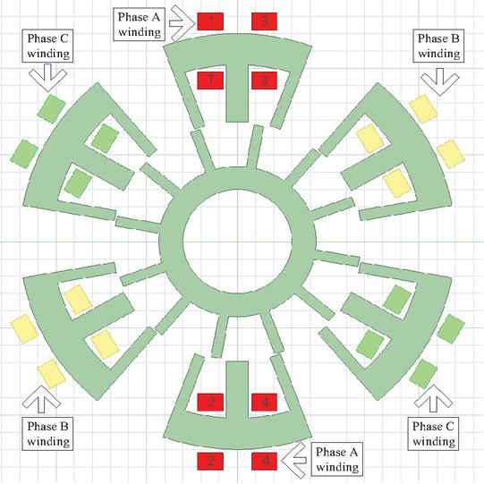
Figure 1 Stator and rotor structure of the motor.
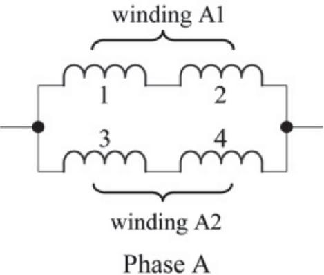
Figure 2 Diagram of phase A winding connection.
3 DESIGN OF MAIN DIMENSIONS OF E-TYPE STATOR SWITCHED RELUCTANCE MOTOR
In order to ensure that the rotor has the self-starting capability for forward and reverse rotation, when the stator and rotor teeth are completely aligned, it is necessary to ensure that there is a certain overlap between adjacent stator and rotor teeth of the same phase. Therefore, the pole arc needs to meet the relevant necessary conditions, as shown in equation (1):
| (1) |
where and represent the stator pole arc and the rotor pole arc, respectively. The slender shape of the motor is as shown in equation (2):
| (2) |
where represents the core length and represents the rotor diameter. When the value of is relatively small, the motor takes on a short and thick shape, resulting in a higher copper consumption during the manufacturing process; the motor’s rotational inertia is larger, and it is easier for heat to dissipate inside the motor. Based on the design experience of SRM, the value of generally ranges from 0.5 to 3. In this paper, the value of is set at 1.
Based on the design experience of SRM, the range of the ratio of the outer diameter of the rotor to the stator is:
| (3) |
The electromagnetic power equation of the motor is:
| (4) |
where represents the current amplitude, is the peak current coefficient, is the square wave current coefficient, represents the voltage, is the load coefficient, and is the current conduction angle during the rising phase of the winding inductance.
Ignoring the resistance of the windings on the stator, the maximum MMF can be expressed by the average MMF density of the stator poles:
| (5) |
where is the calculated length of the armature and is the average MMF density of the stator poles. Ignoring leakage flux, by combining equations (4) and (5), we can obtain:
| (6) |
The other parameters of the E-type modular stator SRM include the outer diameter of the stator (), the outer diameter of the rotor (), the yoke height between the stator and the rotor ( and ), and the length of the core (). Based on the determination of and , other parameters can be calculated. According to equation (1), the sub-pole arc is initially set at and the rotor pole arc is set at . The remaining parameters can be calculated using the following equations:
Stator pole width:
| (7) |
Rotor pole width:
| (8) |
Stator yoke height:
| (9) |
Rotor yoke height:
| (10) |
Based on the aforementioned calculation method, the initial design flowchart for the motor described in this paper is shown in Fig. 3. Using the calculated data and parameter selection criteria, the parameters for each section of the SRM were determined, as shown in Table 1.
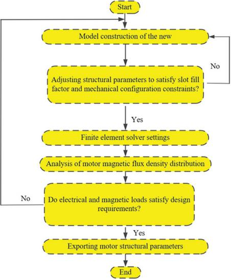
Figure 3 Motor structural design flowchart.
Table 1 Specific parameters of the designed motor
| Definition | Value |
| Number of stator poles | 18 |
| Number of rotor segments | 12 |
| Outer stator outer diameter | 120 mm |
| Inner stator outer diameter | 69 mm |
| Stator teeth slot width | 6.088 mm |
| Stator pole length | 16.5 mm |
| Stator yoke length | 9 mm |
| Rotor pole pitch coefficient | 0.5 |
| Rotor pole length | 12.3 mm |
| Air gap length | 0.5 mm |
| Winding turns per teeth | 50 |
4 FINITE ELEMENT SIMULATION CALCULATIONS AND PERFORMANCE COMPARISON
In the design of SRMs, fault tolerance is a critical characteristic. Analysis is conducted using the software Maxwell 2D. Bearing failures in SRMs can be eliminated through regular maintenance schedules, while the primary failures in these motors center on winding faults. Consequently, the impact of short-circuit or open-circuit faults in SRM windings on torque performance warrants significant attention. This paper analyzes torque data variations under missing excitation faults in windings and explores the mechanism enabling continued motor operation.
The finite element simulation adopts the commutation angle setting described in section 2. Taking phase A as an example, the current excitation is applied within the rotor mechanical angle range of to (with the non-aligned position of phase A set as the reference). The torque-rotor position curves shown in Fig. 4 (normal operation) and Fig. 5 (winding A1 failure) are obtained under this conduction scheme. For instance, when the rotor position angle is and the current is 5 A, the normal torque is (as shown in Fig. 4) and, at this time, the inductance is still in the rising zone, so the torque is positive. If the current is applied beyond (i.e., entering the inductance decline zone), a negative torque will be generated. This is avoided through the correct commutation logic. Therefore, the clear relationship between the current time (i.e., the conduction angle interval) and the rotor position is the core for generating positive torque. The results from Figs. 4–8 jointly verify that the proposed E-type stator SRM can stably output positive torque under the above commutation logic.
In the fault-tolerant research of SRM, the winding faults are mainly classified into open-circuit faults and short circuit faults. This paper focuses on open-circuit faults (i.e., the winding is disconnected from the power supply, and the excitation current is zero). The reason for choosing open-circuit faults is that this fault mode can most directly verify the magnetic circuit independence and the continued operation capability of the remaining healthy windings in the modular E-type stator SRM proposed, and it can be simulated and analyzed without additional protective hardware.
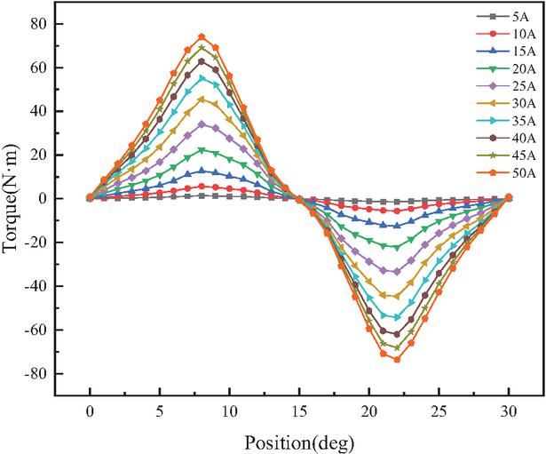
Figure 4 Normal torque characteristic curve.
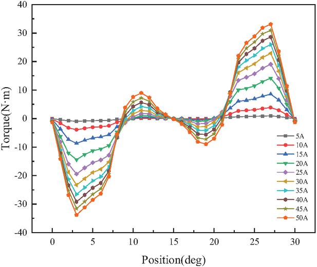
Figure 5 Torque characteristic curve when winding A1 is faulty.
During normal operation, the A1 and A2 windings are energized, generating independent and symmetrical MMF loops within the E1 and E2 modules. The two magnetic paths are not coupled in space. When the A1 winding experiences an open-circuit fault, the E1 module has no energizing current and the MMF is zero. However, the A2 winding can still normally establish the MMF, forming a complete circuit along the E2 module and the corresponding rotor section, thereby providing a continuous electromagnetic torque.
First, compare the torque data under normal operation and phase-loss fault conditions. From the data in Figs. 4 and 5, it can be seen that in the case of fault in winding A1, the torque values are generally lower than the normal situation. For example, at the rotor position angle of 0 degrees and current of 5 A, the normal torque is 0.01676 Nm, while the phase-loss torque is 0.03647 Nm, indicating that the phase-loss not only reduces the torque output but also introduces a negative torque region. Similarly, at different currents and positions, the amplitude of the phase-loss torque decreases and the fluctuations increase. This is mainly because the torque of the SRM is generated by multiple phase windings together. When winding A1 is faulty, the total torque synthesis decreases, and the torque pulsation increases, resulting in a decrease in the average torque and unstable operation.
The reason for the torque difference under the phase loss fault lies in the working principle of the SRM. During normal operation, each phase winding is excited in sequence, and the magnetic resistance change caused by the rotor position variation is utilized to generate continuous torque. When phase A1 is missing, it does not contribute to the torque, so the torque output depends on the remaining phases. However, the excitation of the remaining phases may not fully cover all rotor positions, resulting in low torque or negative torque at certain positions. Moreover, due to magnetic circuit coupling, the phase loss may change the flux distribution, further affecting the torque characteristics.
Despite the torque performance degradation caused by phase loss, the motor can continue to operate. This is because the designed SRM structure possesses inherent fault tolerance. Each phase winding is relatively independent in both electrical and magnetic circuits, so a fault in winding A1 does not directly affect the operation of other phases. The remaining phase windings can continue to generate torque, driving the rotor rotation. Although output torque decreases and pulsation increases, the motor can maintain operation in many applications, especially if the load demands are not high or the control system can adjust the current to compensate for the torque loss. Furthermore, the designed SRM features a simple structure and robustness that ensures reliability under fault conditions.
To validate the magnetic circuit and operating principle of the modular E-shaped core stator in the novel switch reluctance motor, a finite element analysis model was constructed based on the motor structural parameters provided in Table 1. This model was used to evaluate the electromagnetic performance of the new SRM. Figure 6 illustrates the finite element model structure of the modular novel motor and its magnetic field distribution characteristics under excitation conditions.
Analysis of the MMF density distribution reveals that the magnetic field distribution in the tooth regions and winding areas of both the stator and rotor cores is relatively uniform, with no significant localized saturation observed. It should be noted that peak MMF density is primarily concentrated near the pole tips adjacent to the air gap, a distribution characteristic consistent with the physical principles governing magnetic field control. Simulation results indicate that, throughout the entire operating cycle, the maximum MMF density in the core material consistently remains below 1.01 T. This data not only demonstrates the efficient utilization of magnetic materials but also validates the rationality and reliability of the proposed motor structure from an electromagnetic design perspective.
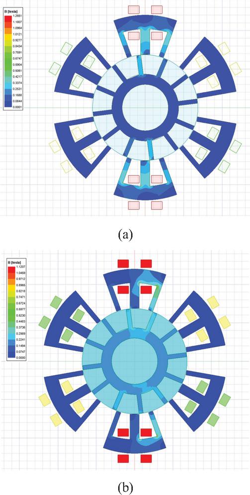
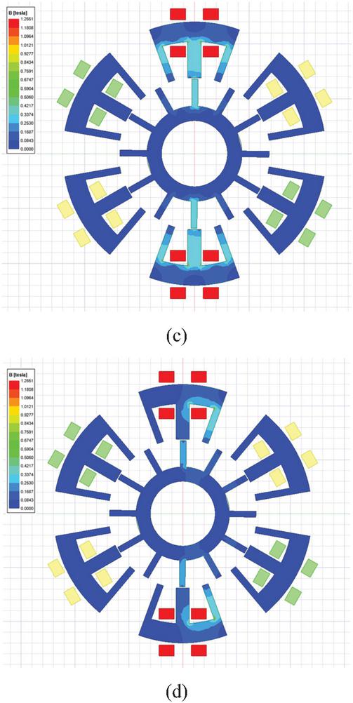
Figure 6 Finite element model and magnetic field distribution: (a) normal magnetic flux density map misaligned position, (b) magnetic flux density cloud map during A1 winding fault – misaligned position, (c) normal magnetic flux density map – alignment position, and (d) magnetic flux density cloud map during A1 winding fault – alignment position.
From the MMF density distribution in Fig. 6, it can be seen that the maximum MMF density of the iron core of the motor in this study is 1.01–1.27 T, which is significantly lower than the 1.5–1.7 T commonly used in conventional motor designs. This choice was not accidental but was based on the following considerations: (a) to reserve magnetic circuit saturation margin for the current increase of the remaining healthy windings in case of open-circuit faults; (b) to reduce core loss and improve efficiency; (c) to reduce radial magnetic suction pulsation and suppress noise and vibration; (d) to maintain the linearity of the magnetic circuit near the normal operating point for easier control.
If higher requirements are imposed on volume and weight, the iron core size can be reduced by increasing the MMF density. For example, if the maximum MMF density is raised to 1.5 T, the stator tooth width and yoke height can be reduced accordingly, and the core volume is expected to shrink by approximately 35%. However, the cost is a significant increase in iron loss (about 2.5 times), and the torque pulsation and noise levels also increase. Therefore, the conservative MMF density design adopted in this study is more suitable for high-reliability and low-noise applications; for applications that require high power density, the motor can be optimized for high MMF density in subsequent work.
The core electromagnetic characteristics of SRMs are embodied in key parameters such as MMF linkage, inductance, and output torque. Figures 7 and 8 illustrate the variation patterns of MMF linkage and inductance across a single stator pole with current changes under normal operating conditions and single-winding fault conditions.
Figure 7 shows the flux-current curves for a single stator pole at both aligned and non-aligned positions during a winding A1 fault. As illustrated, at low currents, the flux at both positions increases approximately linearly with current. As current continues to rise, the flux growth at the aligned position slows significantly, exhibiting a saturation trend, indicating that the pole tip region enters a state of local magnetic saturation. In contrast, the MMF at the non-aligned position maintains a consistent linear relationship throughout the entire current range. This comparison demonstrates that, under winding fault conditions, the spatial distribution characteristics of the motor’s MMF remain consistent with normal operating conditions. The peak MMF density remains concentrated near the air gap at the aligned position, adhering to the fundamental physical principles of magnetic field distribution. This also indirectly reflects that the motor structure retains a certain degree of electromagnetic stability even under localized faults.
Figure 7 shows the pattern of the MMF as it varies with the current. In the normal operating condition (Fig. 7 (a)), the MMF at the aligned position (red line) linearly increases in the low current region. When the current exceeds 2 A, it enters the saturation region, and the slope of the curve gradually decreases. The MMF at the non-aligned position (black line) remains linear throughout the current range and is much lower than that at the aligned position (for example, at 2 A, the MMF at the non-aligned position is only 25% of that at the aligned position). This is in line with the basic characteristics of the SRM. When an A1 winding open-circuit fault occurs (Fig. 7 (b)), due to the absence of A1 winding excitation, the total phase MMF is halved, resulting in a decrease of approximately 20.7% in the MMF at the aligned position compared to the normal operating state (at 5 A current, it drops from 0.0605 Wb to 0.0480 Wb); while the MMF at the non-aligned position is almost unaffected (because the magnetic path at this position is mainly composed of air gaps, with a large magnetic resistance, and the effect of halving the number of windings can be ignored).
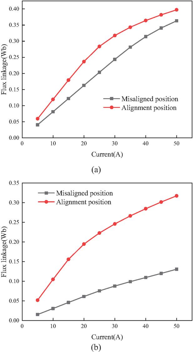
Figure 7 Magnetic linkage curve diagram: (a) normal operation (both A1 and A2 are in normal excitation state) and (b) open-circuit fault in the A1 winding (A2 is operating normally; the current in A1 is zero).
Figure 8 further compares the inductance-current curves during normal operation and when winding A1 is faulty. During normal operation, the inductance at the aligned position remains stable at low currents but decreases significantly upon entering the saturation region. The inductance at the non-aligned position exhibits smooth variation across the entire current range. After the A1 winding failure, the overall trend of the inductance curve remains unchanged. However, the inductance value at the aligned position in the saturation region slightly decreases, while the inductance characteristics at the non-aligned position remain virtually unaffected. These results indicate that the winding fault did not alter the inherent saturation characteristics of the motor’s magnetic circuit. The distinct response differences between the aligned and non-aligned positions remain clearly discernible. This further confirms that the designed motor exhibits a certain degree of robustness against localized faults at the electromagnetic parameter level, providing a basis for analyzing the motor’s fault-tolerant operation.
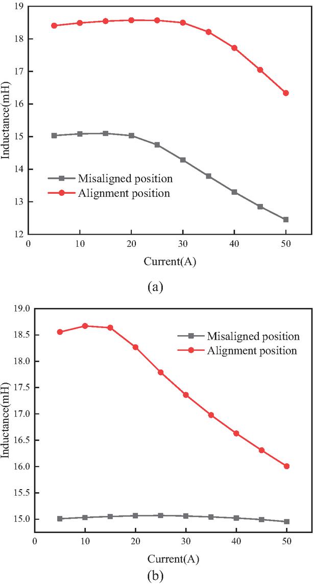
Figure 8 Inductance curve graph: (a) normal operation (both A1 and A2 are in normal excitation state) and (b) open-circuit fault in the A1 winding (A2 is operating normally; the current in A1 is zero).
As can be seen from Table 2, the analytical values are in good agreement with the finite element values, and all relative errors are within 3%. The errors mainly result from the fact that the analytical model did not take into account the non-linear saturation of the core material and the edge effect of the tooth tips. This verification result indicates that although the analytical model contains certain approximations, its design accuracy is sufficient to meet the requirements of the initial engineering design, and it also provides a reliable initial size for the subsequent finite element optimization.
Table 2 Comparison of analytical calculation results with finite element simulation results (5 A)
| Performance | Analysis | Finite | Relative |
| Indicators | Calculation | Element | Error |
| Value | Simulation | ||
| Values | |||
| Aligned position magnetic link | 0.0595 Wb | 0.0580 Wb | 2.5% |
| Its position inductance | 12.4 mH | 11.8 mH | 2.5% |
| Non-aligned position inductor | 2.78 mH | 2.82 mH | 1.4% |
During the initial stage of excitation with lower currents, the MMF at both positions increases approximately linearly with the excitation current, while the corresponding inductance values remain largely constant. This indicates that the motor’s magnetic circuit is operating within the linear region of the core material’s magnetization curve. However, once the current exceeds a specific saturation threshold, the MMF growth at the aligned position slows significantly, exhibiting nonlinear saturation characteristics, and its inductance value decreases markedly. In contrast, the MMF and inductance at the misaligned position exhibit smooth variations across the entire current range, maintaining a consistently good linear relationship throughout.
5 CONCLUSION
The E-type stator modular structure of the SRM is relatively simple in terms of manufacturing and maintenance. The simulation results have proved the fault-tolerant capability and reliability of the proposed SRM. Even in the case of severe open-circuit faults in the windings, it can still perform the task well. Of course, in this situation, the torque pulsation of the SRM will become larger, the speed will decrease, and the period of low torque will be prolonged due to the increase in the number of current pulses missing. In the future, studies will be conducted to reduce the torque pulsation through an appropriate current control system, increase the current in the remaining healthy windings of the stator, and further improve the reliability of the SRM.
ACKNOWLEDGMENT
This work was supported in part by the National Natural Science Foundation of China International (regional) cooperation and exchange projects NSFC-RSF under Grant W2412064.
REFERENCES
[1] W. Yan, W. Wang, H. Li, H. Chen, F. Yu, D. Zhang, H. Yang, and Q. Wang, “Investigation on different stator structures of the axial-radial flux switched reluctance motors,” IEEE Transactions on Industrial Electronics, vol. 71, no. 6, pp. 5474–5484, June 2024.
[2] G. Wang, H. Chen, F. Yu, W. Yan, X. Wang, M. Benbouzid, A. Bresolin, M. P. Aguirre, H. Torkaman, M. Shamiev, Y. Tairov, M. Orabi, and M. A. Gaafar, “Design, analysis, and comparison of a novel axial flux modular-double-stator hybrid excitation SRM,” IEEE Transactions on Transportation Electrification, vol. 10, no. 3, pp. 6100–6114, Sep. 2024.
[3] H. Chen, C. Fang, G. Guan, and N. Parspour, “Fault diagnosis for power converter in SRM drives based on current prediction,” IEEE Transactions on Industrial Electronics, vol. 69, no. 12, pp. 13576–13585, Dec. 2022.
[4] F. Yu, H. Chen, W. Yan, and X. Wang, “Three-switch reconfigurable winding power converter and online mode-changeover methods for SRM speed range extension,” IEEE Transactions on Transportation Electrification, vol. 11, no. 1, pp. 2061–2075, Feb. 2025.
[5] X. Ojeda, X. Mininger, H. B. Ahmed, M. Gabsi, and M. Lecrivain, “Piezoelectric actuator design and placement for switched reluctance motors active damping,” IEEE Trans. Energy Convers., vol. 24, no. 2, pp. 305–313, 2009.
[6] B. C. Mecrow, E. A. El-Kharashi, J. W. Finch, and A. G. Jack, “Segmental rotor switched reluctance motors with single-tooth windings,” IEE Proc. Electr. Power Appl., vol. 150, no. 5, pp. 591–599, 2003.
[7] R. Madhavan and B. G. Fernandes, “Axial flux segmented SRM with a higher number of rotor segments for electric vehicles,” IEEE Trans. Energy Convers., vol. 28, no. 1, pp. 203–213, 2013.
[8] A. Labak and N. C. Kar, “Designing and prototyping a novel five-phase pancake-shaped axial-flux SRM for electric vehicle application through dynamic FEA incorporating flux-tube modeling,” IEEE Transactions on Industry Applications, vol. 49, no. 3, pp. 1276–1288, May–June 2013.
[9] C. Lee and R. Krishnan, “New designs of a two-phase E-core switched reluctance machine by optimizing the magnetic structure for a specific application: Concept, design, and analysis,” IEEE Trans. Ind. Appl., vol. 45, no. 5, pp. 1804–1814, 2009.
[10] C. Lee, R. Krishnan, and N. S. Lobo, “Novel two-phase switched reluctance machine using common-pole E-core structure: Concept, analysis, and experimental verification,” IEEE Trans. Ind. Appl., vol. 45, no. 2, pp. 703–711, 2009.
[11] F. Yu, H. Chen, W. Yan, V. F. Pires, J. F. A. Martins, P. Rafajdus, A. Musolino, L. Sani, M. P. Aguirre, M. A. Sagib, M. Orabi, and X. Li, “Design and multiobjective optimization of a double-stator axial flux SRM with full-pitch winding configuration,” IEEE Transactions on Transportation Electrification, vol. 8, no. 4, pp. 4348–4364, Dec. 2022.
[12] S. Cai, Y. Wang, H. Chen, X. Yuan, L. Yu, Z. Zhang, C. H. T. Lee, “Design and analysis of a doubly salient wound field starter generator for cost-effective automobile application,” IEEE Transactions on Vehicular Technology, vol. 71, no. 7, pp. 6900–6911, July 2022.
[13] K. Nakamura, T. Ono, H. Goto, T. Watanabe, and O. Ichinokura, “A novel switched reluctance motor with wound-cores put on stator and rotor poles,” IEEE Trans. Magn., vol. 41, no. 10, pp. 3919–3921, 2005.
[14] S. H. Mao and M. C. Tsai, “A novel switched reluctance motor with C-core stators,” IEEE Trans. Magn., vol. 41, no. 12, pp. 4413–4420, 2005.
[15] Y. K. Choi, H. S. Yoon, and C. S. Koh, “Pole-shape optimization of a switched reluctance motor for torque ripple reduction,” IEEE Trans. Magn., vol. 43, no. 4, pp. 1797–1800, 2007.
[16] H. Torkaman, E. Afjei, and M. S. Toulabi, “New double-layer-per-phase isolated switched reluctance motor: Concept, numerical analysis, and experimental confirmation,” IEEE Trans. Ind. Electron., vol. 59, no. 2, pp. 830–838, 2012.
[17] C. S. Kim, G. Lee, K. Lee, J. Lee, and Y. Cho, “Design of core and core PM-aided switched reluctance motors,” in Proc. IEEE Int. Conf. Electric Vehicle, Kuching, Malaysia, pp. 1–6, 2012.
BIOGRAPHIES

Hao Chen (SM’08) received the B.S. and Ph.D. degrees from the Department of Automatic Control, Nanjing University of Aeronautics and Astronautics, Nanjing, China, in 1991 and 1996, respectively. In 1998, he became an Associate Professor with the School of Information and Electrical Engineering, China University of Mining and Technology, Xuzhou, where he has been a Professor since 2001. From 2002 to 2003, he was a Visiting Professor at Kyungsung University, Busan, Korea. Since 2008, he has also been an Adjunct Professor at the University of Western Australia, Perth, Australia. He is the author of one book and has also authored more than 190 papers. He is the holder of 15 US Patents, 23 Australian Patents, one Danish Patent, seven Canadian Patents, three South African Patents, 10 Russian Patents, 86 Chinese Invention Patents, and six Chinese Utility Model Patents. His current research interests include motor control, linear launcher, electric vehicles, electric traction, servo drives, and wind power generator control.
Chen was the recipient of both the Prize of Science and Technology of Chinese Youth and the Prize of the Fok Ying Tong Education Foundation for Youth Teachers in 2004. He was awarded first prize in the Science and Technology advanced of Province and Ministry once, second prize in the Science and Technology advanced of Province and Ministry seven times, and third prize in the Science and Technology advanced of Province and Ministry 14 times. He became the Chinese New Century Hundred-Thousand Ten-Thousand Talents Engineering National Talent in 2007, and won the Government Especial Allowance of People’s Republic of China State Department in 2006.

Xin Liu obtained a master’s degree in electrical engineering. Since 2024, he has been studying for a doctoral degree in electrical engineering at China University of Mining and Technology in Xuzhou, China. His research interests include switched reluctance drive, special motor design, power converters, and motor control.

Sergei Brovanov received the engineer degree from the Industrial Electronics Department, Novosibirsk Electrotechnical Institute, Russia, in 1987. In 1999, he became an Associate Professor in the Industrial Electronics Department, Novosibirsk State Technical University, where he has been a Professor since 2013. In 2004, he was a Visiting Professor at Ulsan University, South Korea. He is the author of one book and has also authored more than 150 papers. He has obtained 17 Russian patents. His current research interests include semiconductor converters, vector PWM of multilevel NPC converters, and semiconductor converters for electrical energy storage systems. In 1996–1997, he was awarded a scholarship from the Swiss Academy of Engineering Sciences. In 2023, he was awarded the State Prize of the Novosibirsk Region for the development of intelligent power electronic systems and devices. Brovanov currently is a professor in the electronics and electrical engineering department at Novosibirsk State Technical University.

Jason Gu (Senior Member, IEEE) received the B.Eng. degree in electrical engineering and information science from the University of Science and Technology of China, Hefei, China, in 1992, the M.A.Sc. degree in biomedical engineering from Shanghai Jiaotong University, Shanghai, in 1995, and the Ph.D. degree in electrical and computer engineering from the University of Alberta, Edmonton, AB, Canada, in 2001. He is currently a Professor of electrical and computer engineering with Dalhousie University, Halifax, NS. He is also a Cross-Appointed Professor with the School of Biomedical Engineering for his multidisciplinary research work. He is a Guest Professor with Shandong University, Jinan. His current research interests include robotics and teleoperation, biomedical engineering, rehabilitation engineering, neural networks, and control.

Sherif Moussa is the Dean of the School of Engineering, Applied Science, and Technology at the Canadian University Dubai (CUD), UAE. He earned his Ph.D. in Electrical and Computer Engineering from the University of Québec at Trois-Rivières, Canada, and his M.Sc. in Electrical and Computer Engineering from the University of Waterloo, Canada. Since joining CUD in 2007, Moussa has led the School’s remarkable growth, overseeing the launch and accreditation of several engineering and computing programs, including mechatronics engineering, computer science, cybersecurity, software design, power and renewable energy engineering, and the M.Sc. in Artificial Intelligence. His leadership has also advanced international collaborations, notably with Queen’s University and the University of Ottawa, and strengthened CUD’s engagement with industry partners in emerging technologies. Moussa’s research interests span wireless communication, computer networks, machine learning, and digital systems design. He has published widely in international journals and conferences, serves on technical committees, and was the recipient of the 2015 CUD Research Excellence Award. He is also the founder of CUD’s Robotics Club and a strong advocate for innovation and experiential learning in engineering education.

Marcin Wardach was born in Poland in 1980. He graduated and received the Ph.D. degree from the Electrical Department, Szczecin University of Technology, Szczecin, Poland, in 2004 and 2009, respectively. From 2020 until now, he has been an Associate Professor with the Faculty of Electrical Engineering, West Pomeranian University of Technology in Szczecin. Since 2024, he has served as Vice-Dean for Organization and Development and Head of the Department of Electrical Machines and Drives at the Faculty of Electrical Engineering, West Pomeranian University of Technology in Szczecin. From 2019 to 2025, he worked as an electrical machine designer at Mpower Sp. z o.o. company. His research interests include the design of electrical machines and drives, especially unconventional and hybrid excited. He is the author of over 100 scientific papers and post-conference publications. Since 2022, he has been the President of the Szczecin Branch of the Association of Polish Electrical Engineers (SEP). He is also a member of the Polish Society of Theoretical and Applied Electrical Engineering.

Javokhir Toshov received the B.S. degree from Navoi State Mining Institute, Navoi, Uzbekistan, in 1999, and M.S. degree from Tashkent State Technical University, Tashkent, in 2002. Dr.Sci. in 2017, Professor of the Tashkent State Technical University since 2020. He has about 250 published and reviewed works. His current research interests include drilling control for drilling operations, as well as electrical installations and motors for mining equipment. For many years he worked as the dean of the energy faculty, and today he works as the head of the department at Tashkent State Technical University.

Ali Asghar Memon is professor in Electrical Engineering at Mehran University of Engineering and Technology Jamshoro, Pakistan. He holds B.E. and M.E. both in Electrical Engineering from Mehran University and Ph.D. from University of Leeds, UK. Memon is head of Electrical Machine and Drives group at Mehran University. He has been member of National Curriculum Review Committee in Pakistan. Memon has been serving as an expert evaluator for National Research Project for Universities (NRPU), Post doc fellowship and project(s) under Technology Development Fund (TDF), under Higher Education Commission (HEC), Government of Pakistan. Memon is keynote speaker and reviewer of prestige international research journals. Memons interests include modeling and simulation of switched reluctance machines and inverters.

Xing Wang received the B.S. degree from China University of Mining and Technology, Xuzhou Jiangsu, China, in 1996, and M.S. degree from China University of Mining and Technology, Xuzhou Jiangsu, in 1999. In 2007, she became an Associate Professor with China University of Mining and Technology, Xuzhou. She is a holder of four US Patents, nine Australian Patents, two Canadian Patents, four Russian Patents, 12 Chinese Invention Patents, three Chinese Utility Model Patents, and has authored 15 papers.
ACES JOURNAL, Vol. 41, No. 6, 566–576
DOI.org/10.13052/2026.ACES.J.410607
© 2026 River Publishers