Electromagnetic Analysis of a 12-Pole Single-Phase Switched Reluctance Linear Motor
Hao Chen1, 2, 3, Denis Kotin4, Aris Dimeas5, Emmanuel Karapidakis6, Olimjon Toirov7, Liu Jingfu2, Zhao Wenmin2, Xing Wang1, 3*, and Sherif Moussa8
1International Cooperation Joint Laboratory of New Energy Power Generation and Electric Vehicles of Jiangsu Province Colleges and Universities, Xuzhou 221008, China
hchen@cumt.edu.cn, 3512@cumt.edu.cn
2School of Electrical Engineering China University of Mining and Technology, Xuzhou 221116, China
hchen@cumt.edu.cn, liujinfu99@cumt.edu.cn
3Shenzhen Research Institute China University of Mining and Technology, Shenzhen 515100, China
4Department of Electric Drive and Industry Automation Novosibirsk State Technical University, 630073, 20 Prospekt K. Marksa, Novosibirsk, Russia
d.kotin@corp.nstu.ru
5Athens National University of Technology Greece
karapidakis@hmu.gr
6School of Engineering, Hellenic Mediterranean University Estavromenos Campus, 71004 Heraklio, Crete, Greece
karapidakis@hmu.gr
7Tashkent State Technical University University Street No. 2, 100095 Tashkent, Uzbekistan
olimjon.t@mail.ru
8School of Engineering, Canadian University Dubai 117781, Sheikh Zayed Road, Dubai, United Arab Emirates
smoussa@cud.ac.ae
Submitted On: March 23, 2026
Accepted On: May 27, 2026
ABSTRACT
A novel modular 12-pole transverse-flux tubular switched reluctance linear machine (TSRLM) is proposed in this paper. The machine adopts a U-shaped modular-stator structure with windings arranged on the stator yoke, which shortens magnetic flux paths, reduces magnetic reluctance, and improves iron core utilization. A three-dimensional finite-element model is established to analyze the electromagnetic characteristics of the proposed TSRLM, including flux linkage, static electromagnetic force, and magnetic field distribution. On this basis, a sensitivity-based single-objective optimization is conducted to determine the structural parameters of the motor. Then, a 12-pole TSRLM prototype is fabricated, and dynamic motoring experiments are carried out under different current chopping limits. Experimental results agree well with simulation results, validating the accuracy of the finite-element model and the feasibility of the proposed design.
Keywords: Finite-element analysis, modular-stator, transverse-flux, tubular switched reluctance linear machine..
1 INTRODUCTION
Switched reluctance motors (SRMs) are special electric machines with high robustness, simple manufacturing processes, low cost, simple construction, strong fault tolerance, wide speed regulation range, and good adaptability to harsh operating environments [1, 2, 3]. Owing to these merits, SRMs have attracted increasing attention from researchers worldwide in recent years [4, 5, 6, 7]. Flat-type linear machines are affected by both lateral end effects and longitudinal end effects [8]. The lateral end effect arises from the unequal lengths of the primary and secondary parts, while the longitudinal end effect is caused by the finite machine length resulting from the interruption of the magnetic circuit at the longitudinal ends. The longitudinal end effect leads to differences between the magnetic circuits of the end phases and the middle phases, resulting in inductance imbalance among phases. Consequently, phase currents and output forces become unbalanced, which aggravates electromagnetic force ripple and reduces the service life of the machine.
By rotating a flat-type SRLM through one full revolution along a circular path perpendicular to the direction of motion, a tubular switched reluctance linear motor (TSRLM) can be obtained [9, 10]. The cross-sectional structure of the TSRLM is highly similar to that of a rotary switched reluctance motor (RSRM). By combining the advantages of tubular machines and SRLMs, the TSRLM inherently eliminates lateral end effects, thereby reducing analytical complexity. Moreover, the tubular structure eliminates the normal electromagnetic force between the stator and the mover, effectively addressing the eccentricity problem inherent in flat-type linear machines. As a result, a smaller air gap can be adopted, leading to a significant improvement in electromagnetic force density.
Over the more than four decades of development of SRMs, their performance has gradually become sufficient to meet practical application requirements. However, conventional SRMs have long faced difficulties in large-scale manufacturing, resulting in low production efficiency and increased manufacturing costs. To address this issue, the concept of modular machine design has been proposed. Compared with traditional SRMs, modular SRMs exhibit advantages such as lower cost, higher torque capability, strong fault tolerance, and reduced losses. Modularization is conducive to expanding production scale, improving manufacturing efficiency, shortening production cycles, and further promoting the development of SRMs, thereby significantly enhancing their industrial competitiveness. Wang et al. [11] proposed a novel modular secondary-side SRLM with annular windings. The stator is composed of multiple mutually independent ferromagnetic modules, and the stator yoke is eliminated to effectively isolate adjacent magnetic blocks. Only one phase armature winding is placed in each stator slot, and no inter-phase insulation is required, which reduces manufacturing cost and significantly improves iron core utilization. As a result, the overall performance of the machine is effectively enhanced. In [1]], two segmented E-shaped rotors with different structures are comprehensively analyzed. Ding et al. [13] proposed a modular-rotor SRM with an E-shaped stator configuration. The stator is composed of six mutually independent E-shaped stator modules, with the windings arranged on the stator yokes. The rotor is divided into three segments corresponding to the stator poles, and the three segmented rotors are mounted on a common shaft without any angular displacement. Ruba et al. [14] proposed a modular-stator SRM with high fault tolerance and conducted a dynamic simulation study. The machine is a four-phase SRM, with two stator modules per phase. The winding of each stator module is wound around the corresponding stator yoke, and the two winding modules of each phase are positioned at diametrically opposite locations along the circumference. Adjacent stator modules are separated by non-magnetic spacers.
In summary, although tubular switched reluctance linear machines and modular SRM topologies have been extensively investigated, most existing studies focus either on modular concepts in rotary SRMs or on conventional tubular linear structures, while the combination of modular-stator topology and transverse-flux tubular SRLMs remains insufficiently explored. Moreover, issues related to electromagnetic characteristics, magnetic field distribution, and experimental validation of such modular tubular structures are still not fully addressed. Motivated by these considerations, this paper proposes a novel 12-pole modular TSRLM with U-shaped stator topology. The structural configuration and operating principle of the proposed machine are introduced in detail. A three-dimensional finite-element model is established to analyze its electromagnetic characteristics, including flux linkage, static electromagnetic force, and magnetic field distribution. Furthermore, a prototype is fabricated and experimentally tested to validate the proposed design and the accuracy of the modeling approach. The results demonstrate the feasibility and effectiveness of the proposed modular TSRLM structure.
2 STRUCTURE AND PRINCIPLE OF MS-6P-TSRLG
2.1 Basic structure of MS-6P-TSRLG
The modular TSRLM proposed in this paper inherits the typical characteristics of SRLMs, and its overall shape and structure are highly similar to those of a conventional RSRM, especially in terms of the cross-sectional configuration. Owing to the very low magnetic permeability of air, both the stator and mover cores are fabricated by stacking silicon steel laminations. The structure of the 12-pole TSRLM is illustrated in Fig. 1. Figure 1 (a) shows the cross-sectional view of the 12-pole TSRLM and the corresponding magnetic flux paths. The stator consists of six U-shaped modular-stator units, and adjacent stator modules are separated by stator spacers made of non-magnetic material, which effectively suppresses magnetic leakage between modules. The windings are wound around the stator yokes of the U-shaped modules and connected in an NSNSNSNSNSNS sequence using conductors with a diameter of 1.5 mm. The entire machine includes five stator ferromagnetic rings, which are mechanically connected by fastening bolts passing through the stator spacing rings.
The mover structure is shown in Fig. 1 (b). Each mover ferromagnetic ring contains six gear-shaped salient poles. These poles are inserted into the openings of the modular-stator cores, such that each mover pole and each U-shaped stator module together form a closed stator slot structure. This configuration is conducive to establishing an effective magnetic circuit and helps to enhance the thrust density of the machine. The mover assembly consists of five ferromagnetic rings uniformly mounted on the shaft with specified spacing. The ferromagnetic materials used for both the stator and the mover are 50DW470 silicon steel laminations. The shaft material is the same as the non-magnetic material used between adjacent stator modules. Similarly, non-magnetic materials are inserted between adjacent stator ferromagnetic rings and between adjacent mover ferromagnetic rings to prevent the formation of axial magnetic flux.
The proposed 12-pole TSRLM is a transverse-flux machine, in which the plane of the magnetic circuit is perpendicular to the direction of motion. Once axial magnetic flux is generated, mutual coupling may occur between adjacent ferromagnetic rings, leading to severe distortion of axial flux lines and degradation of machine performance. To avoid this phenomenon, non-magnetic materials are employed to separate the stator ferromagnetic rings.
The structure of the 12-pole TSRLM in this paper is illustrated in Fig. 1. When the windings are energized, closed magnetic flux paths are established through the ferromagnetic materials and air gaps. The magnetic flux paths mainly consist of two loops. One loop passes through the stator yoke of the U-shaped module, the stator pole of the U-shaped module, and the air gap between the stator pole and the mover pole. The other loop passes through the stator yoke of the U-shaped module, the stator pole of the U-shaped module, and the air gap between the stator pole and the mover yoke. These closed magnetic circuits are formed within each U-shaped stator pole, which effectively shortens the magnetic path, reduces magnetic reluctance, and significantly improves the overall performance of the machine.
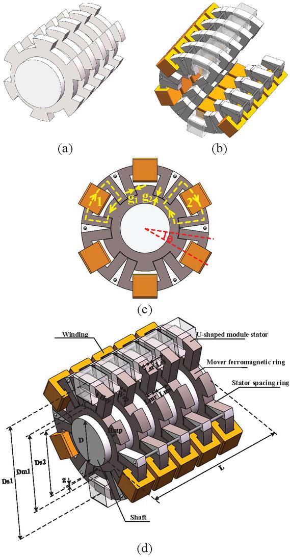
Figure 1 Structure of the 12-pole TSRLM: (a) segmented mover, (b) segmented stator, (c) stator cross-section, and (d) overall structure.
In conventional machines, the windings are typically placed on the stator poles, and the number of turns that can be accommodated is constrained by two factors: the available stator slot space in the cross-sectional direction and the axial spacing between two adjacent stator ferromagnetic rings. In such configurations, two winding modules are usually arranged in each stator slot, and the allowable number of turns is determined by the smaller of the two available spaces, namely the stator slot area and the axial spacing between the ferromagnetic rings.
In contrast, in the 12-pole TSRLM proposed in this paper, the windings are wound around the stator yoke. As a result, only one winding module is placed in each stator slot in a given stator cross-section. This configuration eliminates the limitation imposed by the stator slot space in the cross-sectional direction, and the winding accommodation is determined solely by the axial spacing between adjacent stator rings. This winding arrangement significantly reduces manufacturing complexity, facilitates an increase in the number of winding turns, and consequently enhances the overall performance of the machine.
2.2 Principle of the 12-pole TSRLM
The TSRLM is a reluctance-based machine and differs fundamentally from conventional electrical machines. As the mover travels, the magnetic reluctance of the TSRLM varies continuously, causing the magnetic field energy to change with the mover position. During operation, the TSRLM follows the principle of minimum reluctance, that is, the magnetic flux always tends to close along the path with the minimum magnetic reluctance. Owing to this operating mechanism, its structure and working principle are markedly different from those of conventional machines. Figure 2 illustrates the structural principle of the 12-pole TSRLM. The operating process can be described as follows.
When switches S1 and S2 are turned on, the DC power supply U energizes the windings. The radial electromagnetic force generated by the distorted magnetic field tends to drive the mover toward the position where the central axis of the mover pole aligns with that of the stator pole, namely the aligned position. When the mover reaches this aligned position, the magnetic reluctance and leakage flux are minimized, and the corresponding flux linkage, electromagnetic force, and inductance reach their maximum values within one mover period. As the mover continues to move and deviates from the aligned position, the magnetic reluctance and leakage flux increase, while the flux linkage, electromagnetic force, and inductance decrease accordingly. Excitation of the stator windings always produces a radial electromagnetic force that tends to align the central axes of the stator and mover poles, thereby driving the mover back toward the aligned position.
The direction of the excitation current in the windings does not affect the direction of motion of the machine, which allows the use of a relatively simple power converter topology. When switches S1 and S2 are turned off, the winding current flows through the freewheeling diodes VD1 and VD2, and the remaining electrical energy is fed back to the power supply U. This energy recovery process is beneficial for improving the overall efficiency of the system.
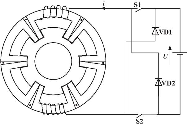
Figure 2 Structural schematic diagram of the 12-pole TSRLM.
3 ELECTROMAGNETIC ANALYSIS OF THE 12-POLE TSRLM
3.1 Electromagnetic characteristic curves of the 12-pole TSRLM
The finite-element model established in this paper is shown in Fig. 3. Among them, the ferromagnetic materials for both the stator and rotor parts are all 50DW470.
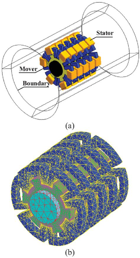
Figure 3 Finite-element model of the 12-pole TSRLM: (a) model and its boundaries and (b) model after meshing.
For the 12-pole TSRLM investigated in this paper, one mover period is 10 mm, and the mover stroke ranges from 5 mm to 5 mm. Following conventional design practice, the position at which the central axis of the stator pole is perfectly aligned with that of the mover pole is defined as the 0 mm position, i.e., the aligned position. Taking the 0 mm position as the reference, the mover travels 5 mm in the negative direction to the 5 mm position and 5 mm in the positive direction to the 5 mm position. At both the 5 mm and 5 mm positions, the stator and mover poles are completely misaligned, corresponding to the unaligned positions.
The settings of the TSRLM finite-element model are modified by assigning the excitation current in the range of 0–15 A with a step size of 1 A, and restricting the mover position to the range of 5 mm to 0 mm with a step size of 0.5 mm. As the mover position varies, the finite-element model is remeshed, and the flux linkage and magnetic co-energy are calculated for different current levels at each mover position. By repeating this procedure sequentially, accurate finite-element results are obtained. Figure 3 shows the three-dimensional surfaces of the flux linkage and magnetic co-energy as functions of mover position and excitation current, obtained from the finite-element analysis.
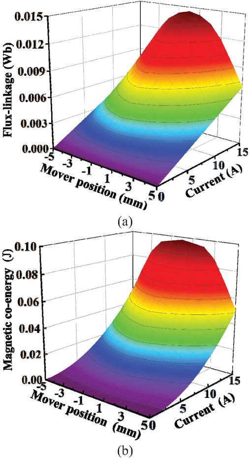
Figure 4 Three-dimensional curves of flux linkage and magnetic energy of the 12-pole TSRLM varying with current and mover position: (a) calculation results of flux-linkage and (b) calculation results of magnetic co-energy.
According to Fig. 4 (a), at a given mover position, the flux linkage increases overall with increasing current and, near the aligned position, the magnetic circuit exhibits a clear tendency toward saturation as the current rises. For a given current level, when the mover travels from the unaligned position at 5 mm to the aligned position at 0 mm, the flux linkage increases and reaches its maximum at the 0 mm position. During transition from the unaligned position to the aligned position, the magnetic circuit gradually approaches saturation, and the flux linkage exhibits pronounced nonlinear characteristics. The variation trend of flux linkage when the mover moves from the 5 mm position toward 0 mm is completely symmetric to that observed when the mover moves from 5 mm toward 0 mm. Moreover, for different current levels, the flux linkage exhibits the same variation trend with respect to the mover position.
As shown in Fig. 4 (b), the variation trends of the magnetic co-energy with respect to mover position and current are consistent with those shown in Fig. 3 (a); therefore, they are not repeated here.
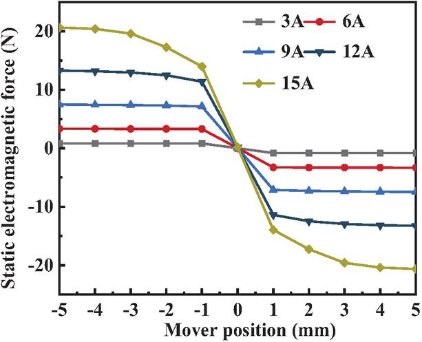
Figure 5 Static electromagnetic force curves under different mover positions and currents.
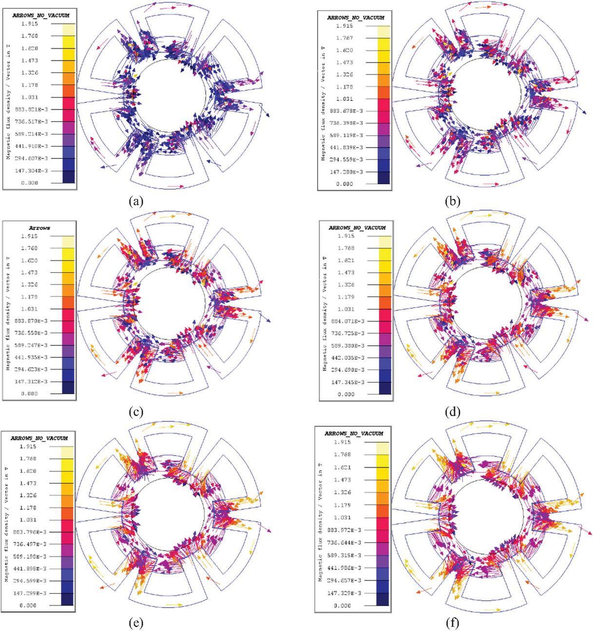
Figure 6 Flux paths of the 12-pole TSRLM in different mover positions: (a) 5 mm, (b) 4 mm, (c) 3 mm, (d) 2 mm, (e) 1 mm, and (f) 0 mm.
Figure 5 shows the static electromagnetic force curves within one mover period under different mover positions and excitation current levels. Five static electromagnetic force curves corresponding to excitation currents of 3 A, 6 A, 9 A, 12 A, and 15 A are presented. As can be observed from Fig. 5, for a given current level, when the mover travels from the 5 mm position toward the 0 mm position, the magnitude of the static electromagnetic force gradually decreases. When the mover reaches the 0 mm position, where the magnetic reluctance is minimized, the electromagnetic force becomes zero.
For different excitation current levels, the variation trend of the static electromagnetic force with respect to the mover position remains consistent. However, as the excitation current increases, the magnitude of the static electromagnetic force increases accordingly.
3.2 Analysis of the magnetic field of 12-pole TSRLM
Electromagnetic field analysis of the TSRLM is a fundamental step in machine design and provides the basis for subsequent optimization of the TSRLM. Based on the initial dimensions of the TSRLM, a finite-element model is established in the FLUX software and static analyses are carried out. Figure 6 shows the magnetic flux path distributions of the TSRLM at different mover positions. Since the motion processes and corresponding finite-element results in the ranges of (5 mm, 0) and (0, 5 mm) are completely symmetric, only the magnetic flux distributions within the (5 mm, 0) range are presented in Fig. 5. In this analysis, the excitation current is set to 15 A.
The proposed TSRLM is a transverse-flux machine that effectively avoids longitudinal end effects between adjacent ferromagnetic rings, which commonly affect linear machines. The magnetic flux circuit distributions clearly illustrate the density of magnetic field lines.
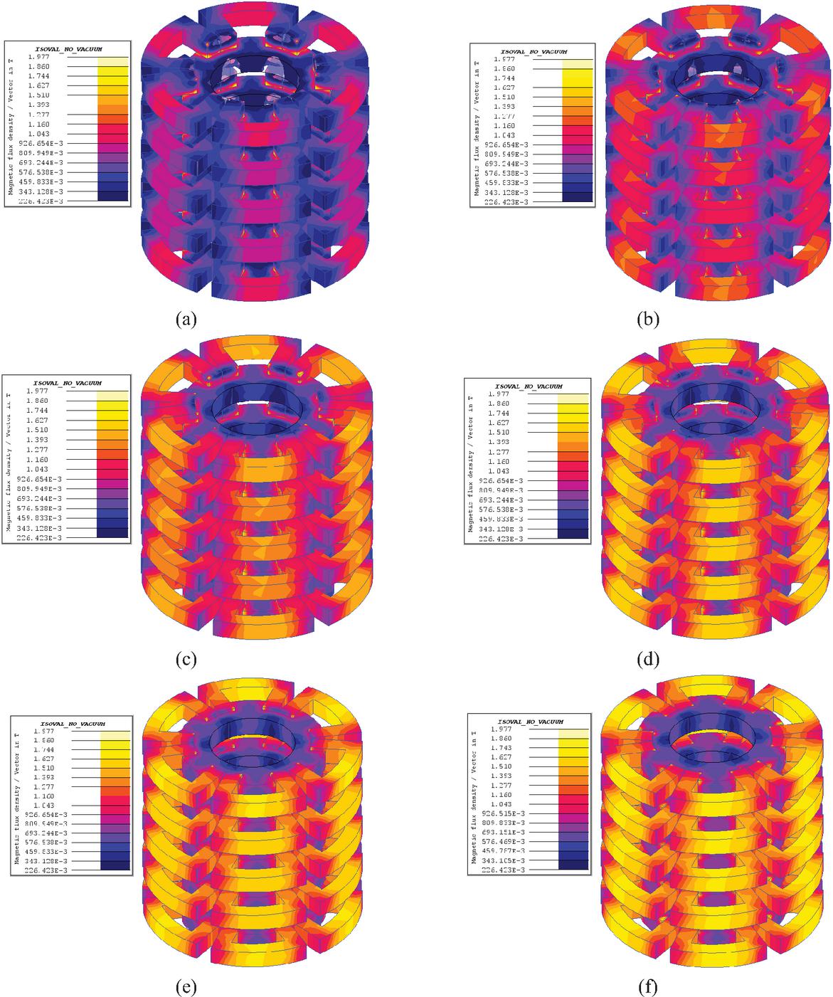
Figure 7 Magnetic flux density distribution of the 12-pole TSRLM in different mover positions: (a) 5 mm, (b) 4 mm, (c) 3 mm, (d) 2 mm, (e) 1 mm, and (f) 0 mm.
The arrow directions indicate the orientation of the magnetic flux, while the arrow colors represent the magnitude of the magnetic flux density at the corresponding mover positions. Colors closer to the top of the color scale indicate higher magnetic flux density, whereas colors closer to the bottom indicate lower magnetic flux density. As the mover travels from the 5 mm position to the 0 mm position, the magnetic flux density gradually increases. This is because, at the 0 mm position, the central axes of the stator poles and mover poles are fully aligned, and the magnetic flux lines form closed loops through the stator yoke, stator poles, mover yoke or mover poles, and the air gap, resulting in minimal leakage flux in the air. Consequently, the magnetic flux density reaches its maximum within one mover period at this position.
When the mover moves from the 0 mm position toward the 5 mm position, although the magnetic flux lines still form closed loops through the stator yoke, stator poles, mover yoke or mover poles, and the air gap, the distortion of the flux lines causes the leakage flux in the air to gradually increase. At the 5 mm or 5 mm positions, corresponding to the unaligned positions, the leakage flux reaches its maximum value.
Although the magnetic flux path distributions can clearly illustrate the flux orientation and the relative variation of magnetic flux density at different mover positions, they only provide a qualitative evaluation of the magnetic field intensity. By means of three-dimensional finite-element analysis, the magnetic flux density contour plots corresponding to an excitation current of 15 A and mover positions ranging from 5 mm to 0 mm can be obtained, as shown in Fig. 7, enabling a quantitative analysis of the magnetic flux density based on specific numerical values.
From the magnetic flux density contour plots, the saturation level of the iron core can be directly observed. The color scale associated with the contour plots indicates the magnitude of the magnetic flux density in different regions of the machine. Colors closer to the top of the scale represent higher magnetic flux density, corresponding to stronger magnetic field intensity and a higher degree of saturation, whereas colors closer to the bottom represent lower magnetic flux density, indicating weaker magnetic field intensity and a lower degree of saturation. Since the performance of SRMs can be fully exploited when operating under saturated conditions, these flux density distributions provide an effective means to assess the operating state of the machine. Based on such assessments, appropriate measures can be proposed to further enhance the performance of the machine.
As shown in Fig. 7, the relative positional relationship between the stator ferromagnetic rings and the mover ferromagnetic rings can be clearly observed at different mover positions. From the color distribution in different regions of the cross-section, it can be seen that the magnetic flux density is highest in the stator yoke, followed by the stator poles, while the magnetic flux density in the mover is comparatively lower. As the mover travels from the 5 mm position to the 0 mm position, the magnetic flux density in the ferromagnetic parts increases progressively; however, the increase in flux density is more pronounced in the stator than in the mover.
Since the 0 mm position corresponds to the aligned position, the leakage flux is minimal and the magnetic flux density reaches its maximum at this position. Nevertheless, even with the stator yoke in the 0 mm position, only a small portion of the iron core reaches a flux density of approximately 1.6 T, while most regions remain significantly unsaturated. Therefore, it can be concluded that the performance of the machine has not yet reached its optimal level, and further improvements can be achieved through appropriate optimization of the machine design.
4 SENSITIVITY-BASED SINGLE-OBJECTIVE OPTIMIZATION
In the optimization process in this paper, the single-objective optimization adopts the sensitivity analysis method. The objective function is the average electromagnetic force, and the design variables are the stator inner diameter (31-38 mm), height of the rotor magnetic pole (2–5 mm), width of the stator magnetic pole (4–5 mm), and thickness of the stator yoke (3.4–5.4 mm). By traversing the step sizes of each variable (such as 1 mm, 0.2 mm, 0.1 mm, 0.2 mm, which represent the minimum mesh length of each component, respectively), the corresponding average electromagnetic force is calculated, and the parameter corresponding to the maximum value is selected as the optimal solution.
In sensitivity analysis with average electromagnetic force as the optimization objective, the first parameter considered was the stator inner diameter, which affects the available space for winding placement. The winding space, in turn, influences the electrical loading characteristics of the motor. With all other structural parameters kept constant, the stator inner diameter was varied uniformly from 31 mm to 38 mm in 1 mm increments. During this variation, the mover’s outer diameter also changed correspondingly; the effects of the mover’s outer diameter variation and the stator inner diameter variation on motor performance can be considered equivalent. Therefore, this can be regarded as the influence of a single parameter (stator inner diameter) on electromagnetic force. A corresponding finite-element model was built to analyze this effect, and the resulting trend of the average electromagnetic force under different stator inner diameters is shown in Fig. 8.
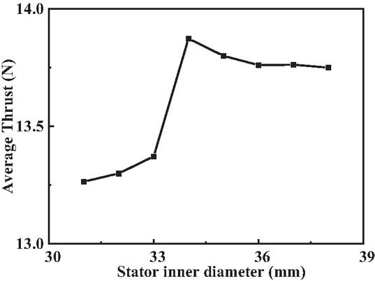
Figure 8 Average electromagnetic force under different stator inner diameters.
As shown in Fig. 8, when the stator inner diameter increases from 31 mm to 34 mm, the average electromagnetic force rises from 13.260 N to 13.875 N. This increase is attributed to shortening of the magnetic flux path as the stator inner diameter enlarges, which reduces magnetic reluctance and consequently increases the output force. When the stator inner diameter further increases from 34 mm to 38 mm, the average electromagnetic force slightly decreases from 13.875 N to 13.750 N. Throughout the entire variation range, the average electromagnetic force exhibits a small fluctuation, with a range of 0.615 N. Therefore, stator inner diameter was ultimately selected as 34 mm, corresponding to the maximum average electromagnetic force.
During sensitivity analysis of the mover pole height, the stator inner diameter of the 12-pole TSRLM finite-element model was modified to the optimized value of 34 mm, while all other structural parameters remained unchanged. Subsequently, mover pole height was varied, causing the mover yoke thickness to change correspondingly. This variation can equivalently be considered as the effect of a single structural parameter, i.e., mover pole height. Mover pole height was varied from 2 mm to 5 mm in 0.2 mm increments. The corresponding trend of average electromagnetic force with respect to mover pole height is shown in Fig. 9.
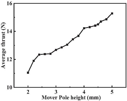
Figure 9 Average electromagnetic force with respect to mover pole height.
As shown in Fig. 9, average electromagnetic force increases with the increase of mover pole height, exhibiting a relatively steep trend. The average electromagnetic force monotonically rises from 10.701 N to 14.952 N, with a range of 4.251 N. This behavior is attributed to the increased overlap area between the stator and mover poles, which enhances the effective magnetic flux path. However, increasing the mover pole height reduces the spacing between adjacent stator poles, which complicates the manufacturing process, and an excessive pole height may also compress the stator slots, limiting the space available for winding placement. Considering these factors comprehensively, the mover pole height was ultimately set to 4.5 mm, corresponding to an average electromagnetic force of 14.21 N.
Stator pole width affects both magnetic flux density and utilization efficiency of the ferromagnetic material in the 12-pole TSRLM. During sensitivity analysis of the stator pole width, the stator inner diameter and mover pole height in the finite-element model were set to 34 mm and 4.5 mm, respectively, while all other structural parameters remained unchanged. Stator pole width was then varied from 4 mm to 5 mm in 0.1 mm increments. The corresponding trend of the average electromagnetic force with respect to stator pole width is shown in Fig. 10.
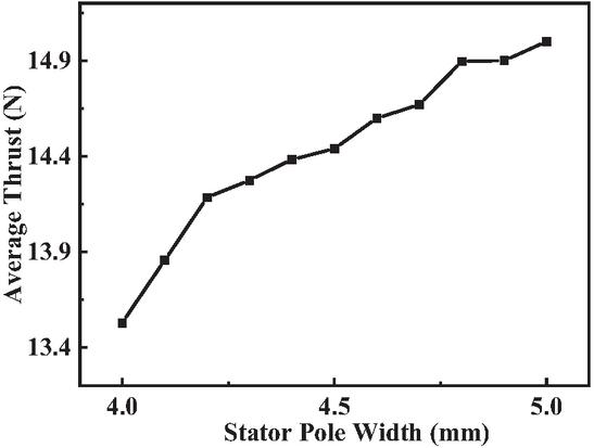
Figure 10 Average electromagnetic force with respect to stator pole width.
From Fig. 10, when the stator pole width increases from 4 mm to 4.2 mm, average electromagnetic force rises steeply from 13.561 N to 14.201 N. As the stator pole width further increases from 4.2 mm to 4.7 mm, growth of the average electromagnetic force slows down, and when the width increases from 4.7 mm to 5.0 mm, the growth trend further attenuates. Overall, the curve exhibits a monotonic trend, with a range of 1.450 N in average electromagnetic force. A stator pole width that is too small may hinder the formation of an effective magnetic path, whereas an excessively large width reduces the spacing between the winding and adjacent poles, significantly increasing manufacturing difficulty. Moreover, an oversized stator pole width constrains the size of the stator slots, limiting the space available for winding placement. Considering these factors comprehensively, stator pole width was ultimately determined to be 4.8 mm.
Similar to stator pole width, the stator yoke thickness also affects formation of the effective magnetic circuit. During sensitivity analysis of the stator yoke thickness, the stator inner diameter, mover pole height, and stator pole width in the finite-element model were set to 34 mm, 4.5 mm, and 4.8 mm, respectively. All other structural parameters were kept constant, while the stator yoke thickness was varied from 3.4 mm to 5.4 mm with a step size of 0.2 mm. The corresponding trend of the average electromagnetic force with respect to the stator yoke thickness is shown in Fig. 11.
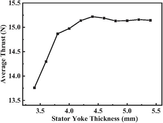
Figure 11 Average electromagnetic force with respect to stator yoke thickness.
As shown in Fig. 11 when stator yoke thickness increases from 3.4 mm to 4.4 mm, the average electromagnetic force exhibits a relatively steep increase, rising from 13.751 N to 15.201 N. When yoke thickness further increases from 4.4 mm to 5.4 mm, the growth of the average electromagnetic force becomes much more gradual, approaching an almost constant value. The range of the average electromagnetic force is 1.480 N. An excessively thick stator yoke compresses the stator slot size, reducing the space available for winding placement, and may also prevent the core from reaching magnetic saturation, which increases the motor mass and leads to underutilization of the core, ultimately degrading motor performance. Considering these factors comprehensively, stator yoke thickness was finally selected as 4.4 mm. The structural parameters after single objective optimization are presented in Table 1.
Table 1 Structural parameters of 12-pole TSRLM
| Structural | Size | Structural | Size |
| Parameter | Parameter | ||
| Stator outer diameter | 63.0 mm | Mover yoke thickness | 4.5 mm |
| Stator inner diameter | 34.0 mm | Mover pole height | 4.5 mm |
| Mover outer diameter | 42.6 mm | Stator spacing ring thickness | 8.0 mm |
| Shaft diameter | 24.6 mm | Mover ferromagnetic ring thickness | 5.5 mm |
| Stator yoke thickness | 4.4 mm | Mover spacing ring thickness | 7.5 mm |
| Stator pole width | 4.8 mm | Air-gap length | 0.2 mm |
| Stator ferromagnetic ring thickness | 5.0 mm | Mover stack length | 65.0 mm |
| Stator module angle | 43/2∘ |
Figure 12 shows the output electromagnetic force waveforms of the 12-pole TSRLM before and after optimization. It can be observed that the optimized TSRLM exhibits a significant improvement in output electromagnetic force compared with the pre-optimization design. Calculations indicate that the average electromagnetic force over half a mover pole pitch increased from 12.73 N before optimization to 14.69 N after optimization, representing a 15.4% improvement. This result demonstrates the effectiveness of the single-objective optimization.
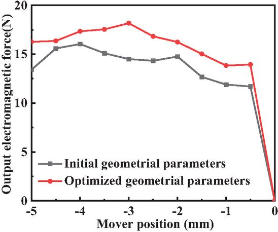
Figure 12 Comparison curves of output electromagnetic force of the 12-pole TSRLM before and after single objective optimization.
5 EXPERIMENTAL VERIFICATION
A prototype of the 12-pole TSRLM after single-objective optimization was fabricated, and both the hardware test bench and the machine test platform were designed and established, as shown in Fig. 13. In this system, a DC rotary motor is used as the prime mover. Its torque is regulated by the magnetic powder brake, and the rotary motion is converted into reciprocating linear motion through a crank-slider mechanism connected to the TSRLM mover, thereby driving the TSRLM to operate under reciprocating motion.
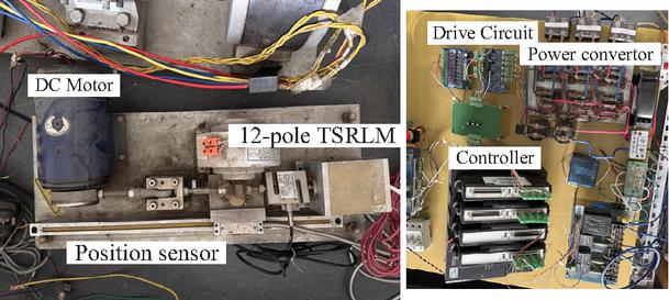
Figure 13 The 12-pole TSRLM and hardware experiment platform.
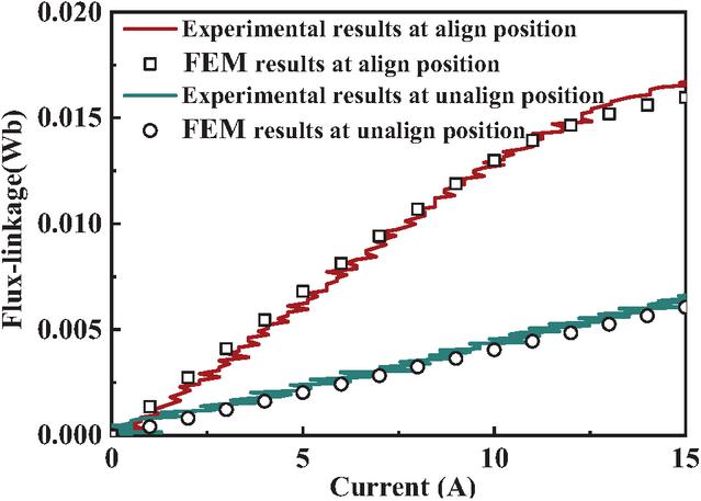
Figure 14 Comparison of magnetization curves at special mover positions.
Based on the hardware experimental platform described above, static tests were conducted on the proposed 12-pole TSRLM. The static tests include static flux linkage measurements as well as voltage and current measurements. During the static flux linkage test, the mover of the machine was fixed at the aligned position (0 mm) and the unaligned positions (5 mm or 5 mm), respectively. A 12-V phase voltage was then instantaneously applied to the phase winding of the TSRLM, and the corresponding voltage and current waveforms were recorded. The measured voltage and current data were processed, and the flux linkage was calculated using the known voltage balance equation.
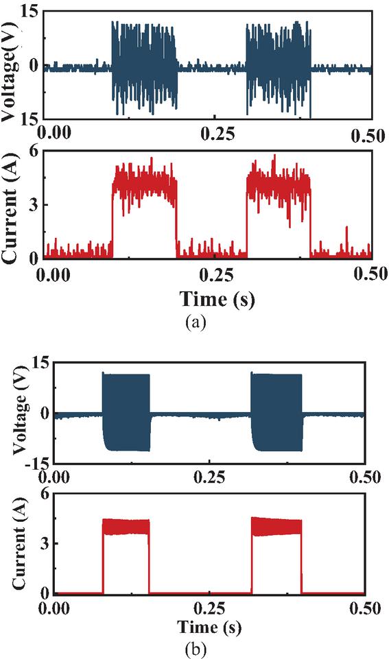
Figure 15 Comparison of experiment and simulation under 4 A current chopping limit: (a) experimental curve under 4 A current chopping limit and (b) simulation curve under 4 A current chopping limit.
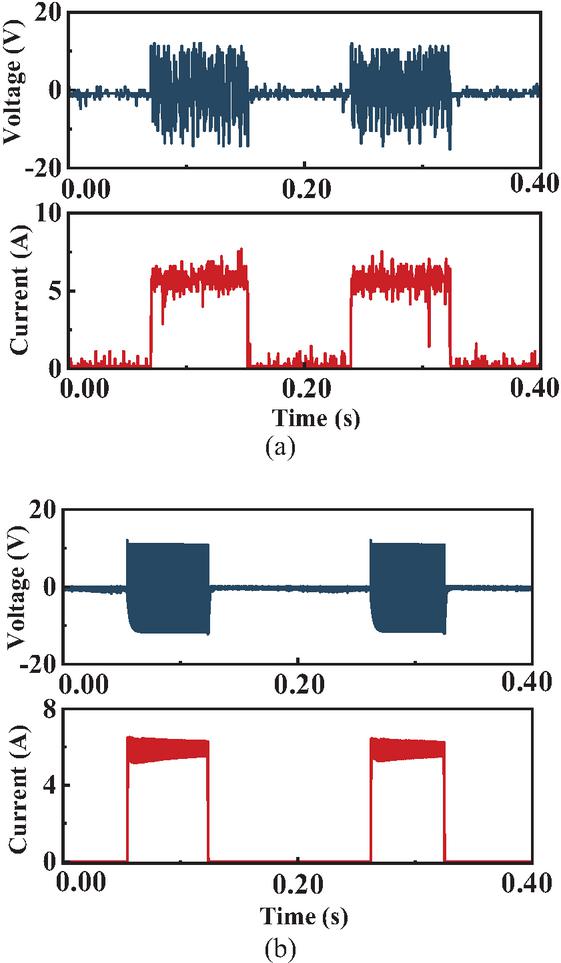
Figure 16 Comparison of experiment and simulation under 6 A current chopping limit: (a) experimental curve under 6 A current chopping limit and (b) simulation curve under 6 A current chopping limit.
Comparison between the experimental results and the finite-element calculation results is shown in Fig. 14. It can be observed that the experimentally obtained magnetization curves agree well with those predicted by finite-element analysis, with a discrepancy of less than 5%. In the high-current region, the flux linkage values obtained from the finite-element model are slightly lower than the experimental results. This discrepancy may be attributed to the neglect of leakage flux caused by longitudinal end effects in the finite-element model, which leads to an underestimation of the magnetization curves at both aligned and unaligned positions. In addition, manufacturing tolerances and assembly imperfections may also contribute to the observed differences.
Dynamic tests were carried out on the 12-pole TSRLM prototype, which also served to verify the accuracy of the MATLAB/Simulink dynamic simulation model. The DC supply voltage was set to 12 V, and a current chopping control strategy was adopted. The current chopping limits were set to 4 A and 6 A, respectively, and the corresponding winding voltage and winding current waveforms were measured. Using the same control strategy and identical current chopping limits, the winding voltage and current waveforms were obtained from the MATLAB/Simulink dynamic simulation model. Comparisons between the measured and simulated waveforms are presented in Figs. 15 and 16.
From the comparison results, it can be observed that the measured waveforms agree well with the simulated ones. As the current chopping limit increases, the winding current increases accordingly, leading to a higher output electromagnetic force. Consequently, the operating speed of the 12-pole TSRLM also increases. The motoring performance tests not only validate the dynamic performance of the TSRLM prototype but also confirm the accuracy and effectiveness of the finite-element analysis and dynamic simulation models.
6 CONCLUSION
This paper presents a modular transverse-flux tubular switched reluctance linear machine based on U-shaped stator topology. The proposed modular structure effectively shortens magnetic flux paths and enhances iron core utilization, resulting in improved electromagnetic characteristics. A three-dimensional finite-element analysis is performed to investigate the electromagnetic behavior of the machine, and a simple single-objective optimization is employed to enhance the average electromagnetic force. A 12-pole TSRLM prototype is manufactured and experimentally tested. The close agreement between experimental and simulation results confirms the correctness of the electromagnetic modeling and the feasibility of the proposed machine design. With its modular structure, simple configuration, and good manufacturability, the proposed TSRLM provides a promising solution for high-performance linear electric drive applications.
ACKNOWLEDGMENTS
This work is supported by the National Natural Science Foundation of China International (regional) co-operation and exchange projects NSFC-RSF under Grant W2412064.
REFERENCES
[1] H. Chen, J. Liu, C. Liu, X. Wang, A. Musolino, M. Shamiyev, and A. O. Pulatov, “A novel tubular double stator switched reluctance linear launcher,” IEEE T. Plasma Sci., vol. 53, no. 10, pp. 2677–2681, Oct. 2025.
[2] J. Liu, H. Chen, X. Wang, P. Wheeler, V. F. Pires, J. F. A. Martins, A. Musolino, Y. Gorbounov, and H. Torkaman, “Switched reluctance linear motor force ripple suppression based on fixed frequency implicit generalized predictive self-correction controller,” IEEE Transactions on Energy Conversion, pp. 1–18, 2024.
[3] Q. Sun, J. Wu, and C. Gan, “Optimized direct instantaneous torque control for SRMs with efficiency improvement,” IEEE Transactions on Industrial Electronics, vol. 68, no. 3, pp. 2072–2082, Mar. 2021.
[4] R. Yang, X. Wang, Z. Huang, and Y. Ma, “Torque ripple minimization control of switched reluctance motor based on online torque sharing function,” IEEE Transactions on Power Electronics, vol. 40, no. 4, pp. 4878–4888, 2025.
[5] J. Cai, X. Dou, A. D. Cheok, W. Ding, Y. Yan, and X. Zhang, “Model predictive control strategies in switched reluctance motor drives – An overview,” IEEE Transactions on Power Electronics, vol. 40, no. 1, pp. 1669–1685, 2025.
[6] S. Tavakolian, G. Fang, S. Dhale, and B. N. Mobarakeh, “Fixed-switching model-free predictive current control of switched reluctance motor using parameter estimation,” in 2024 IEEE Transportation Electrification Conference and Expo (ITEC), 2024.
[7] A. Walz-Lange and G. Schullerus, “Sensorless control of a switched reluctance machine based on switching frequency evaluation,” IEEE Transactions on Industry Applications, vol. 58, no. 4, pp. 4768–4777, 2022.
[8] R. Nie, H. Chen, J. Liu, W. Zhao, S. Zhao, J. Tian, X. Wang, and Y. Huo, “Peak current compensation for reducing the negative impact of LEE on SRLM,” IET Electric Power Applications, vol. 14, no. 6, pp. 1030–1040, June 2020.
[9] H. Chen, R. Nie, J. Liu, W. Zhao, Z. Yuan, and J. Tian, “A novel tubular switched reluctance linear machine shielding from longitudinal end magnetic effect,” IEEE Transactions on Applied Superconductivity, vol. 30, no. 4, pp. 1–7, 2020.
[10] D. Wang, C. Shao, and X. Wang, “Design and performance evaluation of a tubular linear switched reluctance generator with low cost and high thrust density,” IEEE Transactions on Applied Superconductivity, vol. 26, no. 7, pp. 1–5, 2016.
[11] D. Wang, D. Zhang, X. Du, and X. Wang, “Unitized design methodology of linear switched reluctance motor with segmental secondary for long rail propulsion application,” IEEE Transactions on Industrial Electronics, vol. 65, no. 12, pp. 9884–9894, 2018.
[12] W. Ding, Y. Hu, T. Wang, and S. Yang, “Comprehensive research of modular e-core stator hybrid-flux switched reluctance motors with segmented and nonsegmented rotors,” IEEE Transactions on Energy Conversion, vol. 32, no. 1, pp. 382–393, 2017.
[13] W. Ding, Y. Hu, Q. Ze, X. Liu, and Y. Liu, “A novel modular E-core stators and segmental rotors switched reluctance machine for electric vehicles,” in 2014 Ninth International Conference on Ecological Vehicles and Renewable Energies (EVER), pp. 1–8, 2014.
[14] M. Ruba, I. Benþia, and L. Szabó, “Modular fault tolerant switched reluctance machine-design and dynamic simulations,” in 12th International Conference on Optimization of Electrical and Electronic Equipment, pp. 441–446, 2010.
BIOGRAPHIES

Hao Chen received the B.S. and Ph.D. degrees in electrical engineering from the Department of Automatic Control, Nanjing University of Aeronautics and Astronautics, Nanjing, China, in 1991 and 1996, respectively. He is with the School of Electrical and Power Engineering, China University of Mining and Technology, Xuzhou, where he has been a professor since 2001. From 2002 to 2003, he was a Visiting Professor with Kyung sung University, Busan, South Korea. Since 2008, he has also been an Adjunct Professor with The University of Western Australia, Perth, WA, Australia. He has authored one book and more than 200 articles. He holds 15 U.S. patents, 23 Australian patents, one Danish patent, seven Canadian patents, three South African patents, 10 Russian patents, 66 Chinese invention patents, and six Chinese utility model patents. His current research interests include motor control, linear launcher, electric vehicles, electric traction, servo drives, and wind power generator control. Chen was a recipient of the Prize of Science and Technology of Chinese Youth and the Prize of the Fok Ying Tong Education Foundation for Youth Teachers in 2004. He was awarded the First Prize in the Science and Technology Advanced of Province and Ministry once, the Second Prize in the Science and Technology Advanced of Province and Ministry nine times, and the Third Prize in the Science and Technology Advanced of Province and Ministry 14 times. He became the Chinese New Century Hundred-Thousand Ten-Thousand Talents Engineering National Talent in 2007, and won the Government Especial Allowance of People’s Republic of China State Department in 2006.

Denis Kotin received the B.S., M.S., and Cand. Tech. Sc. in the Department of Electric Drive and Industry Automation, Faculty Mechatronics and Automation, Novosibirsk State Technical University, Russia, in 2005, 2007, and 2010, respectively. Since 2015, is the Head of the Department of Electric Drive and Industry Automation. Research interests include automatic control of AC electric drives and power electronic devices, and he has authored more than 160 scientific publications.

Aris Dimeas is an Assistant Professor at the School of Electrical and Computer Engineering of the National Technical University of Athens (NTUA), with more than 20 years of experience in power systems operation, smart grids, and energy system digitalization. His expertise spans distribution and transmission system operation, renewable energy integration, microgrids, flexibility markets, artificial intelligence applications, and advanced control and decision-support software. He has played a leading technical and coordination role in more than 30 EU-funded research and innovation projects (H2020 and Horizon Europe), collaborating closely with TSOs, DSOs, regulators, industry, and the European Commission. His work bridges research and real-world deployment, with demonstrated impact on system supervision, resilience, market design, and data-driven grid operation, while his scientific contributions include high-impact publications in leading IEEE and international journals.

Emmanuel Karapidakis is an Electrical and Computer Engineer. He was Dean at School of Engineering from 2019 to 2025, and Director of Energy, Environment and Climate Change Institute IEECC, in Hellenic Mediterranean University HMU. Since 2022, he is President of the Board in Hellenic Association of Electricity Storage Systems HAESS. His research interests focus on energy systems, power systems operation, diverse & dispersed generation, micro-grids, renewable energy technologies, energy storage, and energy markets. He is/was scientific coordinator (PI) in 12 European financed projects, 15 National programs, and several private funded projects, with more than 8 million euros in total. He has published more than 120 papers (Scopus Author ID 6506872824) in prestigious journals and scientific conferences, and four scientific book chapters. From 2011 to 2015, he was Member of the Board in Regional Council of Innovation, and from 2015 to 2017, Member of Board in Energy Planning Council at Region of Crete.

Olimjon Toirov received his Ph.D. (2012) and D.Sc. (2018) in Technical Sciences (Energy Systems and Complexes) from the Institute of Energy and Automation, Academy of Sciences of Uzbekistan, and Tashkent State Technical University (TSTU), respectively. He was awarded the academic title of Full Professor in 2020. He has held research and leadership positions at the Institute of Energy and Automation, Uzbekenergo, AGH University of Science and Technology (Poland), and TSTU, where he served as Head of the Electrical Machines and Drives Department (2019–2024) and has been Dean of the Faculty of Electrical Engineering since 2024. His research interests include electric drive systems, renewable and green energy, energy efficiency, asynchronous generator control, and electromechanical system optimization. He has led and participated in over 65 industrial and research projects, implemented control systems in major industrial enterprises, and received more than 12 international research grants. Toirov has authored over 300 publications, including patents, textbooks, and monographs, with more than 40 papers indexed in Web of Science and Scopus. He has supervised one D.Sc., five Ph.D., and numerous undergraduate and master’s students. His honors include national scientific awards, the Scopus Uzbekistan Award (2023), and the Shuhrat medal (2024). He currently serves on national expert councils and editorial boards of scientific journals.

Liu Jingfu received the B.S. degree in Mechanical and Electrical Engineering, from Northeast Forestry University, Harbin, Heilongjiang, China, in 2017, the M.S. degree from the School of Electrical Engineering, China University of Mining and Technology, Xuzhou, Jiangsu, in 2021. He is currently pursuing a Ph.D. degree in electrical engineering at China University of Mining and Technology, Xuzhou. His research interests include switched reluctance linear motor control, ocean wave power generation, and electric vehicles.

Zhao Wenmin received the B.S. degree in automation from the Taiyuan University of Technology, Taiyuan, China, in 2017. She is currently pursuing the master’s degree in electrical engineering with the China University of Mining and Technology, Xuzhou. Her current research interests include motor design and optimization.

Xing Wang received the B.S. degree from China University of Mining and Technology, Xuzhou Jiangsu, China, in 1996, and M.S. degree from China University of Mining and Technology, Xuzhou Jiangsu, in 1999. In 2007, she became an Associate Professor with China University of Mining and Technology, Xuzhou. She is a holder of four US Patents, nine Australian Patents, two Canadian Patents, four Russian Patents, 12 Chinese Invention Patents, three Chinese Utility Model Patents, and has authored 15 papers.

Sherif Moussa is Dean of the School of Engineering, Applied Science, and Technology at the Canadian University Dubai (CUD), UAE. He earned his Ph.D. in Electrical and Computer Engineering from the University of Québec at Trois-Rivières, Canada, and his M.Sc. in Electrical and Computer Engineering from the University of Waterloo, Canada. Since joining CUD in 2007, Moussa has led the School’s remarkable growth, overseeing the launch and accreditation of several engineering and computing programs, including Mechatronics Engineering, Computer Science, Cybersecurity, Software Design, Power and Renewable Energy Engineering, and the M.Sc. in Artificial Intelligence. His leadership has also advanced international collaborations, notably with Queen’s University and the University of Ottawa, and strengthened CUD’s engagement with industry partners in emerging technologies. Moussa’s research interests span wireless communication, computer networks, machine learning, and digital systems design. He has published widely in international journals and conferences, serves on technical committees, and is the recipient of the 2015 CUD Research Excellence Award. He is also the founder of CUD’s Robotics Club and a strong advocate for innovation and experiential learning in engineering education.
ACES JOURNAL, Vol. 41, No. 6, 536–550
DOI: 10.13052/2026.ACES.J.410605
© 2026 River Publishers