Performance Comparison Analysis of Modular Double-Stator Switched Reluctance Motor with Differing Winding Polarities
Fengyuan Yu1, 5, Hao Chen1, 2, 3,*, Haidong Yan4, Guanjun Wang4, and Jun Bao4
1School of Electrical Engineering China University of Mining and Technology, Xuzhou 221116, China
fyyu@cumt.edu.cn, hchen@cumt.edu.cn
2International Joint Research Center of Central and Eastern European Countries on New Energy Electric Vehicle Technology and Equipment Xuzhou 221008, China
3Shenzhen Research Institute China University of Mining and Technology, Shenzhen 518057, China
4Wuxi Institute of Inspection, Testing and Certification Wuxi 214101, China
yhd@wxmtc.com, wgjcumt@126.com, jsmtc12@126.com
5School of Electrical Engineering and Automation Jiangsu Normal University, Xuzhou 221116, China
∗Corresponding author
Submitted On: February 11, 2026
Accepted On: July 30, 2026
ABSTRACT
Modular double-stator switched reluctance motors offer the advantages of high torque density, low mutual coupling, and high reliability, making them promising candidates for electrified transportation applications. The dual-winding configuration enables both the inner and outer stator poles to be equipped with excitation windings. Variations in the excitation direction of these windings lead to distinct winding polarity distributions, thereby resulting in different magnetic flux paths and electromagnetic characteristics. This paper presents two typical polarity distributions for modular double-stator switched reluctance motors, namely NSNS and NSSN. Motor models are established in the finite element software Altair Flux to analyze the flux path, flux density, and static electromagnetic torque under both winding polarities. In addition, dynamic performance metrics including torque ripple, core loss, copper loss, and efficiency are evaluated under various rotor geometries and operating speeds. The influence of key rotor geometric parameters on the torque and efficiency characteristics of the two polarity configurations is also investigated.
Keywords: Electromagnetic performance, finite element analysis, flux path, switched reluctance motor, winding polarity..
1 INTRODUCTION
Owing to the absence of permanent magnet and windings on the rotor, the switched reluctance motor (SRM) boasts advantages such as simple and robust construction, low manufacturing cost, and strong fault tolerance [1, 2]. Consequently, it has found applications in various fields including electric vehicles, electric aircraft, and wind power generation [3, 4]. However, due to its inherent reluctance torque nature, the torque and power performance of SRMs still lag behind those of permanent magnet motors and require improvement.
To enhance SRMs’ performance, several novel motor structures, including double-stator SRM [5], segmentedrotor SRM [6], axial-flux SRM [7], and hybrid excitation SRM [8] configurations have been proposed. Among these, the double-stator SRM (DSSRM) improves the utilization of electromagnetic space and is characterized by high torque density. Nevertheless, the design process of its structural parameters often involves large phase inductance values or a high ratio of maximum to minimum inductance. The traditional SRM features a fixed magnetic circuit and a single operational mode. This often results in a limited constant-power speed range and a restricted operational region for DSSRMs, even when they possess high torque density characteristics. It is challenging to achieve both high torque density and a wide speed range simultaneously, which limits their application in scenarios demanding non-rare-earth motor systems that combine these two features.
In other types of motors, variable-flux motor structures have become a current research hotspot. Variable-flux motors enhance field-weakening capability, broaden the constant-power range, and enable wide-speed operation by introducing an additional controllable magnetic flux regulation variable to alter the main air-gap flux. Depending on the method of air-gap flux regulation, adjustable-flux motors include hybrid excitation, mechanical flux adjustment, variable stator winding configuration, and variable flux memory motors [9, 10, 11, 12]. For SRMs, some scholars have achieved flux regulation by employing two separate sets of windings simultaneously. This approach aims to extend the motor’s speed range while maintaining torque output capability at low speeds [13, 14, 15, 16]. However, this scheme faces shortcomings such as a high slot fill factor, severe electromagnetic coupling, and complex decoupling control, which hinder the widespread adoption of this motor type.
Indeed, varying the energizing direction of the winding coils leads to distinct winding polarity distributions, which in turn affect motor performance. This paper investigates the influence of the winding coil energizing direction on the performance of modular DSSRMs. First, the motor structure is described and the feasible polarity configurations are identified. Second, a two-dimensional finite element model of the motor is developed in finite element software, and the flux paths, flux density, torque, flux linkage, and inductance characteristics under the two different winding polarities are analyzed using the finite element analysis method. Finally, the effect of rotor pole arc angle on the torque characteristics of the motors with the two polarity distributions is examined.
2 MOTOR STRUCTURE AND WINDING POLARITY DISTRIBUTION
Figure 1 illustrates the structural schematic of the modular double-stator switched reluctance motor. As can be observed, the inner stator, rotor, and outer stator are concentrically arranged from the innermost to the outermost layers. Both the inner and outer stators adopt the U-shaped modular structure, positioned on either side of the segmented rotor, which itself features a sector-shaped modular configuration. A total of eight U-shaped outer stator modules, eight U-shaped inner stator modules, and 14 sector-shaped rotor segments are uniformly distributed along the circumferential direction. The tooth poles of both the inner and outer U-shaped stators face the rotor. The pole numbers of the inner stator, rotor, and outer stator are 16, 14, and 16, respectively.
In addition, each tooth pole of both the outer and inner stators is equipped with excitation windings. It is worth noting that by varying the energizing directions of the excitation windings on the inner and outer stators, different polarity distribution characteristics can be achieved in the modular double-stator switched reluctance motor. In this paper, a single stator unit is formed by combining one U-shaped outer stator, the corresponding U-shaped inner stator positioned opposite to it, and the surrounding segmented rotor. When the excitation windings on the inner and outer stators are energized in the same direction, the polarity distribution of a single stator unit is NSNS.
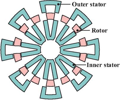
Figure 1 Diagram of the modular double-stator switched reluctance motor structure.
Figure 2 presents a schematic diagram of the winding energizing directions for both the entire motor cross-section and a single stator unit under the NSNS polarity distribution. It can be observed that the tooth polarities of the outer U-shaped stator from left to right are N and S, while those of the inner U-shaped stator from left to right are also N and S. This indicates that the energizing direction of the excitation windings on the inner stator is identical to that on the outer stator.
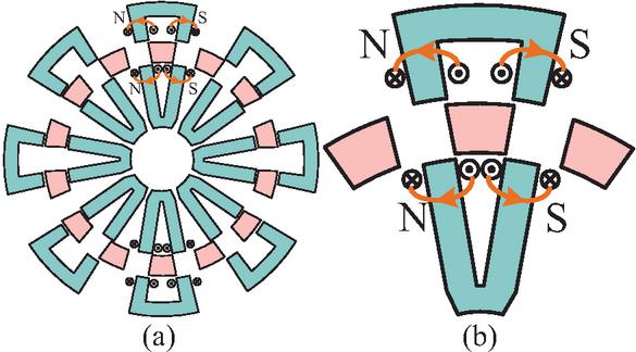
Figure 2 Diagram of winding coil connection under NSNS polarity distribution: (a) cross-sectional view of the whole motor and (b) single inner/outer stator unit.
As can be seen, when the excitation windings on the inner and outer stators are energized in the same direction, corresponding to the NSNS polarity distribution, the magnetic flux forms a closed loop along the adjacent segmented inner stator teeth, segmented rotor, and segmented outer stator teeth, resulting in a relatively long flux path. Figures 3 (a) and (b) depict the flux paths at the rotor fully aligned and fully unaligned positions, respectively, under this polarity, with arrows indicating the direction of magnetic flux.
As shown in Fig. 3 (a), when the motor is at the rotor unaligned position under the NSNS polarity, the magnetic flux circulates through the segmented inner stator teeth, the air gap between two adjacent segmented rotor segments, and the segmented outer stator teeth, forming a closed annular loop. At this position, the motor exhibits the minimum inductance under this polarity. In contrast, Fig. 3 (b) illustrates that when the motor is at the rotor aligned position under the NSNS polarity, the magnetic flux flows through the segmented inner stator teeth, two adjacent segmented rotor segments, and the segmented outer stator teeth, again forming a closed annular loop. This corresponds to the position of maximum inductance under this polarity.
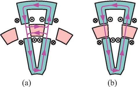
Figure 3 Diagram of the flux path under NSNS polarity distribution: (a) rotor electromagnetic unalignment position and (b) rotor electromagnetic alignment position.
When the excitation windings on the inner and outer stators are energized in opposite directions, the polarity distribution of a single stator unit becomes NSSN. A schematic representation of the winding energizing directions for both the full motor cross-section and a representative stator unit under the NSSN configuration is provided in Fig. 4.
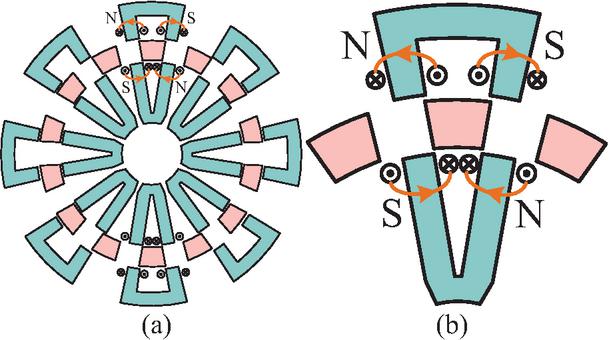
Figure 4 Diagram of winding coil connection under NSSN polarity distribution: (a) cross-sectional view of the whole motor and (b) single inner/outer stator unit.
As evident, the outer U-shaped stator teeth exhibit N and S polarities from left to right, while the inner U-shaped stator teeth display S and N polarities in the same orientation. This indicates that the excitation windings on the inner and outer stators are energized in opposite directions. By reversing the current direction in the inner stator windings, the proposed variable-flux-path double-stator switched reluctance motor can realize distinct magnetic flux path configurations. Under the NSSN polarity distribution, where the inner and outer stator excitations are opposing, the magnetic flux completes a closed loop via the adjacent segmented inner stator tooth, the segmented rotor, and the segmented outer stator tooth, forming a relatively short flux path. The flux path distributions at the fully aligned and fully unaligned rotor positions for this polarity are presented in Figs. 5 (a) and (b), respectively.
Figure 5 (a) reveals that at the unaligned position under NSSN polarity, the magnetic flux emanates separately from the segmented inner and outer stator teeth and cancels within the segmented rotor, thereby establishing a closed circuit. This rotor position yields the minimum inductance for this polarity. In contrast, Fig. 5 (b) shows that at the aligned position under NSSN polarity, the flux flows from the segmented inner stator tooth, through the segmented rotor, and into the segmented outer stator tooth, subsequently canceling within the rotor to close the loop. This electromagnetic alignment position corresponds to the maximum inductance condition under the NSSN polarity.
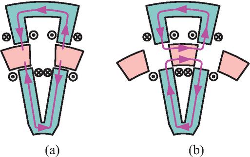
Figure 5 Diagram of the flux path under NSSN polarity distribution: (a) rotor electromagnetic unalignment position and (b) rotor electromagnetic alignment position.
A comparative look at Figs. 3 and 5 reveals that, without any modification to the stator or rotor structure, simply altering the excitation direction of the inner stator windings enables two distinct magnetic flux paths. This difference in flux routing gives rise to varying electromagnetic characteristics, which will be examined in detail via finite element analysis in the following section. It is worth noting that SNSN and SNNS represent additional feasible winding polarity configurations. However, since SNSN produces magnetic circuit behavior equivalent to that of NSNS, and SNNS mirrors the effect of NSSN, these two distributions are not addressed in the present study.
3 FINITE ELEMENT MODELLING AND STATIC ELECTROMAGNETIC PERFORMANCE ANALYSIS
To evaluate the performance of the modular double-stator switched reluctance motor under different winding polarity distributions, a two-dimensional finite element model was developed using the commercial simulation software Altair Flux 2020. The established finite element model and its corresponding meshing results are depicted in Fig. 6. Furthermore, the stator and rotor cores are fabricated from 50DW470 silicon steel sheets. The key structural parameters of the motor prototype are summarized in Table 1.
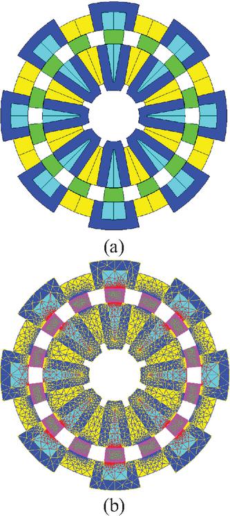
Figure 6 Comparison of non-eccentric and static eccentric structures.
The static magnetic flux line and flux density behaviors are examined first. With the excitation magnetomotive force set to 900 ampere-turns and the excitation direction of the inner and outer stator windings set to be identical, the flux line distributions at the rotor unaligned and aligned positions under the NSNS polarity are reported in Fig. 7. Figure 8 offers the corresponding flux density contour maps for these two rotor positions.
As can be seen from Fig. 7, when the motor operates under the NSNS polarity configuration, a closed long flux loop is formed along the inner U-shaped segmented stator, two adjacent segmented rotor blocks, and the outer U-shaped segmented stator at the rotor aligned position, i.e., the maximum inductance position. A similar closed long loop is likewise observed at the minimum inductance position. The flux density contours presented in Fig. 8 are consistent with the flux line distributions, further confirming this behavior. These findings demonstrate that when the inner and outer stator windings are energized in the same direction, the magnetic flux path within each stator unit assumes a closed annular shape.
Table 1 Parameters of the modular double-stator switched reluctance motor
| Motor Parameter | Unit | Value |
| Outer stator poles number | / | 16 |
| Inner stator poles number | / | 16 |
| Rotor poles number | / | 14 |
| Outer stator outer diameter | mm | 200 |
| Rotor outer diameter | mm | 151 |
| Inner stator outer diameter | mm | 126 |
| Outer stator yoke thickness | mm | 9 |
| Inner stator yoke thickness | mm | 7 |
| Outer stator pole arc angle | 7 | |
| Inner stator pole arc angle | 7 | |
| Rotor pole arc angle | 14 | |
| Air-gap length | mm | 0.5 |
| Stacking length | mm | 100 |
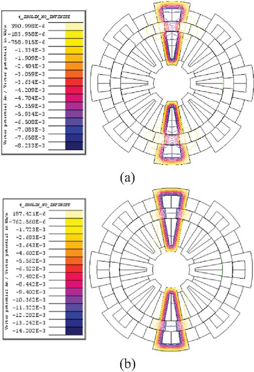
Figure 7 Magnetic lines distribution at rotor special positions under NSNS polarity distribution: (a) rotor electromagnetic unalignment position and (b) rotor electromagnetic alignment position.
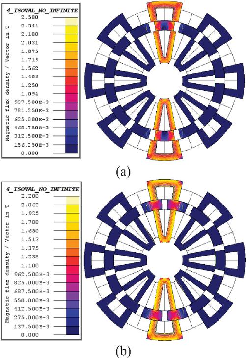
Figure 8 Magnetic density maps at rotor special positions under NSNS polarity distribution: (a) rotor electromagnetic unalignment position and (b) rotor electromagnetic alignment position.
Additionally, by reversing the excitation directions of the inner and outer stator windings while maintaining the same magnetomotive force of 900 AT, the motor operates under the NSSN polarity distribution. Figure 10 exhibits the corresponding flux density contour maps at these two specific rotor positions.
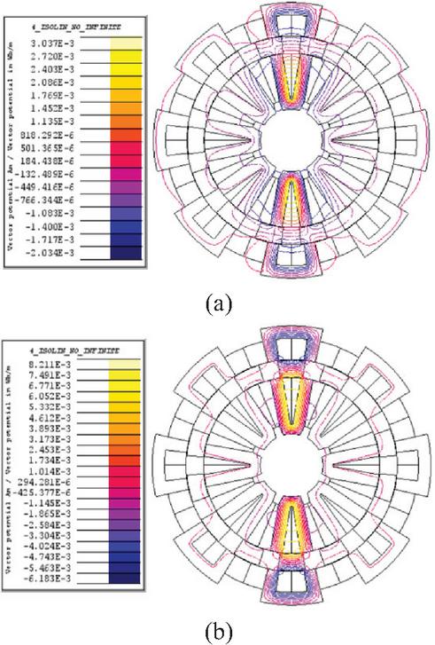
Figure 9 Magnetic lines distribution at rotor special positions under NSSN polarity distribution: (a) rotor electromagnetic unalignment position and (b) rotor electromagnetic alignment position.
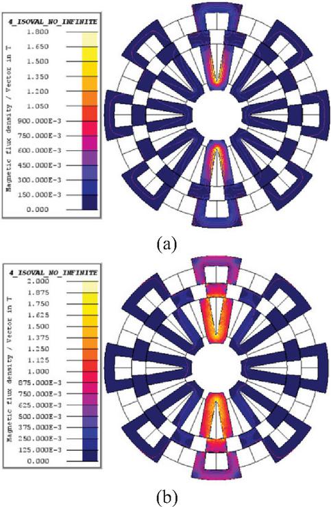
Figure 10 Magnetic density maps at rotor special positions under NSSN polarity distribution: (a) rotor electromagnetic unalignment position and (b) rotor electromagnetic alignment position.
As revealed in Fig. 9, under the NSSN polarity configuration, a closed short flux loop is formed at the rotor aligned position, i.e., the maximum inductance position, with magnetic flux traveling along the inner U-shaped segmented stator, the segmented rotor, and the outer U-shaped segmented stator, ultimately canceling within the segmented rotor. A similar closed short loop, also characterized by flux cancellation within the segmented rotor, is observed at the minimum inductance position. The flux density contours in Fig. 10 further corroborate these findings. This confirms that when the inner and outer stator windings are energized in opposite directions, the magnetic flux paths cancel each other within the intermediate segmented rotor of each stator unit. Then, the static electromagnetic torque characteristics of the motor are subsequently evaluated. In the finite element simulation, a fixed current was injected into phase A, with the excitation magnitude progressively increased from 20 A to 100 A, while the rotor position was swept from 0 to 180 electrical degrees. The resulting static torque profiles under the NSNS and NSSN polarity distributions are presented in Fig. 11. It can be observed that electromagnetic torque is generated under both winding polarity configurations; however, the torque waveforms exhibit distinct shapes.
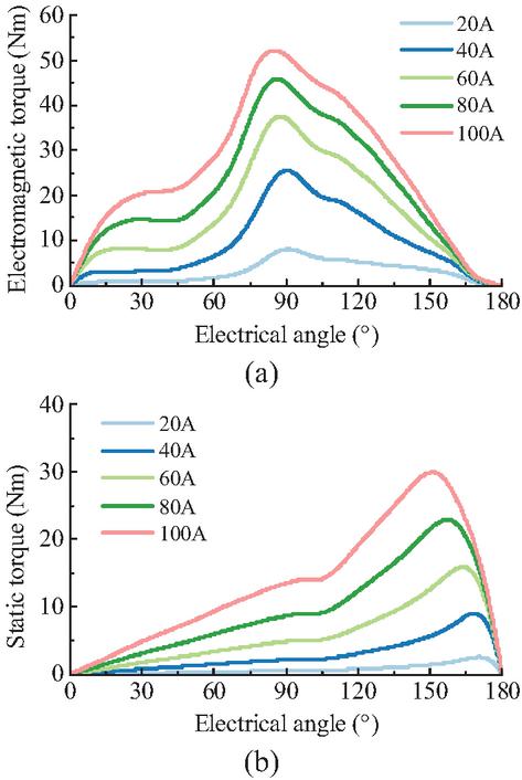
Figure 11 Static torque waveforms of the motor in two winding polarity arrangement: (a) NSNS and (b) NSSN.
Table 2 Average torque values of the motor in two winding polarity arrangement
| Winding Polarity | NSNS | NSSN |
| 20 A | 02.893 Nm | 00.723 Nm |
| 40 A | 09.074 Nm | 02.757 Nm |
| 60 A | 15.154 Nm | 05.642 Nm |
| 80 A | 20.476 Nm | 09.144 Nm |
| 100 A | 25.027 Nm | 13.035 Nm |
To quantitatively assess the static torque output, the average torque values were computed and are summarized in Table 2. The results indicate that, under the current electromagnetic dimensions, the static electromagnetic torque produced by the NSNS polarity consistently exceeds that of the NSSN polarity, irrespective of the applied excitation current level.
It should be noted that the consistently lower static torque output of the NSSN configuration observed in Fig. 11 and Table 2 is obtained under the baseline rotor pole arc angle of 14∘. Under this geometry, the short flux path characteristic of the NSSN arrangement forces the magnetic flux to concentrate within a limited rotor region at the electromagnetically aligned position, as illustrated in Figs. 9 and 10. As the excitation current increases, this localized flux concentration causes the rotor segments to saturate more rapidly, thereby restricting the inductance variation ratio and limiting the torque-producing capability. In contrast, the NSNS configuration establishes a longer flux path that distributes the magnetic field over a larger iron core volume, alleviating local saturation and sustaining higher torque generation. This saturation mechanism explains the distinct torque gap between the two configurations at the baseline rotor geometry.
However, as revealed by the preceding flux path analysis, the magnetic fluxes generated by both the inner and outer stators pass through the inner segmented rotor. It is therefore necessary to investigate the influence of rotor dimensions on the static electromagnetic torque characteristics. It should be noted that rotor geometric parameters exert a significant influence on the electromagnetic performance of switched reluctance motors [17, 18, 19, 20]. For the sector-shaped rotor employed in this modular double-stator configuration, both the rotor pole arc angle and the rotor radial thickness collectively determine the overall rotor dimensions and magnetic characteristics. To evaluate the sensitivity of motor performance to these key rotor geometric parameters, this section investigates the influence of the rotor pole arc angle and the rotor radial thickness on the static torque characteristics under both winding polarity configurations.
Firstly, parametric studies were conducted in the finite element software by varying the rotor pole arc angle from 10∘ to 20∘, to observe the corresponding static torque behavior under the two winding polarity distributions. The resulting torque profiles are presented in Fig. 12. It is evident that the rotor pole arc angle exerts a substantial influence on the electromagnetic torque output. To further quantify the performance differences, Table 3 provides a comparative summary of the average static torque values under the two polarity configurations. Notably, as the rotor pole arc angle increases, the static electromagnetic torque under NSNS polarity exhibits a decreasing trend, whereas that under NSSN polarity increases progressively. When the rotor pole arc angle is less than 19∘, the torque produced by NSNS exceeds that of NSSN. However, once reaches 20∘, the NSSN configuration yields higher torque than NSNS.
The results in Figs. 12–13 and Table 3 further reveal that the rotor pole arc angle exerts a pronounced and opposite influence on the static torque of the two winding configurations. As the rotor pole arc angle increases, the NSNS configuration experiences a progressive decrease in static torque, whereas the NSSN configuration exhibits a substantial torque increase. This behavior can be understood through the saturation mechanism discussed above. A larger rotor pole arc angle widens the rotor segment, which effectively reduces the magnetic flux density within the short flux path region of the NSSN configuration. The resulting alleviation of local saturation enhances the inductance variation ratio and boosts the torque-producing capability. Conversely, for the NSNS configuration, an excessively large rotor pole arc angle increases the overlap between adjacent rotor segments and the stator poles in the long flux path, which reduces the rate of change of inductance and diminishes the torque output. This explains why the torque ranking between the two configurations reverses when the rotor pole arc angle exceeds a certain threshold, underscoring the critical role of rotor geometry in determining the performance characteristics of the motor under each winding polarity configuration.
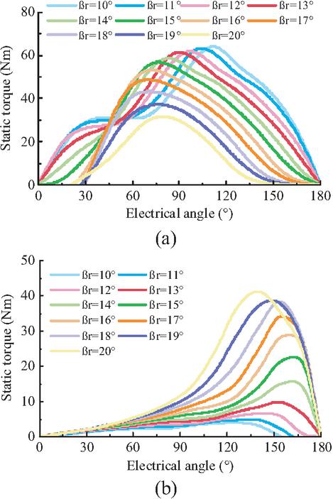
Figure 12 Static torque waveforms variation with rotor pole arc angle in the two winding polarity arrangement: (a) NSNS and (b) NSSN.
Table 3 Average torque values variation with rotor pole arc angle in two winding polarity arrangement
| Winding Polarity | NSNS | NSSN |
| 25.751 Nm | 07.053 Nm | |
| 22.396 Nm | 08.733 Nm | |
| 19.531 Nm | 10.326 Nm | |
| 16.307 Nm | 11.885 Nm | |
| 13.416 Nm | 13.296 Nm | |
| 10.424 Nm | 14.504 Nm |
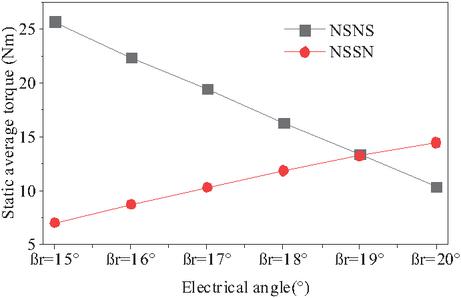
Figure 13 Static torque waveforms variation with rotor pole arc in two working modes of the motor.
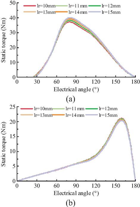
Figure 14 Static torque waveforms variation with rotor thickness in the two winding polarity arrangement: (a) NSNS and (b) NSSN.
Furthermore, the rotor radial thickness was varied from 10 mm to 15 mm. Figure 14 presents the static torque waveforms for both NSNS and NSSN winding polarity configurations as a function of rotor radial thickness. It can be observed that for both configurations, variations in rotor radial thickness produce only minor changes in the static torque waveforms. This behavior differs notably from the pronounced influence of the rotor pole arc angle previously discussed. The limited sensitivity to rotor radial thickness can be understood from the saturation perspective established above: the radial thickness primarily affects the rotor yoke cross-sectional area along the radial direction, which is not the dominant constraint on the main flux path in either configuration. In the NSSN configuration, saturation is predominantly governed by the circumferential flux concentration within the rotor teeth region, while in the NSNS configuration, the longer flux path inherently distributes the magnetic field over a sufficient core volume. Therefore, increasing the rotor radial thickness within the investigated range contributes little to relieving the flux bottlenecks that limit torque production. These results indicate that while rotor geometry does affect the static performance of the motor, the rotor pole arc angle exerts a considerably stronger influence than the rotor radial thickness. To further evaluate the practical performance differences between the two winding configurations, the dynamic electromagnetic characteristics are investigated in the following section.
4 DYNAMIC ELECTROMAGNETIC PERFORMANCE ANALYSIS
While the static torque analysis in the previous section reveals the inherent torque capability of the two winding polarity configurations, a dynamic performance assessment is essential for practical motor evaluation. Accordingly, this section investigates the dynamic torque response, torque ripple, and efficiency characteristics under both NSNS and NSSN polarity configurations across a range of operating speeds and load torques.
As a representative operating point, the dynamic torque behavior is first evaluated at a constant speed of 600 r/min with a DC bus voltage of 48 V. The drive was operated under single-pulse control (SPC) mode, with a conduction angle ranging from 0∘ to 6.43∘. The rotor pole arc coefficient was varied from 15∘ to 20∘. Figure 15 presents the dynamic electromagnetic torque waveforms under both winding configurations as a function of the rotor pole arc coefficient for this operating condition. It can be observed from Fig. 15 that as the rotor pole arc angle increases, the dynamic torque waveform under the NSNS polarity configuration exhibits a decreasing trend. In contrast, the dynamic torque under the NSSN polarity configuration is negatively correlated with the value of . To provide a clearer qualitative and quantitative evaluation of the dynamic performance of the motor under the two winding configurations, the calculated results of average torque, torque ripple, core loss, copper loss, and efficiency are summarized in Table 4.
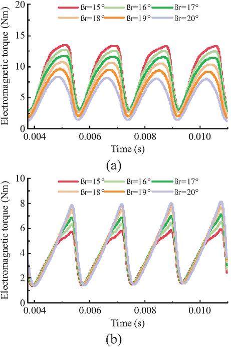
Figure 15 Transient electromagnetic torque waveforms variation with rotor thickness in the two winding polarity arrangement: (a) NSNS and (b) NSSN.
Table 4 Results of the dynamic performance of the motor at 600 r/min under two different winding polarities
| Winding Polarity | NSNS | NSSN | ||
| Rotor pole arc | ||||
| Average torque (Nm) | 9.19 | 7.23 | 4.45 | 5.12 |
| Torque ripple (%) | 119.8 | 117.2 | 114.0 | 136.3 |
| Electromagnetic power (W) | 577.1 | 454.4 | 279.3 | 325.5 |
| Power density (W/kg) | 70.38 | 55.41 | 34.06 | 39.70 |
| Copper loss (W) | 150.8 | 129.5 | 77.6 | 72.3 |
| Iron loss (W) | 55.0 | 47.2 | 28.3 | 26.4 |
| Efficiency (%) | 73.7 | 72.0 | 72.5 | 76.5 |
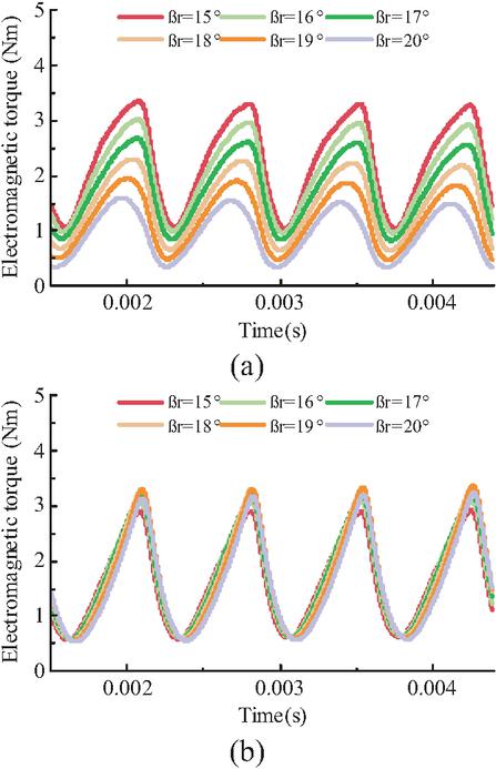
Figure 16 Transient electromagnetic torque waveforms variation with rotor thickness in the two winding polarity arrangement: (a) NSNS and (b) NSSN.
As indicated in Table 4, at a speed of 600 r/min, the average torque values of the NSNS configuration at rotor pole arc angles of 15∘ and 18∘ are 9.19 Nm and 7.23 Nm, respectively. Under the same rotor pole arc angles, the NSSN configuration yields average torque values of 4.45 Nm and 5.12 Nm, respectively. Consequently, the NSNS configuration delivers higher average torque and electromagnetic power than the NSSN configuration. Nevertheless, the NSSN configuration exhibits relatively lower copper loss and core loss. At a rotor pole arc angle of 18∘, its operating efficiency reaches 76.5%, which is superior to the 72.0% efficiency of the NSNS configuration. It is also evident that the rotor pole arc angle exerts a pronounced influence on the performance of both winding configurations. When the rotor pole arc angle is 15∘, the power density of the NSNS configuration exceeds that of the NSSN configuration by 106.6%; when the rotor pole arc angle increases to 18∘, the advantage of the NSNS configuration reduces to only 39.6%. Subsequently, the speed was increased to 1500 r/min while maintaining the same applied voltage, control mode, and phase conduction width. Figure 16 presents the dynamic torque waveforms for the two winding configurations as a function of the rotor pole arc angle . Similar to the trend observed in Fig. 15, the dynamic torque waveform of the NSNS configuration is positively correlated with the rotor pole arc angle , whereas that of the NSSN configuration exhibits a negative correlation with . The corresponding calculated results of average torque, torque ripple, losses, and efficiency at 1500 r/min are listed in Table 5.
As shown in Table 5, at a speed of 1500 r/min and a rotor pole arc angle of 15∘, the average torque values of the NSNS and NSSN configurations are 2.24 Nm and 1.65 Nm, respectively, indicating a higher torque output for the NSNS configuration. However, at a rotor pole arc angle of 18∘, the average torque of the NSNS configuration is 1.48 Nm, which falls below the 1.72 Nm produced by the NSSN configuration. This further confirms the significant influence of the rotor pole arc angle on motor performance. Additionally, the NSSN configuration exhibits relatively lower copper loss and core loss. At a rotor pole arc angle of 18∘, its operating efficiency reaches 84.1%, exceeding the 80.8% efficiency of the NSNS configuration.
Table 5 Results of the dynamic performance of the motor at 1500 r/min under two different winding polarities
| Winding Polarity | NSNS | NSSN | ||
| Rotor pole arc | ||||
| Average torque (Nm) | 2.24 | 1.48 | 1.65 | 1.72 |
| Torque ripple (%) | 108.6 | 116.4 | 152.1 | 174.9 |
| Electromagnetic power (W) | 351.61 | 231.89 | 259.13 | 270.86 |
| Power density (W/kg) | 42.88 | 28.28 | 31.60 | 33.03 |
| Copper loss (W) | 36.9 | 28.7 | 31.6 | 26.8 |
| Iron loss (W) | 33.6 | 26.2 | 28.8 | 24.4 |
| Efficiency (%) | 83.3 | 80.8 | 81.1 | 84.1 |
In summary, based on the comparison of dynamic performance under different operating conditions, it can be concluded that the two winding configurations each possess distinct advantages. Generally, the NSNS configuration can produce higher torque output, while the NSSN configuration offers lower losses and higher efficiency. Therefore, the appropriate winding configuration should be selected according to the specific application requirements. The NSNS configuration is better suited for low-speed high-torque scenarios, whereas the NSSN configuration demonstrates superior efficiency under high-speed operating conditions. It should also be emphasized that the rotor pole arc angle exerts a substantial influence on motor performance. To maximize the potential of each configuration, a relatively small rotor pole arc coefficient is recommended for the NSNS configuration, while a larger rotor pole arc coefficient is preferable for the NSSN configuration.
5 CONCLUSION
This paper investigated the influence of winding polarity distribution on modular double-stator switched reluctance motor performance. Two polarity configurations, NSNS and NSSN, were realized by varying the excitation direction of the inner and outer stator windings. Finite element analysis was employed to compare flux paths, static torque, and dynamic performance including losses and efficiency. Results show that the NSNS configuration yields higher torque output, exceeding the NSSN configuration by 106.6% at 600 r/min with 15∘ rotor pole arc angle. Conversely, the NSSN configuration exhibits lower losses and achieves an efficiency of 84.1% at 1500 r/min with 18∘ rotor pole arc angle, outperforming the NSNS configuration by 3.3 percentage points. The rotor pole arc angle exerts opposite influences on torque for the two configurations, with NSNS torque decreasing and NSSN torque increasing as the pole arc angle grows. These findings indicate that the NSNS configuration is better suited for low-speed high-torque applications, while the NSSN configuration offers advantages in high-speed high-efficiency scenarios. The appropriate winding configuration and rotor pole arc angle should therefore be selected according to specific application requirements.
ACKNOWLEDGMENT
This work is supported by the National Natural Science Foundation of China International (regional) cooperation and exchange projects NSFC-RSF (W2412064), the Basic Research Program of Jiangsu Province (BK20251662), the China Postdoctoral Science Foundation (2024M763541), the Jiangsu Provincial Market Supervision Administration Science and Technology Plan Project (KJ2025017), and the Jiangsu Funding Program for Excellent Postdoctoral Talent (2024ZB008).
REFERENCES
[1] A. Hasnain, A. Somiruwan Gamwari, R. Resalayyan, K. Farokhi Sadabadi, and A. Khaligh, “Medium- and heavy-duty vehicle electrification: Trends and technologies,” IEEE Transactions on Transportation Electrification, vol. 11, no. 1, pp. 3602–3616, Feb. 2025.
[2] P. Upadhyay and R. K, “Design of two-phase switched reluctance motor (SRM) for two-wheel electric vehicle and torque-density based comparison with three-phase SRM,” IEEE Transactions on Industry Applications, vol. 60, no. 3, pp. 3912–3919, May–June 2024.
[3] A. Kumar, B. Singh, and G. Singh, “Modified direct torque control of solar fed sensorless switched reluctance motor drive for electric vehicle with regenerative braking,” IEEE Transactions on Industry Applications, vol. 60, no. 2, pp. 3155–3164, Mar.–Apr. 2024.
[4] X. Shan, C. Gan, H. Ren, C. Zhang, H. Wang, J. Sun, S. Wang, and R. Qu, “Phase current reconstruction for Y-type converter fed switched reluctance motors drive with fault-tolerant ability,” IEEE Transactions on Power Electronics, vol. 41, no. 4, pp. 4909–4920, Apr. 2026.
[5] W. Yan, H. Chen, S. Liao, Y. Liu, and H. Cheng, “Design of a low-ripple double-modular-stator switched reluctance machine for electric vehicle applications,” IEEE Transactions on Transportation Electrification, vol. 7, no. 3, pp. 1349–1358, Sep. 2021.
[6] X. Sun, K. Diao, G. Lei, Y. Guo, and J. Zhu, “Study on segmented-rotor switched reluctance motors with different rotor pole numbers for BSG system of hybrid electric vehicles,” IEEE Transactions on Vehicular Technology, vol. 68, no. 6, pp. 5537–5547, June 2019.
[7] W. Sun, Q. Li, L. Sun, and X. Jiang, “Study on magnetic shielding for performance improvement of axial-field dual-rotor segmented switched reluctance machine,” CES Transactions on Electrical Machines and Systems, vol. 5, no. 1, pp. 50–61, Mar. 2021.
[8] G. Davarpanah, J. Faiz, H. Shirzad, and M. Lotfizadeh, “A modular hybrid excited switched reluctance motor with two groups of permanent magnets to enhance the performance of the motor,” IEEE Transactions on Energy Conversion, vol. 39, no. 3, pp. 1686–1698, Sep. 2024.
[9] R. Jayarajan, N. Fernando, and I. U. Nutkani, “A review on variable flux machine technology: Topologies, control strategies and magnetic materials,” IEEE Access, vol. 7, pp. 70141–70156, 2019.
[10] X. An, G. Liu, Q. Chen, and X. Sun, “New cost function design for robustness deadbeat model predictive control of a five-phase PMSM,” IEEE Transactions on Transportation Electrification, vol. 11, no. 6, pp. 13934–13946, Dec. 2025.
[11] B. S. Abdel-Mageed, A. M. Aljehaimi, and P. Pillay, “Analysis of design topologies for variable flux permanent magnet motors,” IEEE Transactions on Industry Applications, vol. 62, no. 1, pp. 939–955, Jan.–Feb. 2026.
[12] H. Hua, Z. Zhou, and W. Hua, “Investigation of dual-effect air-gap field regulation mechanism in variable flux memory machines,” IEEE Transactions on Industrial Electronics, vol. 71, no. 8, pp. 8571–8580, Aug. 2024.
[13] L. Sun, H. Vansompel, Z. Zhang, and P. Sergeant, “Winding configurations of a switched reluctance generator system excited by circulating current,” in 2022 International Conference on Electrical Machines (ICEM), Valencia, Spain, pp. 2067–207, 2022.
[14] X. Y. Ma, G. J. Li, G. W. Jewell, and Z. Q. Zhu, “Recent development of reluctance machines with different winding configurations, excitation methods, and machine structures,” CES Transactions on Electrical Machines and Systems, vol. 2, no. 1, pp. 82–92, Mar. 2018.
[15] S. Pal, D. Roy, M. W. Rahaman, and M. Sengupta, “Investigations on vibration studies of a 4-phase double-sided axial flux switched reluctance motor with different terminal connections,” in 2022 IEEE International Conference on Power Electronics, Drives and Energy Systems (PEDES), Jaipur, India, pp. 1–6, 2022.
[16] F. Ni, S. Niu, Z. Li, and X. Zhao, “Novel electrically excited doubly salient variable reluctance machine with high-order-harmonic winding,” IEEE Transactions on Magnetics, vol. 59, no. 11, pp. 1–6, Nov. 2023.
[17] W. Yan, J. Hu, H. Li, H. Chen, Y. Wang, and Q. Wang, “Research on high-performance control method of double-stator switched reluctance generator,” IEEE/ASME Transactions on Mechatronics, vol. 31, no. 2, pp. 1254–1264, Apr. 2026.
[18] B. Gecer, N. F. O. Serteller, and A. N. Akpolat, “Comprehensive analysis and measurements of switched reluctance motor,” Insight - Non-Destructive Testing and Condition Monitoring, vol. 68, no. 1, pp. 54–60, Jan. 2026.
[19] H. Chen, C. Liu, X. Wang, N. Korovkin, S. Liudmila, P. S. Olegovich, and B. E. Alexandrovich, “Mathematical modeling and electromagnetic force analysis of novel tubular linear rotary switched reluctance machine,” IEEE Transactions on Plasma Science, vol. 54, no. 1, pp. 270–278, Jan. 2026.
[20] S. Hussain, A. Kallaste, M. U. Naseer, H. Tiismus, M. Sarap, B. Asad, and T. Vaimann, “Design and prototyping of additively manufactured axial flux switched reluctance machine,” IEEE Transactions on Industry Applications, vol. 62, no. 2, pp. 2587–2597, Mar.–Apr. 2026.
BIOGRAPHIES

Fengyuan Yu received the Ph.D. degree from the School of Electrical Engineering, China University of Mining and Technology, Xuzhou, China, in 2023, where he was a Post-Doctoral Researcher from 2023 to 2026. Since 2026, he has been a Lecturer with the School of Electrical Engineering and Automation, Jiangsu Normal University, Xuzhou. His research interests include switched reluctance drive, special motor design, power converters, and motor control.

Hao Chen received his B.S. and Ph.D. degrees from the Department of Automatic Control, Nanjing University of Aeronautics and Astronautics, Nanjing, China, in 1991 and 1996, respectively. In 1998, he became an Associate Professor with the School of Information and Electrical Engineering, China University of Mining and Technology, Xuzhou, where he has been a Professor since 2001. From 2002 to 2003, he was a Visiting Professor at Kyungsung University, Busan, Korea. Since 2008, he has also been an Adjunct Professor at the University of Western Australia, Perth, Australia. He is the author of one book and has also authored more than 190 papers. He is the holder of 14 US Patents, 23 Australian Patents, one Danish Patent, seven Canadian Patents, three South African Patents, 10 Russian Patents, 44 Chinese Invention Patents and six Chinese Utility Model Patents. His current research interests include motor control, linear launcher, electric vehicles, electric traction, servo drives, and wind power generator control.
Chen was the recipient of both the Prize of Science and Technology of Chinese Youth and the Prize of the Fok Ying Tong Education Foundation for Youth Teachers in both 2004. He was awarded the first prize in the Science and Technology advanced of Province and Ministry once, the second prize in the Science and Technology advanced of Province and Ministry seven times, and the third prize in the Science and Technology advanced of Province and Ministry 14 times. He became the Chinese New Century Hundred-Thousand Ten-Thousand Talents Engineering National Talent in 2007 and won the Government Especial Allowance of People’s Republic of China State Department in 2006.

Haidong Yan was born in May 1982. He has a master’s degree in System Analysis and Integration from Nanjing University of Information Science & Technology, China. He is a Senior Engineer currently serving as the deputy director of Wuxi Institute of Inspection, Testing, and Certification. His research direction mainly focuses on electromagnetic metrology, new energy vehicle specialized metrology, and testing technology.

Guanjun Wang, male, born in September 1986, master’s degree in Electronic and Communication Engineering from China University of Mining and Technology, China. Senior Engineer. Currently serving as the director of Electrical and Information M&R Department of Wuxi Institute of Inspection, Testing, and Certification. His research direction mainly focuses on electromagnetic metrology, new energy vehicle specialized metrology and testing technology.

Jun Bao was born in August 1971. He is a Full Senior Engineer, currently serving as the director of Wuxi Institute of Inspection, Testing and Certification, China. His primary research areas include inspection and testing technologies for new energy vehicles, as well as metrological test technologies.
ACES JOURNAL, Vol. 41, No. 6, 577–588
DOI: 10.13052/2026.ACES.J.410608
© 2026 River Publishers