A Deep Learning and NSGA-II Based Multi-Objective Optimization Framework for SAR-Aware AMC-Backed Wearable Antenna Design
Muthukumaravel K1 and Suganthi Santhanam2
1Department of Electronics and Communication Engineering, Meenakshi Ramaswamy Engineering College, Thathanur, Ariyalur, Tamil Nadu, India
muthu.kadhir@gmail.com
2Department of Electronics and Communication Engineering, K.Ramakrishnan College of Technology, Samayapuram, Trichy, Tamil Nadu, India
suganthis.ece@krct.ac.in
Submitted On: February 22, 2026; Accepted On: June 30, 2026
ABSTRACT
This paper presents a SAR-aware machine-learning framework for optimizing an AMC-backed triple-band wearable antenna based on a two-iteration Sierpinski carpet radiator operating at 1.82, 2.42, and 5.00 GHz. A 600-sample full-wave CST dataset varies feed length, AMC-to-antenna gap, fractal scale, and AMC inter-cell gap. A multi-task DNN maps four normalized inputs to twelve outputs: gain, resonance-frequency deviation, SAR1g, and SAR10g across all bands. NSGA-II then identifies Pareto-optimal gain–SAR trade-offs, while SHAP indicates feed length and AMC gap dominate SAR. The optimized design achieves gains of 4.12/4.25/4.38 dBi and SAR of 0.082/0.075 W/kg, satisfying IEEE C95.1 and ICNIRP limits and improving over 2.6–2.9 dBi standalone gain values.
Keywords: 5G sub-6 GHz, artificial magnetic conductor (AMC), deep learning, fractal geometry, machine learning, NSGA-II, SAR-aware design, wearable antenna..
1 INTRODUCTION
Wearable and mobile communication systems require compact antennas that can operate near the human body without degrading radiation performance or exceeding Specific Absorption Rate (SAR) limits. In body-centric operation, biological tissues behave as lossy dielectric media, causing electromagnetic absorption, bandwidth variation, gain reduction, and efficiency loss. This issue is critical for sub-6 GHz 5G and healthcare devices, where SAR reduction must be achieved without sacrificing antenna performance.
Fractal geometries, including the Sierpinski carpet, are widely used for compact multiband antennas because they increase the effective current path within a small radiator area. However, fractal radiators alone can produce localized near-field concentration around the feed and fractal edges. When placed close to lossy tissue, this effect may increase backward radiation, reduce radiation efficiency, and raise SAR. Hence, compact multiband operation must be supported by a structure that controls body-directed radiation.
Artificial magnetic conductors (AMCs) mitigate the performance degradation caused by the close proximity of wearable antennas to the human body by providing an approximately in-phase reflection response within their operating band. When positioned behind the radiating element, AMC surfaces can reduce body-directed radiation, enhance forward gain, and support lower specific absorption rate (SAR). These benefits have been demonstrated using AMC-integrated cavity-backed substrate-integrated waveguide antennas, dual-band low-SAR MIMO configurations, 2.4-GHz wearable antennas, fabric-based body-centric antennas, conformal dual-band structures, textile antennas, and compact biomedical wearable platforms [1, 2, 3, 4, 5, 6, 7, 8]. Recent data-driven antenna studies have also progressed from comprehensive ML and deep-learning reviews to hybrid electromagnetic modelling of UWB MIMO antennas, convolutional-neural-network-based near-field prediction, incremental variable-fidelity multiobjective optimization, and ML-assisted synthesis of dielectric-filled slotted-waveguide antennas with prescribed sidelobe levels [9, 10, 11, 12, 13]. These developments demonstrate the increasing importance of computationally efficient and performance-aware optimization in complex antenna systems.
Fractal geometries have been employed to obtain compact and low-profile wearable antennas, including on-body WBAN radiators, flexible dual-band tree-fractal structures, and hybrid fractal antennas optimized using artificial neural networks and firefly algorithms. Wideband AMC loading has additionally been used to enhance the gain and off-body communication performance of low-profile monopole antennas [14, 15, 16, 17]. A low-profile all-textile UWB antenna incorporating an AMC was subsequently developed for WBAN applications [18]. Curvature-adaptive triple-band metamaterial and uniplanar compact electromagnetic-bandgap loading has been investigated for wearable wireless and medical body-area networks [19]. A breathable triple-band EBG-loaded fractal antenna has also been proposed for WBAN operation [20], while a metamaterial-inspired dual-band antenna has been examined for body-area communication applications [21]. Although these studies demonstrate the benefits of fractal, AMC, EBG, and metamaterial loading, the simultaneous optimization of gain, radiation efficiency, resonance stability, and SAR within a unified and interpretable design framework remains insufficiently explored.
Machine learning has increasingly been applied to antenna modelling and optimization because it can represent nonlinear relationships between geometrical parameters and electromagnetic responses. Data augmentation has been incorporated into ML-assisted antenna optimization to improve prediction using limited training samples [22]. Data-driven models have also been developed to predict the resonant frequency and directivity of UMTS/LTE quasi-Yagi antennas [23], while established ML techniques have been employed to optimize double T-shaped monopole antennas [24]. An efficient modified K-nearest-neighbour method has been introduced for antenna optimization and design [25]. Neural-network-assisted optimization has further been investigated for electromagnetic applications [26], and a deep-reinforcement-learning framework has been developed for automated antenna optimization [27]. A compact triband antenna employing an AMC reflector has also demonstrated the suitability of AMC-backed configurations for WBAN communication [28]. Motivated by these developments, the present study combines AMC loading and fractal geometry with a deep-neural-network surrogate model, NSGA-II-based multiobjective optimization, and SHapley Additive exPlanations interpretation to achieve simultaneous multiband gain enhancement and SAR reduction.
1.1 Motivation and contribution
This work presents a SAR-aware ML-assisted optimization framework for a compact AMC-backed triple-band wearable antenna operating at 1.82, 2.42, and 5.00 GHz. The radiator uses a two-iteration Sierpinski carpet fractal geometry. A 600-sample CST dataset is generated by varying feed length, AMC-to-antenna gap, fractal scale factor, and AMC inter-cell gap to model gain, resonance stability, SAR1g, and SAR10g. A DNN surrogate predicts realized gain, resonance-frequency deviation, SAR1g, and SAR10g across the three bands and is coupled with NSGA-II for gain maximization and SAR minimization. SHAP analysis identifies the dominant design variables controlling gain and SAR. Compared with the authors’ previous work [28], which reported the baseline fractal AMC-backed antenna, this study adds SAR-aware DNN modeling, NSGA-II multi-objective optimization, SHAP-based interpretation, and gain–SAR trade-off analysis. The optimized design improves realized gain from 2.6–2.9 dBi to 4.12–4.38 dBi, while reducing SAR to 0.082 W/kg for 1 g tissue and 0.075 W/kg for 10 g tissue, satisfying IEEE C95.1 and ICNIRP limits.
2 BASELINE ANTENNA OVERVIEW
The baseline antenna geometry is adopted from the authors’ earlier work [28], where a compact triple-band fractal antenna with AMC backing was conventionally characterized. In the present work, the same geometry is used only as the starting platform for SAR-aware ML optimization. The DNN training, NSGA-II optimization, SHAP interpretation, gain–SAR trade-off analysis, and SAR-constrained design selection are newly developed in this study. The reference antenna consists of a two-iteration hybrid Sierpinski–Koch fractal radiator on a flexible FR4 substrate with thickness 1.82 mm, relative permittivity , and loss tangent 0.02. The antenna has a compact footprint of . A coplanar waveguide (CPW) feed excites the planar radiator, while the etched fractal slots increase the effective electrical length and support multiband resonance without increasing the antenna size.
Figure 1 shows the standalone fractal antenna, and Fig. 2 presents its simulated reflection coefficient. The antenna resonates at 1.82 GHz, 2.42 GHz, and 5.0 GHz, covering ISM, WLAN, and sub-6 GHz 5G bands. The corresponding realized gains are 2.6dBi, 2.72dBi, and 2.9dBi. However, without reflective backing, backward radiation and surface-wave propagation reduce forward gain and radiation efficiency. SAR simulations also indicate increased tissue absorption during on-body operation. These limitations motivate AMC integration and ML-assisted gain–SAR optimization in the following sections.
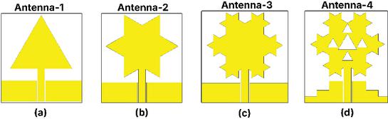
Figure 1 Geometry of the standalone fractal antenna.
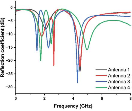
Figure 2 Simulated reflection coefficient () for the baseline antenna.
3 AMC DESIGN AND CHARACTERIZATION FOR SAR REDUCTION AND GAIN ENHANCEMENT
The AMC backing is introduced to reduce SAR and improve forward gain in near-body operation by reflecting backward-directed fields in phase. This reduces body-directed radiation, which is critical for wearable antennas placed close to lossy tissue.
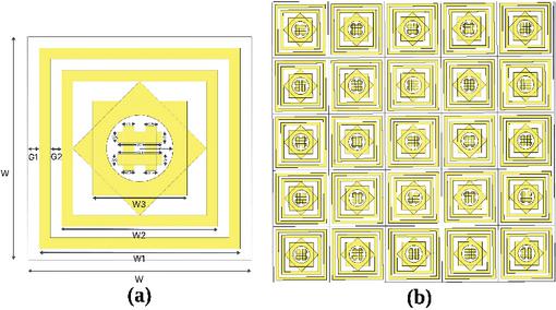
Figure 3 (a) AMC unit cell geometry; (b) AMC array layout.
3.1 AMC unit cell design
The AMC unit cell in Fig. 3 uses three concentric square-ring resonators tuned to 1.82, 2.42, and 5.00 GHz. A central grid patch provides capacitive coupling for miniaturization and high surface impedance. The unit cell is designed on a 1.82 mm FR4 substrate with , , a 35 m copper layer, and a continuous ground plane. The dimensions are listed in Table 1.
The AMC unit-cell outer dimension is , denoted by . The value is not the unit-cell periodicity; it represents the AMC inter-cell gap between adjacent cells in the array. Including this gap, the effective array pitch is approximately . This distinction avoids confusion among unit-cell size, array pitch, and inter-cell spacing.
Table 1 Geometrical dimensions of the AMC unit cell
| Parameter | Value (mm) |
| 9.00 | |
| 7.00 | |
| 4.24 | |
| 3.00 | |
| 0.50 | |
| 0.50 | |
| 0.50 | |
| 3.00 |
3.2 Operating principle, reflection phase, and bandwidth
The AMC operates as an equivalent parallel LC network, where the square rings provide inductance and the inter-ring gaps provide capacitance. Its resonance frequency is approximated by
| (1) |
Unlike a PEC surface, which introduces a phase shift, the AMC provides near-zero reflection phase at resonance and prevents destructive interference with the radiator.
Full-wave simulations under normal plane-wave incidence with periodic boundary conditions confirm tri-band AMC behavior. Figure 4 shows zero-phase crossings at 1.8 GHz, 2.42 GHz, and 5 GHz. The 2.42 GHz ISM band provides an usable bandwidth of approximately 327 MHz, supporting stable wearable biomedical and communication operation.
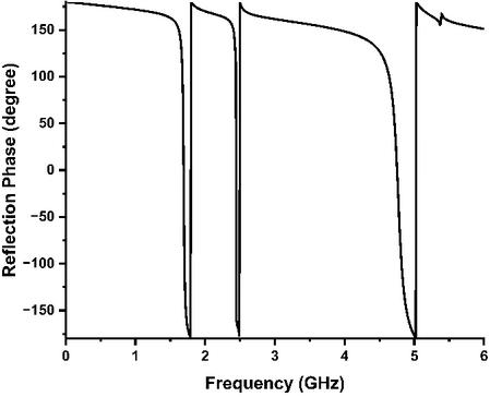
Figure 4 Reflection phase response of AMC unit cell.
4 INTEGRATION OF AMC WITH ANTENNA
The triple-band fractal antenna was integrated with the AMC array and first evaluated under free-space conditions to isolate the effect of AMC backing before human-body loading. At the operating bands, the AMC reflects backward-directed fields in phase, suppresses body-facing radiation, improves forward gain, and supports SAR reduction.
4.1 Antenna fabrication and AMC array configuration
The AMC backing was realized as a array of tri-band AMC unit cells resonating at 1.82, 2.42, and 5.00 GHz. The inter-cell spacing is denoted as , which is not the unit-cell periodicity. Each unit cell has an outer lateral dimension of , giving an effective array pitch of approximately when is included.
The AMC layer was fabricated on a 1.6 mm FR4 substrate with and loss tangent 0.02. The fractal antenna was fabricated on an identical FR4 substrate and excited through a CPW feed. An optimized AMC-to-antenna air gap of was maintained using low-loss dielectric spacers. This vertical separation was selected from the NSGA-II-optimized design to balance forward-gain enhancement, SAR reduction, and compact profile.
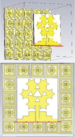
Figure 5 3D model of the AMC-integrated antenna, highlighting the optimized AMC-to-antenna air gap .
Figure 5 shows the 3D AMC-integrated antenna and highlights the optimized air gap. Figure 6 presents the fabricated prototype and measurement arrangement, where the radiator and AMC layer are assembled with .
The reflection coefficient was measured using a vector network analyzer after standard SOLT calibration at the SMA connector reference plane. The standalone and AMC-backed antennas were measured under identical calibration conditions. For the AMC-backed case, the radiator and AMC layer were kept parallel, and was maintained during measurement. Gain and radiation patterns were measured using a calibrated reference antenna in a standard far-field setup. The antenna under test was placed on a low-reflection support, and patterns were recorded at 1.82, 2.42, and 5.00 GHz. Minor differences between simulated and measured results are attributed to fabrication tolerance, FR4-property variation, SMA soldering, conductor roughness, cable and connector losses, air-gap misalignment, and residual environmental reflections. Nevertheless, the measured trends confirm gain enhancement, improved forward radiation, and higher radiation efficiency with AMC backing.
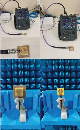
Figure 6 Fabricated AMC-backed triple-band fractal antenna prototype and measurement arrangement, showing the assembled radiator–AMC configuration with the optimized AMC-to-antenna air gap .
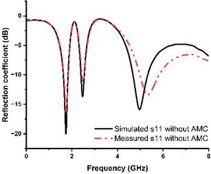
Figure 7 Simulated and measured of the standalone antenna at 1.82, 2.42, and 5.00 GHz.
4.2 Reflection coefficient comparison
The measured reflection coefficient of the standalone and AMC-backed antennas is shown in Figs. 7 and 8. The standalone antenna exhibits resonance dips of , , and at 1.82, 2.42, and 5.00 GHz, confirming triple-band operation. With AMC backing, the dips improve to , , and , with a broader bandwidth of about 820 MHz near 2.42 GHz. The improvement is due to AMC in-phase reflection, which stabilizes impedance matching and suppresses backward radiation. Minor simulation–measurement shifts arise from fabrication tolerances.
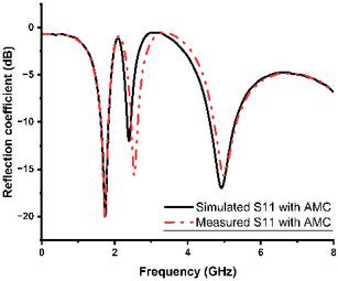
Figure 8 Simulated and measured of the AMC-backed antenna at 1.82, 2.42, and 5.00 GHz.
4.3 Gain analysis
Figure 9 compares the realized gain of the standalone and AMC-backed antennas. At 1.82, 2.42, and 5.00 GHz, the gain increases from 2.60, 2.72, and 2.90 dBi to 4.12, 4.25, and 4.38 dBi, respectively. This enhancement results from improved impedance matching, higher radiation efficiency, reduced body-directed radiation, and constructive AMC reflection toward the forward hemisphere.
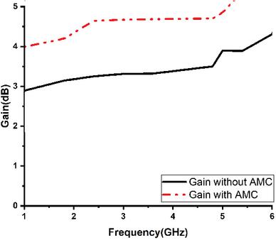
Figure 9 Gain comparison of the standalone and AMC-backed antenna configurations over the operating frequency range.
4.4 Radiation pattern and efficiency evaluation
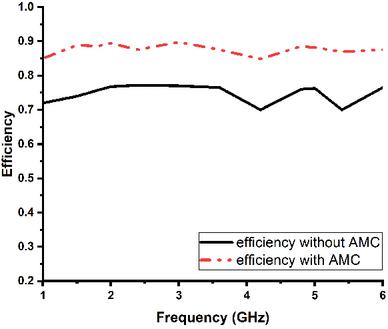
Figure 10 Simulated and measured total radiation efficiency of the AMC-backed antenna at 1.82, 2.42, and 5.00 GHz.
Figure 10 shows the total radiation efficiency. The standalone antenna achieves 72–78%, whereas the AMC-backed design exceeds 85% across all operating bands. This confirms reduced substrate-mode loss and surface-wave propagation after AMC integration. The gain improvement is therefore due to both higher accepted-power radiation and improved forward directivity.
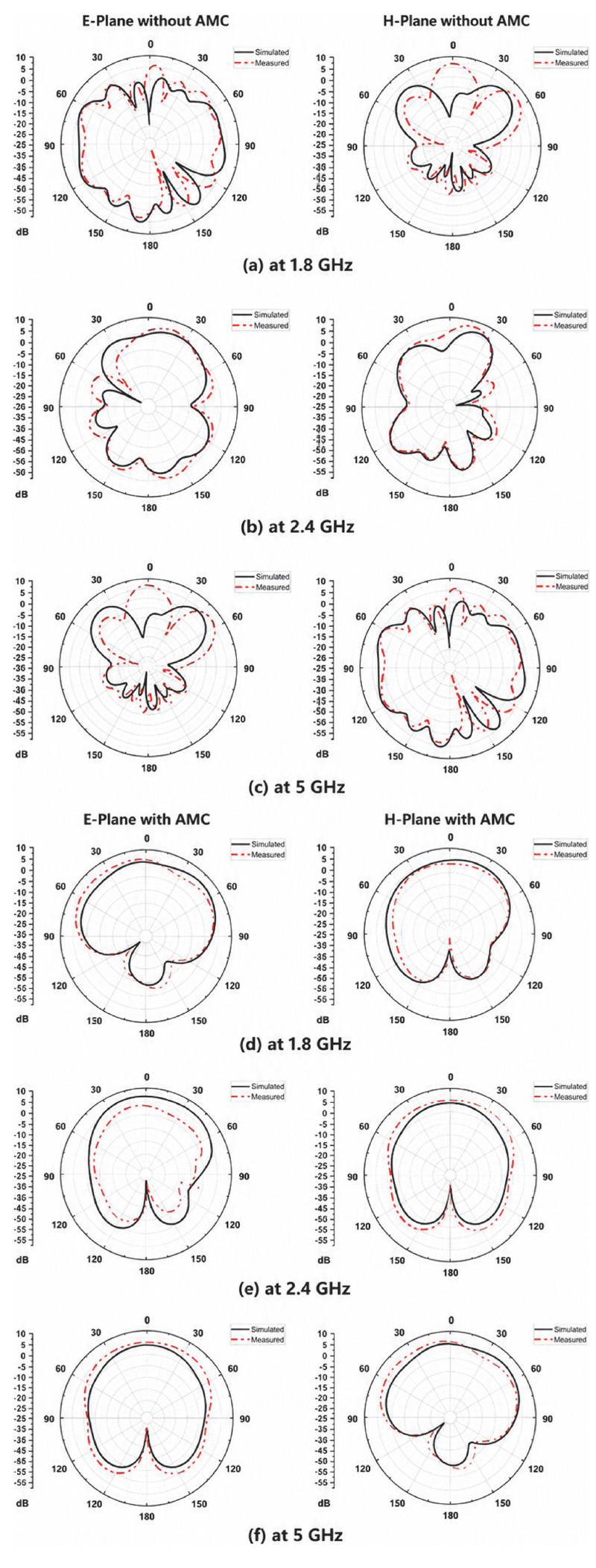
Figure 11 Simulated and measured radiation patterns at (a) 1.82 GHz, (b) 2.42 GHz, and (c) 5 GHz without AMC, and (d) 1.82 GHz, (e) 2.42 GHz, and (f) 5 GHz with AMC.
The E-plane and H-plane radiation patterns in Figs. 11 (a)–(f) show stronger forward radiation and suppressed back lobes after AMC integration. This behavior supports stable wearable links and reduces user-directed electromagnetic exposure.
4.5 Wearable applicability and practical stability considerations
For wearable operation, bending, body proximity, wearing position, and deformation can affect impedance matching, radiation pattern, and SAR distribution. The AMC backing therefore acts not only as a gain-enhancement layer but also as an electromagnetic isolation layer between the radiator and lossy tissue. Bending modifies the effective current path of the fractal radiator and the spacing between the radiator and AMC surface, which may cause small resonance shifts and impedance variation. The AMC-backed structure is expected to be more stable than the standalone radiator because it suppresses backward radiation and reduces near-field coupling into the body. The optimized AMC-to-antenna air gap further maintains controlled radiator–AMC coupling.
Antenna response may also vary with placement on the arm, chest, shoulder, or wrist due to differences in curvature, tissue thickness, and dielectric loading. Strongly curved regions can introduce larger detuning than flatter regions, while closer body contact may slightly reduce radiation efficiency. The AMC reduces these effects by redirecting radiation away from the body-facing side and limiting field penetration into tissue. From the SAR perspective, the AMC suppresses backward-directed fields and reduces tissue absorption. Thus, the optimized AMC-backed antenna is expected to maintain lower SAR than the standalone antenna under close-body operation, as discussed in the SAR analysis section. Although the present work verifies SAR reduction, gain enhancement, and stable radiation behavior through simulation and measurement, complete garment-level validation is beyond its scope. Future work will include repeated bending cycles, different bending radii, and multi-position body measurements. Therefore, the claim is limited to SAR-aware, AMC-backed wearable-oriented operation.
5 SAR-AWARE MACHINE LEARNING-BASED OPTIMIZATION FRAMEWORK
5.1 Motivation and problem formulation
Wearable and body-centric antennas require compact, efficient, and SAR-compliant operation. Conventional optimization mainly targets gain, impedance bandwidth, and radiation efficiency, but neglecting SAR in close-body use may violate international safety limits. Therefore, this work integrates SAR directly into an ML-assisted optimization loop for the AMC-backed triple-band fractal antenna operating at 1.82, 2.42, and 5.00 GHz.
The framework combines CST full-wave simulation, supervised learning, and evolutionary optimization. A dataset of 600 antenna geometries was generated by varying four design variables: feed length , which controls input impedance, CPW-fed current distribution, and local electric-field concentration; AMC-to-antenna air gap , which defines the vertical separation between the radiator and AMC surface and affects coupling, in-phase reflection, forward gain, and SAR; fractal scale factor , which tunes effective current-path length and resonance positions; and AMC inter-cell gap , which controls coupling between adjacent AMC cells in the array, reflection-phase stability, field confinement, and surface-wave suppression.
The same variables are used for dataset generation, DNN surrogate training, NSGA-II optimization, and SHAP analysis. Here, denotes the AMC inter-cell gap, not the AMC unit-cell periodicity; the optimized value of 0.5 mm represents the spacing between adjacent AMC cells. Similarly, denotes the vertical AMC-to-antenna air gap.
For each geometry, realized gain, radiation efficiency, resonance-frequency deviation, SAR1g, and SAR10g were extracted at each operating band. Figure 12 summarizes the complete pipeline: CST-based dataset generation, DNN surrogate modeling, NSGA-II-based multi-objective gain–SAR optimization, and SHAP-based interpretation of parameter influence.
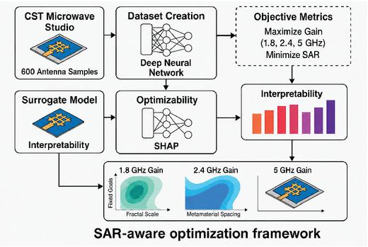
Figure 12 SAR-aware optimization framework integrating CST-driven dataset generation, DNN-based surrogate modeling, SHAP interpretability, and NSGA-II optimization for gain–SAR trade-offs across 1.82, 2.42, and 5.00 GHz.
5.2 Definition of optimization variables and sampling strategy
The four geometrical variables used for dataset generation, DNN training, and NSGA-II optimization are defined in Table 2: feed length , AMC-to-antenna air gap , fractal scale factor , and AMC inter-cell gap . These variables govern impedance matching, resonance tuning, near-field coupling, backward-radiation suppression, realized gain, and SAR distribution. Here, denotes the spacing between adjacent AMC cells in the array, not the AMC unit-cell periodicity. The vertical separation between the radiator and AMC is denoted as .
Table 2 Optimization variables for DNN–NSGA-II training
| Var. | Sym. | Physical Role | Range | Opt. |
| Feed length | Controls CPW current path, impedance matching, and feed-region electric-field concentration | 8.5–10.5 mm | 9.6 mm | |
| AMC air gap | Radiator–AMC spacing; controls in-phase reflection, coupling, forward gain, and SAR | 2.5–4.5 mm | 3 mm | |
| Fractal scale | Controls effective radiator length and tunes 1.82, 2.42, and 5.00 GHz resonances | 1.6–2.4 | 2.0 | |
| AMC cell gap | Gap between adjacent AMC cells in the array; controls coupling and reflection-phase stability | 0.3–0.7 mm | 0.5 mm | |
| All variables were sampled using Latin hypercube sampling. Here, is the AMC inter-cell gap, not the AMC unit-cell periodicity. | ||||
A total of 600 full-wave CST samples were generated within the bounds in Table 2 using Latin hypercube sampling. The ranges include the nominal geometry and fabrication-tolerant variations. For each sample, resonant frequency, realized gain, radiation efficiency, resonance-frequency deviation, SAR1g, and SAR10g were extracted at 1.82, 2.42, and 5.00 GHz for surrogate modeling and multi-objective optimization.
5.3 Dataset generation
Each CST sample was arranged as an input–output pair. The input vector is
| (2) |
where the variables follow the definitions in Table 2. For each operating band, the target outputs were realized gain, resonance-frequency deviation, SAR1g, and SAR10g; hence, each sample had a twelve-component output vector across 1.82, 2.42, and 5.00 GHz. Radiation efficiency was also retained for performance evaluation.
The dataset was balanced across the selected design space to reduce bias and overfitting. SAR extraction used the same phantom model, antenna-to-phantom distance, input-power normalization, tissue properties, and mesh settings for all samples. This ensured consistent SAR labels for DNN training and NSGA-II optimization.
1. Deep neural network (DNN) architecture
A fully connected multi-task DNN was used as a surrogate model to predict gain, resonance stability, and SAR from antenna geometry at 1.82, 2.42, and 5.00 GHz. A single model was trained for all three bands, as shown in Fig. 13. The normalized input vector is defined as
| (3) |
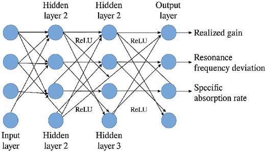
Figure 13 DNN architecture with four geometrical input variables and twelve linear output nodes for predicting realized gain, resonance-frequency deviation, SAR1g, and SAR10g at 1.82, 2.42, and 5.00 GHz.
where , , , and denote feed length, AMC-to-antenna air gap, fractal scale factor, and AMC inter-cell gap, respectively.
To avoid a long single-column equation, the output vector is defined frequency-wise as
| (4) |
where
| (5) |
Here, , , , and represent realized gain, resonance-frequency deviation, 1 g SAR, and 10 g SAR at frequency , respectively, where GHz. The resonance-frequency deviation is calculated as
| (6) |
where is obtained from the simulated reflection coefficient and is the target frequency.
The DNN consists of four input neurons, three fully connected hidden layers with 128, 64, and 32 ReLU neurons, and twelve linear output neurons. Training used the Adam optimizer with an initial learning rate of , batch size of 32, maximum 500 epochs, early stopping with 30-epoch patience, and an 80:20 training–validation split. All variables were normalized during training and converted back to physical units after prediction.
A weighted multi-task MAE loss was used to prioritize SAR prediction. For compact notation, the error terms at each frequency are defined as
| (7) |
The total weighted loss is then written as
| (8) | ||
where GHz. The loss weights are
| (9) | ||
The higher SAR weights emphasize biological safety while preserving gain and resonance-deviation accuracy.
Model accuracy was evaluated using RMSE and :
| (10) |
| (11) |
The trained DNN achieved for frequency-dependent gain and SAR prediction. During optimization, SAR1g and SAR10g were predicted at each band, and the worst-case SAR across the three bands was used for safety-constrained design selection.
2. NSGA-II multi-Objective genetic algorithm
The trained DNN was coupled with NSGA-II to search for antenna geometries that balance gain, resonance stability, and SAR at 1.82, 2.42, and 5.00 GHz. The design variables were , , , and , with the same bounds used during CST dataset generation. For each candidate geometry, the DNN predicted realized gain, resonance-frequency deviation, SAR1g, and SAR10g at all bands.
The optimization maximized realized gain and minimized resonance-frequency deviation, SAR1g, and SAR10g. The worst-case SAR across the three bands was used for constraint handling. Table 3 lists the NSGA-II settings, including binary tournament selection, simulated binary crossover, polynomial mutation, and penalty-based feasibility ranking.
Table 3 NSGA-II settings for SAR-aware optimization
| Parameter | Value/Method |
| Design variables | 4 |
| Population size | 100 |
| Generations | 50 |
| Parent selection | Binary tournament |
| Crossover | Simulated binary crossover; probability = 0.90; distribution index = 20 |
| Mutation | Polynomial mutation; probability = 0.25; distribution index = 20 |
| Constraint handling | Penalty-based feasibility ranking |
| Stopping criterion | Maximum generations or negligible Pareto-front spread improvement |
Candidate solutions exceeding SAR or SAR were penalized. Designs with large resonance deviation were also ranked lower to avoid low-SAR but mismatched solutions. The Pareto plots in 18, and 19 are two-dimensional projections of the higher-dimensional solution space. Final selection used the full multi-frequency DNN output, including gain, resonance deviation, SAR1g, and SAR10g at 1.82, 2.42, and 5.00 GHz. The selected feasible non-dominated design achieved realized gains of 4.12, 4.25, and 4.38 dBi at 1.82, 2.42, and 5.00 GHz, respectively, while maintaining SAR and SAR.
5.4 SHAP and interpretability analysis
SHAP were used to interpret the DNN predictions and relate the learned trends to antenna physics. This step is important because the proposed framework targets high realized gain while maintaining SAR below the imposed limits of SAR W/kg and SAR W/kg.
Figure 14 shows the SHAP feature importance for SAR1g and SAR10g. Feed length and AMC-to-antenna air gap have the strongest influence on SAR, followed by AMC inter-cell gap , while the fractal scale factor has the lowest SAR contribution. This trend is physically consistent. The feed length modifies the CPW-fed current distribution and local electric-field hotspots, whereas controls near-field coupling, backward-radiation suppression, and body-facing field penetration. The inter-cell gap affects AMC coupling and reflection-phase stability, while mainly governs resonance tuning and gain. Thus, SHAP confirms that the gain–SAR optimization is physically meaningful and not only data-driven.
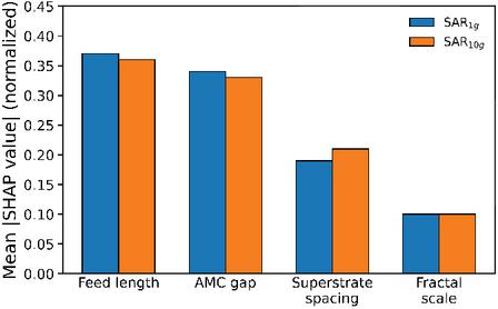
Figure 14 SHAP feature importance for SAR1g and SAR10g highlighting the dominant influence of feed length and AMC-to-antenna air gap .
5.5 Optimization results and analysis
1. Model performance comparison
The proposed SAR-aware framework was evaluated by comparing a standalone DNN predictor with the hybrid NSGA-II + DNN approach. The comparison considered realized gain at 1.82, 2.42, and 5 GHz, SAR1g, SAR10g, and total radiation efficiency, as summarized in Table 4.
Table 4 Comparison of ML optimization strategies
| Model | Gain† | SAR1g | SAR10g/Eff. |
| (dBi) | (W/kg) | (W/kg/%) | |
| DNN-only | 4.05/4.18/4.28 | 0.088 | 0.081 / 88.2 |
| NSGA-II+DNN | 4.12/4.25/4.38 | 0.082 | 0.075 / 87.6 |
| †Gain values are reported at 1.82/2.42/5.00 GHz. | |||
The DNN-only model gives competitive gain values of 4.05 / 4.18 / 4.28 dBi, but its SAR values remain higher at 0.088 W/kg for SAR1g and 0.081 W/kg for SAR10g. The NSGA-II + DNN approach improves the gain–SAR balance, achieving 4.12 / 4.25 / 4.38 dBi at 1.82 / 2.42 / 5 GHz while reducing SAR1g to 0.082 W/kg and SAR10g to 0.075 W/kg. Both methods maintain efficiency above 87%, indicating that SAR reduction is not obtained through excessive radiation loss.
Figure 15 further shows that the NSGA-II + DNN solutions cluster in a lower-SAR region while retaining higher gain. This confirms the benefit of including SAR as an explicit optimization objective for wearable antenna design.
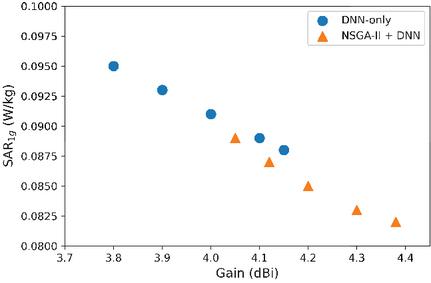
Figure 15 Comparison of DNN-only and NSGA-II-augmented optimization results showing gain–SAR1g clustering behaviour.
2. NSGA-II convergence behavior
The convergence of NSGA-II was evaluated over 50 generations to verify stable gain–SAR optimization. Figure 16 shows the SAR1g and gain evolution. During early generations, SAR fluctuates due to broad design-space exploration. After nearly 30 generations, the search converges to SAR1g near 0.082 W/kg, while gain approaches the optimized upper range of approximately 4.38 dBi. This confirms that NSGA-II can reduce SAR while maintaining high realized gain under the imposed safety constraints.
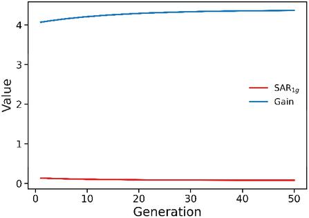
Figure 16 NSGA-II convergence behavior showing the evolution of SAR1g and gain over 50 generations.
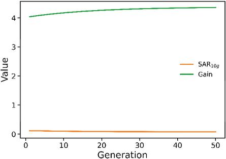
Figure 17 NSGA-II convergence trend for SAR10g and gain across 50 generations.
Figure 17 shows a similar trend for SAR10g. The convergence is more gradual because 10 g averaging smooths local field variations. The final population approaches SAR10g values close to 0.075 W/kg while retaining a stable high-gain response. Thus, the convergence results confirm that the optimized designs satisfy both electromagnetic and biological safety requirements at 1.82, 2.42, and 5 GHz.
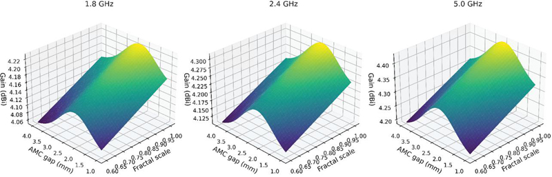
Figure 20 Gain surface plots as functions of fractal scale factor and AMC-to-antenna air gap at (a) 1.82 GHz, (b) 2.42 GHz, and (c) 5.00 GHz.
3. Pareto fronts and trade-Off plots
Pareto fronts were analyzed to evaluate the trade-off between realized gain and SAR across 1.82, 2.42, and 5 GHz. Figure 18 shows the SAR1g–gain Pareto front. Across the three bands, higher-gain solutions show a moderate SAR increase; however, SAR1g remains confined to approximately 0.076–0.086 W/kg, while realized gain reaches 4.38 dBi. This indicates that the SAR-aware constraints limit tissue exposure without preventing high-gain operation.
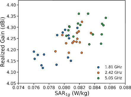
Figure 18 Pareto front for SAR1g versus realized gain across 1.82, 2.42, and 5 GHz.
Figure 19 presents the corresponding SAR10g–gain Pareto front. Due to volumetric averaging, SAR10g remains lower, within approximately 0.069–0.079 W/kg. A slight SAR10g increase occurs at higher gain levels, but all values remain below the conservative safety threshold. These Pareto fronts support selection of antenna geometries that balance gain enhancement and SAR compliance for wearable operation.
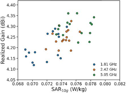
Figure 19 Pareto front for SAR10g versus realized gain across 1.82, 2.42, and 5 GHz.
4. Surface and contour analysis
Surface plots from the trained DNN surrogate were used to examine the effect of coupled design variables on gain and SAR at 1.82, 2.42, and 5.00 GHz. Here, denotes the vertical AMC-to-antenna air gap, while denotes the AMC inter-cell gap.
Figure 20 shows gain surfaces as functions of fractal scale factor and . At 5.00 GHz, gain is strongly affected by , indicating the role of current-path shaping at the upper band. At 1.82 and 2.42 GHz, gain depends on both and , showing the combined effect of fractal tuning, field confinement, and AMC in-phase reflection. In all cases, gain remains below 4.38 dBi, consistent with the NSGA-II results.
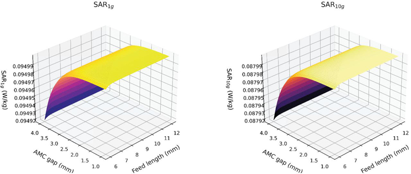
Figure 21 Surface plots of SAR1g and SAR10g as functions of feed length and AMC-to-antenna air gap .
Figure 21 maps SAR1g and SAR10g as functions of feed length and . Shorter feed lengths and smaller air gaps increase SAR due to stronger near-field coupling and localized current concentration. Moderate values with optimized form low-SAR regions, where SAR1g remains below approximately 0.086 W/kg and SAR10g remains below 0.079 W/kg without reducing gain. These maps provide direct design guidance for selecting safe high-gain geometries.
5.6 Optimized design parameters
The final NSGA-II + DNN design was selected to balance gain, resonance stability, and SAR compliance. It achieves a maximum realized gain of approximately 4.38 dBi, with SAR W/kg and SAR W/kg. These values are below IEEE C95.1 and ICNIRP exposure limits. The optimized geometry is listed in Table 5, with parameter roles supported by SHAP analysis and DNN surface responses.
Table 5 Optimized SAR-constrained geometry
| Parameter | Opt. | Design Role |
| Fractal scale | 2.0 | Sets current path and triple-band resonance; dominant gain tuning at 5.00 GHz |
| Feed length | 9.6 mm | Controls CPW current, matching, and feed-region SAR hotspots |
| AMC cell gap | 0.5 mm | Gap between AMC cells; affects coupling, phase stability, surface-wave suppression, and isolation |
| AMC air gap | 3 mm | Radiator–AMC spacing; controls in-phase reflection, gain–SAR trade-off, and radiation efficiency |
The selected values were obtained through the closed-loop CST–DNN–NSGA-II process, not through isolated tuning. The final antenna supports SAR-compliant operation at 1.82, 2.42, and 5 GHz for LTE, ISM, and sub-6 GHz 5G bands. Table 6 summarizes the main components of the SAR-aware optimization framework.
Table 6 Summary of the SAR-aware ML framework
| Component | Compact description |
| Objective | Maximize gain at 1.82, 2.42, and 5.00 GHz; minimize , SAR1g, and SAR10g |
| Variables | , , , ; : radiator–AMC gap; : AMC inter-cell gap, not periodicity |
| Dataset | 600 CST full-wave samples generated from the four-variable design space |
| DNN surrogate | Four inputs; hidden layers of 128/64/32 neurons; twelve outputs; ReLU hidden activation; linear output; SAR-weighted MAE loss |
| Outputs | Gain, , SAR1g, and SAR10g at 1.82, 2.42, and 5.00 GHz |
| Optimizer | NSGA-II: population 100, 50 generations, binary tournament, SBX crossover, polynomial mutation, SAR-penalty ranking |
| Interpretability | SHAP-based parameter ranking and physical interpretation |
| Validation | Pareto fronts, convergence plots, surface maps, and final CST verification |
| Best result | Gain up to 4.38 dBi; SAR W/kg; SAR W/kg |
Overall, the framework embeds SAR constraints into ML-based antenna optimization and supports physically interpretable design selection using SHAP and surface mapping. It maintains high gain while satisfying SAR limits across 1.82, 2.42, and 5 GHz.
6 SAR ANALYSIS AND RESULTS
The SAR performance of the proposed antenna was evaluated to verify the SAR-aware ML optimization framework discussed in the previous section. Unlike conventional AMC-backed designs that reduce SAR mainly through shielding, this work includes SAR as a constrained objective in the DNN–NSGA-II optimization loop. Thus, the reported SAR values result from simultaneous gain maximization and localized absorption minimization. Table 7 compares the standalone antenna and the optimized AMC-backed configuration.
Table 7 Standalone and optimized AMC-backed antenna performance
| Metric | Standalone | AMC opt. |
| Gain @ 1.82 GHz | 2.60 dBi | 4.12 dBi |
| Gain @ 2.42 GHz | 2.72 dBi | 4.25 dBi |
| Gain @ 5.00 GHz | 2.90 dBi | 4.38 dBi |
| Efficiency | 72–78% | |
| Back radiation | High | Suppressed |
| SAR1g | 0.71 W/kg | 0.082 W/kg |
| SAR10g | 0.21 W/kg | 0.075 W/kg |
6.1 SAR simulation setup and evaluation protocol
SAR was evaluated in CST Microwave Studio using the same finite-integration full-wave setup for both standalone and optimized AMC-backed antennas. The antenna was placed parallel to a planar multilayer human-body phantom consisting of skin, fat, and muscle. The phantom size was , with 2 mm skin, 5 mm fat, and the remaining depth modeled as muscle. The lower antenna surface was kept 5 mm above the top skin layer for both configurations. For the AMC-backed case, the AMC layer was placed between the radiator and phantom, with the optimized AMC-to-antenna air gap .
SAR values were normalized to 1 W accepted input power. Both SAR1g and SAR10g were extracted at 1.82, 2.42, and 5.00 GHz using identical tissue properties, mesh settings, input normalization, and averaging methods. SAR1g was compared with IEEE C95.1, while SAR10g was compared with ICNIRP guidelines. The simulation conditions and tissue dielectric properties are summarized in Tables 8 and 9, respectively. These same settings were also used for the CST dataset applied in DNN training and NSGA-II optimization.
Table 8 SAR simulation setup
| Parameter | Setting |
| Tool | CST Microwave Studio full-wave solver |
| Phantom | Planar skin–fat–muscle model |
| Size | |
| Layer thickness | Skin: 2 mm; fat: 5 mm; muscle: remaining depth |
| Antenna–phantom gap | 5 mm from lower antenna surface to skin |
| AMC air gap | for optimized AMC-backed case |
| Power norm. | 1 W accepted input power at antenna port |
| SAR averaging | 1 g and 10 g tissue models |
| Safety limits | IEEE C95.1 for SAR1g; ICNIRP for SAR10g |
| Frequencies | 1.82, 2.42, and 5.00 GHz |
| Mesh | Adaptive refinement near feed, AMC gaps, edges, and tissue interface |
| Convergence | Stable S-parameter and SAR response |
Table 9 Dielectric properties of tissue phantom
| Tissue | (S/m) | ||
| 1.82 GHz | Skin | 38.5 | 1.18 |
| Fat | 5.3 | 0.10 | |
| Muscle | 54.0 | 1.35 | |
| 2.42 GHz | Skin | 37.3 | 1.48 |
| Fat | 5.2 | 0.11 | |
| Muscle | 52.7 | 1.73 | |
| 5.00 GHz | Skin | 35.0 | 3.70 |
| Fat | 5.0 | 0.24 | |
| Muscle | 49.6 | 4.05 | |
| Tissue density : skin = 1109 kg/m3, fat = 911 kg/m3, muscle = 1090 kg/m3. | |||
6.2 SAR distribution analysis (1 g and 10 g)
Figure 22 shows the simulated SAR distributions of the standalone and optimized AMC-backed antennas at 1.82, 2.42, and 5.00 GHz for 1 g and 10 g averaging models. Under 1 W accepted input power normalization, the standalone antenna exhibits localized SAR hotspots near the feed and fractal-radiator edges due to strong near-field coupling and direct backward field penetration into tissue. The peak SAR values reach 0.71 W/kg for SAR1g and 0.21 W/kg for SAR10g, as listed in Table 7.
With AMC backing, the SAR distribution is reduced and more confined. The AMC suppresses backward radiation and redirects energy toward the forward hemisphere through in-phase reflection, thereby limiting tissue penetration. The optimized design reduces SAR1g to 0.082 W/kg and SAR10g to 0.075 W/kg across the operating bands. These values remain below IEEE C95.1 and ICNIRP limits, confirming the safety of the optimized wearable configuration.
Table 10 Performance comparison of AMC-based wearable antennas with SAR mitigation
| Ref. | Overall Size | Freq. (GHz) | SAR | SAR1g (W/kg) | SAR10g (W/kg) | ML | Gain (dBi) | AMC Type |
| [2] | 2.45, 5.8 | Yes | NR | 0.1175/0.1697 | No | 3.34/7.48 | dual-band annular AMC | |
| [4] | 2.45 | Yes | 0.759 | 0.389 | No | 5.23/ | square-loop AMC | |
| [6] | NR | 2.45 | Yes | NR | NR | No | 1.65 with 75% increase | textile AMC |
| [7] | 2.45, 5.8 | Yes | 0.035/0.014 | 0.018/0.032 | No | 8.5/9.2 | dual-hexagonal textile AMC | |
| [8] | 5.8 | Yes | 0.0117 | 0.00244 | No | 7.5–7.9 | fractal AMC | |
| [17] | NR | 6.5, 8.15 | Yes | 0.223/0.324 | NR | No | 9.7 maximum | wideband AMC reflector |
| [29] | 5.8 | Yes | 4.8 | NR | No | 7.47 | square-patch/square-ring AMC | |
| [30] | 2.45, 5.4 | Yes | 0.58/1.04 | NR | No | 7.2/4.0 | dual-band circular-slotted AMC | |
| Proposed | 1.82, 2.42, 5.00 | Yes | 0.082 | 0.075 | Yes | 4.38 maximum | ML-optimized MTM–AMC |
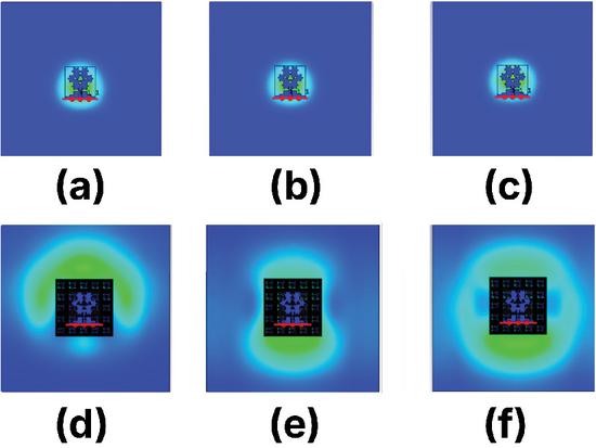
Figure 22 Simulated SAR distributions for the standalone and optimized AMC-backed antenna configurations under 1 W accepted input power normalization: (a)–(c) SAR1g at 1.82, 2.42, and 5.00 GHz; (d)–(f) SAR10g at the corresponding frequencies.
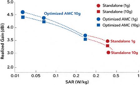
Figure 23 Gain–SAR trade-off comparison between the standalone and optimized AMC-backed antenna configurations for 1 g and 10 g tissue models.
6.3 Gain-SAR trade-Off validation
The gain–SAR trade-off is validated using Table 7 and Fig. 23. The optimized AMC-backed antenna achieves realized gains of 4.12, 4.25, and 4.38 dBi at 1.82, 2.42, and 5.00 GHz, respectively, exceeding the standalone antenna response. This gain improvement is obtained while reducing SAR by nearly one order of magnitude for both 1 g and 10 g averaging models. Thus, the ML-assisted optimization identifies geometries that improve forward radiation while satisfying SAR constraints.
6.4 Discussion of the optimized design
The SAR and radiation results confirm the benefit of combining AMC backing with SAR-aware ML optimization. The AMC reduces surface-wave propagation and backward radiation, while the optimized feed length and AMC-to-antenna air gap regulate near-field current distribution and field confinement. These effects reduce localized SAR hotspots without degrading radiation performance. The optimized AMC-backed antenna maintains radiation efficiency above 87%, showing that SAR reduction is achieved through field redistribution rather than added dissipative loss. Compared with the standalone antenna, the optimized design provides higher gain, improved efficiency, suppressed back radiation, and SAR values below international exposure limits. The present work focuses on SAR-aware AMC-backed antenna optimization using DNN surrogate modeling, NSGA-II optimization, and SHAP interpretation. Detailed bending-cycle tests, multi-position on-body measurements, and long-term motion stability are reserved for future work. Therefore, the wearable claim is limited to SAR-aware, wearable-oriented operation rather than complete garment-level validation.
7 PERFORMANCE COMPARISON
Table 10 compares the proposed antenna with reported AMC-based SAR-reduction designs. Most prior works achieve SAR below 0.4 W/kg but are mainly single- or dual-band and do not include ML-based optimization. In contrast, the proposed design combines a triple-band response at 1.82, 2.42, and 5 GHz with DNN–NSGA-II-based SAR optimization. It achieves SAR values of 0.082 W/kg for 1 g tissue and 0.075 W/kg for 10 g tissue while maintaining a peak realized gain of 4.38 dBi. These results confirm that the ML-optimized MTM-AMC structure improves the gain–SAR trade-off and satisfies IEEE C95.1 and ICNIRP safety limits.
8 CONCLUSION
This work presented a SAR-aware DNN–NSGA-II framework for optimizing an AMC-backed triple-band Sierpinski carpet wearable antenna at 1.82, 2.42, and 5.00 GHz. A 600-sample CST dataset was used to model the relation between geometry, gain, and SAR. The DNN enabled fast prediction, NSGA-II selected Pareto-optimal gain–SAR designs, and SHAP identified feed length and AMC gap as dominant SAR factors, while fractal scaling mainly affected high-frequency gain. The optimized antenna achieved 4.38 dBi peak gain and SAR values of 0.082 W/kg (1 g) and 0.075 W/kg (10 g), satisfying IEEE C95.1 and ICNIRP limits. Future work will study bending, body placement, and deformation stability.
REFERENCES
[1] Y. Thangavelu, B. Thangaraju, and R. Maheswar, “Design and SAR analysis of an AMC-integrated wearable cavity-backed SIW antenna,” Micromachines, vol. 15, no. 12, p. 1530, 2024.
[2] C. Du, L.-R. Pei, J. Zhang, and C.-X. Shi, “A gain enhanced dual-band low SAR AMC-based MIMO antenna for WBAN and WLAN applications,” Progress in Electromagnetics Research M, vol. 115, pp. 21–34, 2023.
[3] A. Flórez Berdasco, M. E. de Cos Gómez, J. Laviada, and F. Las-Heras, “AMC-backed twin arrow antenna for wearable electronic travel aid system at 24 GHz,” IEEE Antennas and Wireless Propagation Letters, vol. 23, no. 11, pp. 3337–3341, 2024.
[4] U. Ali, S. Ullah, A. Basir, B. Kamal, L. Matekovits, and H. Yoo, “Design and SAR analysis of AMC-based fabric antenna for body-centric communication,” IEEE Access, vol. 11, pp. 73894–73911, 2023.
[5] S. Wang and H. Gao, “A dual-band wearable conformal antenna based on artificial magnetic conductor,” International Journal of Antennas and Propagation, vol. 2022, p. 9970477, 2022.
[6] O. M. Youssef, M. El Atrash, and M. A. Abdalla, “A compact fully fabric I-shaped antenna supported with textile-based AMC for low SAR 2.45 GHz wearable applications,” Microwave and Optical Technology Letters, vol. 65, no. 7, pp. 2021–2030, 2023.
[7] W. Bouamra, I. Sfar, A. Mersani, L. Osman, and J.-M. Ribero, “Dual-band textile AMC antenna for WLAN/WBAN applications on the human arm,” International Journal of Electronics and Telecommunications, vol. 68, no. 2, pp. 209–216, 2022.
[8] M. Yadav, M. Ali, and R. P. Yadav, “A compact and economical AMC backed antenna solution for wearable biomedical applications,” International Journal of Microwave and Wireless Technologies, vol. 15, no. 9, pp. 1514–1523, 2023.
[9] N. Sarker, P. Podder, M. R. H. Mondal, S. S. Shafin, and J. Kamruzzaman, “Applications of machine learning and deep learning in antenna design, optimization, and selection: A review,” IEEE Access, vol. 11, pp. 103890–103915, 2023.
[10] D. Sarkar, T. Khan, Jayadeva, and A. A. Kishk, “Machine learning assisted hybrid electromagnetic modeling framework and its applications to UWB MIMO antennas,” IEEE Access, vol. 11, pp. 19645–19656, 2023.
[11] M. R. Khan, C. L. Zekios, S. Bhardwaj, and S. V. Georgakopoulos, “A deep learning convolutional neural network for antenna near-field prediction and surrogate modeling,” IEEE Access, vol. 12, pp. 39737–39747, 2024.
[12] W. Chen, Q. Wu, B. Han, C. Yu, H. Wang, and W. Hong, “Efficient incremental variable-fidelity machine-learning-assisted hybrid optimization and its application to multiobjective antenna design,” IEEE Transactions on Antennas and Propagation, vol. 72, no. 12, pp. 9347–9354, 2024.
[13] T. Naous, A. Al Merie, S. K. Al Khatib, M. Al-Husseini, R. M. Shubair, and H. M. El Misilmani, “Machine learning-aided design of dielectric-filled slotted waveguide antennas with specified sidelobe levels,” IEEE Access, vol. 10, pp. 30583–30595, 2022.
[14] A. Arif, M. Zubair, M. Ali, M. U. Khan, and M. Q. Mehmood, “A compact, low-profile fractal antenna for wearable on-body WBAN applications,” IEEE Antennas and Wireless Propagation Letters, vol. 18, no. 5, pp. 981–985, 2019.
[15] A. N. Alkhafaji, S. M. Abdulsatar, and J. K. Ali, “Design of flexible dual-band tree fractal antenna for wearable applications,” Progress in Electromagnetics Research C, vol. 125, pp. 51–66, 2022.
[16] M. Kaur and J. S. Sivia, “ANN and FA based design of hybrid fractal antenna for ISM band applications,” Progress in Electromagnetics Research C, vol. 98, pp. 127–140, 2020.
[17] B. Hazarika, B. Basu, and A. Nandi, “A wideband, compact, high gain, low-profile, monopole antenna using wideband artificial magnetic conductor for off-body communications,” International Journal of Microwave and Wireless Technologies, vol. 14, no. 2, pp. 194–203, 2022.
[18] W. Thaiwirot, J. Ardhan, S. Prengsri, P. Akkaraekthalin, and S. Chalermwisutkul, “The low-profile all-textile UWB antenna with AMC for WBAN applications,” EURASIP Journal on Wireless Communications and Networking, vol. 2025, no. 1, p. 56, 2025.
[19] T. Messatfa, S. Berhab, F. Chebbara, and M. S. Soliman, “Curvature-adaptive compact triple-band metamaterial uniplanar compact electromagnetic bandgap-based printed antenna for wearable wireless and medical body area network applications,” Processes, vol. 12, no. 7, p. 1380, 2024.
[20] M. Sandhya and L. Anjaneyulu, “Improved wearable, breathable, triple-band electromagnetic bandgap-loaded fractal antenna for wireless body area network applications,” ETRI Journal, vol. 46, no. 4, pp. 571–580, 2024.
[21] U. Ali, S. Ullah, A. Basir, S. Yan, H. Ren, B. Kamal, and L. Matekovits, “Design and performance investigation of metamaterial-inspired dual band antenna for WBAN applications,” PLOS ONE, vol. 19, no. 8, p. e0306737, 2024.
[22] J. Zhang, J. Xu, Q. Chen, and H. Li, “Machine-learning-assisted antenna optimization with data augmentation,” IEEE Antennas and Wireless Propagation Letters, vol. 22, no. 8, pp. 1932–1936, 2023.
[23] M. A. Haque, D. Saha, S. S. Al-Bawri, L. C. Paul, M. A. Rahman, F. Alshanketi, A. Alhazmi, A. H. Rambe, M. A. Zakariya, and S. S. Ba Hashwan, “Machine learning-based technique for resonance and directivity prediction of UMTS LTE band quasi-Yagi antenna,” Heliyon, vol. 9, no. 9, p. e19548, 2023.
[24] Y. Sharma, H. H. Zhang, and H. Xin, “Machine learning techniques for optimizing design of double T-shaped monopole antenna,” IEEE Transactions on Antennas and Propagation, vol. 68, no. 7, pp. 5658–5663, 2020.
[25] L. Cui, Y. Zhang, R. Zhang, and Q. H. Liu, “A modified efficient KNN method for antenna optimization and design,” IEEE Transactions on Antennas and Propagation, vol. 68, no. 10, pp. 6858–6866, 2020.
[26] A. Papathanasopoulos, P. A. Apostolopoulos, and Y. Rahmat-Samii, “Optimization assisted by neural network-based machine learning in electromagnetic applications,” IEEE Transactions on Antennas and Propagation, vol. 72, no. 1, pp. 160–173, 2024.
[27] F. Peng and X. Chen, “An antenna optimization framework based on deep reinforcement learning,” IEEE Transactions on Antennas and Propagation, vol. 72, no. 10, pp. 7594–7605, 2024.
[28] K. Muthukumaravel and S. Santhanam, “Design and optimization of a triple-band fractal antenna with AMC-backing for wearable sub-6 GHz applications,” IETE Journal of Research, 2026.
[29] P. Saha, D. Mitra, and S. K. Parui, “Control of gain and SAR for wearable antenna using AMC structure,” Radioengineering, vol. 30, no. 1, pp. 81–88, 2021.
[30] V. Rajavel and D. Ghoshal, “AMC-based low-profile dual-band slotted patch antenna for IoT devices in the healthcare system,” Iranian Journal of Science and Technology, Transactions of Electrical Engineering, vol. 47, no. 2, pp. 437–450, 2023.
BIOGRAPHIES

Muthukumaravel K received the Bachelor of Engineering degree in Electronics and Communication Engineering from Annamalai University, Chidambaram, Tamil Nadu, India, and the Master of Engineering degree in Applied Electronics from Anna University, Chennai, Tamil Nadu, India. He has more than 12 years of academic experience and is currently serving as an Assistant Professor in the Department of Electronics and Communication Engineering at Meenakshi Ramaswamy Engineering College, Thathanur, Ariyalur, Tamil Nadu, India. His research interests include antenna design and related RF communication systems. He has actively participated in several faculty development programs and completed multiple NPTEL courses.

Suganthi Santhanam received the Bachelor of Engineering degree in Electronics and Communication Engineering from Bharathidasan University, Tiruchirappalli, Tamil Nadu, India, the Master of Engineering degree in Computer and Communication Engineering from Anna University, Chennai, Tamil Nadu, India, and the Ph.D. degree in RF MEMS from Anna University, Chennai. She has more than 25 years of academic experience and is currently serving as a Professor in the Department of Electronics and Communication Engineering at K. Ramakrishnan College of Technology, Tamil Nadu, India. Her research interests include artificial neural networks, digital signal processing, MATLAB-based modeling, computer-aided design of VLSI circuits, and microwave modeling methodologies. She has published more than 30 research articles in SCI- and Scopus-indexed journals and has received research funding from AICTE and ICMR. She has actively participated in and organized several faculty development programs, including Anna University-sponsored FDPs. She is currently guiding research scholars in the areas of wireless sensor networks, image processing, RF device design, photonic networks, and VLSI design.
ACES JOURNAL, Vol. 41, No. 7, 635–649
DOI: 10.13052/2026.ACES.J.410704
© 2025 River Publishers