A Hybrid Triangle–Voxel Model with Local Voxelization for Resolving Diffraction Edge Deficiency in Ray Tracing
Baolai Zhang1, Dan Shi1,*, Jinyu Song1, Xiaoyong Liu1, Hongbo Tao2,*, Huichun Yang3, Zhonghua Xin4, and Yuhao Jia4
1School of Electronic Engineering Beijing University of Posts and Telecommunications, Beijing 100876, China
2024140409@bupt.edu.cn, shidan@bupt.edu.cn, 438182694@qq.com, liuxiaoyong@srtc.org.cn
2State Radio Monitoring Center Testing Center, Beijing 102609, China
taohongbo@srtc.org.cn
3School of Automation Beijing Information Science and Technology University, Beijing 100192, China
52009222@qq.com
4China Coal Research Institute, Beijing 101320, China
en55015@hotmail.com, jiayuhaobuaa@163.com
*Corresponding Authors
Submitted On: March 29, 2026 Accepted On: July 21, 2026
ABSTRACT
Accurate diffraction modeling is essential for ray-tracing-based wireless propagation prediction. The geometric representation of objects in the simulation scene greatly affects diffraction prediction accuracy. Conventional triangular meshes lack the explicit edge information required for diffraction modeling, while global voxelization introduces geometric distortion and substantial computational overhead. This paper presents a hybrid triangle–voxel model that performs local voxelization only within potential diffraction regions (PDR) determined by the first Fresnel zone. The proposed method reconstructs diffraction paths that cannot be captured by pure triangular meshes while preserving triangular facets for direct and reflected rays. Compared with a commercial ray-tracing tool, it achieves an average ray–surface intersection error of 246.4 mm and average path loss, delay, and phase errors of 0.35 dB, 0.12 ns, and 42.0∘, respectively. It also reduces the voxel count and computation time by 60% and 25%. The results show that the proposed model balances diffraction-path recoverability, geometric fidelity, and computational efficiency.
Keywords: Diffraction modeling, hybrid triangle– voxel model, potential diffraction region, ray tracing..
1 INTRODUCTION
As wireless communication systems evolve and the need for reliable radio coverage in complex environments increases [1], accurate modeling of radio frequency propagation has become increasingly important. Diffraction plays a crucial role in non-line-of-sight (NLOS) scenarios, imposing stringent requirements on the physical accuracy and environmental adaptability of wireless propagation models [2, 3].
Among various propagation modeling methods, ray tracing has long been a core technology of wireless propagation prediction [4, 5, 6]. Its theoretical foundations are rooted in geometric optics (GO), geometric diffraction theory (GTD), and uniform diffraction theory (UTD) [7, 8, 9]. Ray tracing approximates the propagation of electromagnetic waves from the transmitter to the receiver as optical rays characterizing multipath components.
Diffraction is essential for accurately characterizing the field strength in NLOS regions [10]. However, the prediction accuracy of UTD-based diffraction strongly depends on well-defined edges in the geometric model [11, 12, 13]. Triangular mesh models are widely used to represent complex surfaces due to their geometric fidelity and storage efficiency. Nevertheless, such smooth triangular surfaces cannot naturally provide the sharp edge structures required for UTD-based diffraction modeling [14]. Degli-Esposti et al. [15] proposed several acceleration techniques for ray-tracing field prediction models, including Fresnel-zone-based spatial filtering that limits intersection calculations to geometrically relevant regions. Fresnel-zone concepts have also been used in UTD-based propagation models to improve the efficiency and accuracy of multiple-diffraction prediction [16]. While such approaches effectively reduce the number of candidate facets involved in ray tracing, they primarily aim at improving computational efficiency on existing geometric models and do not address a fundamental limitation of triangular meshes in diffraction modeling: smooth triangular surfaces reconstructed from real scenes usually lack the explicit sharp edges required by UTD diffraction formulations. Sun et al. [17] proposed a triangular mesh-based edge extraction method using local normal variations and geodesic neighborhoods to segment and preserve sharp features. Bærentzen [18] explored mesh optimization strategies to preserve sharp features. However, these methods are computationally expensive and impractical when dealing with dense, large-scale, or highly irregular realistic models.
In contrast, voxel-based models are well-suited for diffraction modeling using UTD or similar theories because their inherent mesh structure naturally introduces discrete edge and angular features [19]. Amanatides and Woo [20] proposed a fast voxel traversal algorithm that significantly reduces the cost of ray-voxel cross-testing. Díez et al. [21] optimized the surface voxelization of triangular meshes by detecting gaps and enforcing isometric scan lines, thereby achieving higher fidelity voxel surfaces. Despite these advancements, global voxelization of an entire environment still introduces substantial geometric distortion and incurs sharp increases in memory usage and runtime, which limits its applicability to high-precision wireless propagation modeling.
In this paper, a new hybrid triangle-voxel model is proposed that enables efficient diffraction path calculations in ray tracing while maintaining high geometric accuracy. Based on the first Fresnel region, potential diffraction region (PDR) between the transmitter and receiver are identified, and voxelization is performed only within these localized regions. In this way, the proposed representation preserves the surface fidelity required for direct and reflected paths and, at the same time, introduces localized discrete geometric features that are beneficial for diffraction path search. The proposed method yields results highly consistent with those of Wireless InSite (WI) in identifying valid diffraction paths, while reducing the voxelization count by approximately 60% and computation time by approximately 25% compared with global voxelization.
2 HYBRID TRIANGLE-VOXEL MODELING METHODOLOGY
2.1 Triangular mesh model reconstruction
The propagation scenario considered in this study involves a sculpture model surrounded by four transmitters and four receivers. To accurately model the realistic propagation environment, a multi-view 3D reconstruction approach was employed. Specifically, as shown in Fig. 1 (a), multi-view photographs of the sculpture reconstructed using Structure-from-Motion (SfM) and Multi-View Stereo (MVS) techniques in COLMAP, resulting in the point cloud model presented in Fig. 1 (b) [22, 23]. Subsequently, Poisson surface reconstruction was used to convert the point clouds into a digital model suitable for ray tracing simulation. The resulting digital model is composed of a large number of triangular surfaces. Figure 1 (c) shows the triangular model of the sculpture.
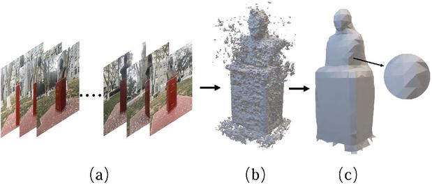
Figure 1 Generation of sculpture triangle mesh model. (a) Dataset. (b) Point cloud model. (c) Triangle mesh model.
As the geometric basis of ray tracing simulation, the reconstructed triangular mesh model not only represents the environment geometry with high accuracy, but also offers efficient storage, making it suited for modeling direct and reflected propagation. However, due to the absence of well-defined diffraction edges, conventional triangular meshes cannot accurately characterize diffraction mechanism in ray tracing.
2.2 Fresnel-guided potential diffraction region selection
In order to accurately describe the diffraction mechanism in ray tracing, it is necessary to identify the regions where diffraction may occur. According to the UTD, diffraction can occur only along shape edges or wedge structures in the propagation environment [24]. However, in the triangular mesh model reconstructed from the real scene, the surfaces are geometrically continuous and lack explicit edges that serve as diffraction boundaries. This makes it difficult for traditional ray tracing algorithm to detect and trace diffraction paths.
To overcome this limitation, a hybrid triangle-voxel model is proposed, which performs local voxelization only in regions where diffraction may occur. These regions, referred to as PDR, are determined based on the first Fresnel region between each transmitter (TX) and receiver (RX) pair [25]. For each triangular surface of the sculpture model, its centroid is denoted as , and the distances from to the TX and RX are defined as follows:
• : the distance from to the transmitter.
• : the distance from to the receiver.
The radius of the first Fresnel zone at point is given by:
| (1) |
where is the wavelength. To provide a flexible PDR selection criterion, a Fresnel-zone threshold factor is introduced. If the shortest distance from the centroid to the line connecting the transmitter and receiver is less than or equal to , the triangular facet is classified as part of the PDR:
| (2) |
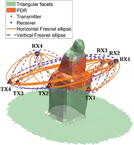
Figure 2 Sculpture model with highlighted PDR regions.
where denotes the shortest distance from to the TX–RX connecting line, and controls the size of the selected PDR. When is smaller than 1, the PDR becomes more compact, which reduces the number of facets to be voxelized but may miss potential diffraction regions near the Fresnel-zone boundary. When is larger than 1, more surrounding facets are included, which improves the robustness of diffraction-edge recovery but increases the voxelization cost. Unless otherwise specified, is used in this work, corresponding to the standard first Fresnel-zone selection. Figure 2 illustrates the potential diffraction zones detected in the statue scene with four transceivers when , and displays the Fresnel zone ellipsoids for each TX-RX pair represented as ellipses in both horizontal and vertical directions. This criterion ensures that diffraction calculations are restricted to the geometrically effective area, thereby avoiding unnecessary global voxelization and reducing computational overhead.
2.3 Local voxelization in PDR
After identifying the PDR, a local voxelization algorithm is applied to convert the corresponding triangular facets into voxel representations. The voxel size is denoted by . A smaller provides finer geometric resolution and more accurate local diffraction edges, but it also increases the number of voxels and the computational cost. In contrast, a larger reduces the voxel count but may introduce stronger staircase distortion and inaccurate edge positions. Therefore, the voxel size should be selected according to the wavelength and the required geometric accuracy. In this work, is chosen to be approximately one-third of the wavelength, which provides a balance between diffraction-edge representation and computational efficiency.
For all vertices of the triangular facets within the PDR, an axis-aligned bounding box (AABB) is first calculated. To avoid boundary truncation during voxelization, the PDR bounding box is further expanded by voxel layers, where denotes the PDR margin layer number. The physical margin can be expressed as
| (3) |
where is the voxel size. A small margin may truncate potential diffraction edges near the PDR boundary, while an excessively large margin increases the local voxelization region and weakens the computational advantage of the proposed method. Therefore, a limited number of margin layers is used to ensure stable edge extraction without significantly increasing the voxel count.
The expanded bounding box is then divided into uniform voxel grids. For each triangular facet in the PDR, a local AABB is further calculated to restrict the range of candidate voxels. Each voxel in this subset is tested using its center point: if the center is within the bounding box of the triangle, the voxel is selected as part of the voxelized representation of the PDR. By traversing all candidate voxels, local voxelization of the PDR is completed, as illustrated in Fig. 3, resulting in a hybrid triangle–voxel representation [26].
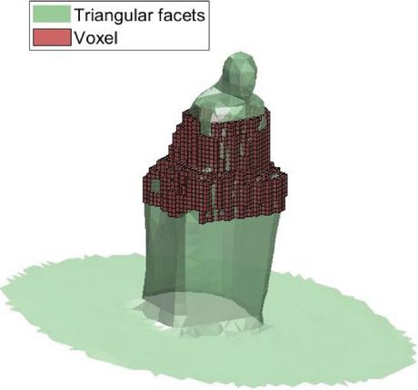
Figure 3 A hybrid triangle-voxel model.
These voxels provide well-defined edges and corners, which serve as the geometric singularities required for formulating diffraction in ray tracing. At the same time, voxelization is applied only to localized regions rather than the entire scene, and the remainder of the environment continues to be represented by triangular meshes. This hybrid representation preserves the geometric fidelity required for accurate direct and reflected ray interactions, while avoiding the substantial computational and memory overhead associated with globally voxelizing the entire model.
2.4 Diffraction treatment on voxel edges within the UTD framework
In the proposed hybrid triangle-voxel model, diffraction is calculated based on the UTD. After local voxelization is performed within the PDR, the intersection lines between adjacent voxel faces are extracted as candidate diffraction edges. Each voxel edge is regarded as an equivalent local wedge edge. For each TX-RX pair, only the voxel edges satisfying the visibility conditions from the transmitter to the edge and from the edge to the receiver are retained for diffraction calculation.
Let , , and denote the positions of the transmitter, receiver, and diffraction point on a valid voxel edge, respectively. The distances from the transmitter to the diffraction point and from the diffraction point to the receiver are expressed as:
| (4) | |
| (5) |
The diffracted electric field at the receiver can be generally written as:
| (6) |
where is the incident electric field at the diffraction point, is the UTD diffraction coefficient determined by the local wedge geometry, is the spreading factor, and is the wavenumber.
Therefore, the voxel edges introduced in the PDR provide the geometric singularities required for UTD-based diffraction modeling. The remaining triangular facets outside the PDR are still used for direct and reflected rays. In this way, the proposed model enables diffraction-path calculation while avoiding the geometric distortion and computational overhead caused by global voxelization.
3 SIMULATION AND ANALYSIS
3.1 Ray-tracing results with the proposed model
In this section, the pure triangular mesh model, the global voxelization model, and the proposed hybrid triangle-voxel model are applied and evaluated on our UTD-Based Ray-Tracing Solver (URTS). Meanwhile, the proposed hybrid model is also implemented on the commercial Wireless InSite platform to further validate its accuracy. The evaluation scenario includes a 3.28-meter-high sculpture placed on a ground plane, with a modeled ground region of 1.5 m in radius, which is mainly composed of three materials: concrete, marble, and gypsum, each modeled with different thicknesses. There are four transmitters and four receivers around the sculpture. As shown in Table 1, the number of PDR facets decreases as the frequency increases because of the reduced Fresnel-zone size, whereas the number of voxels increases significantly when the voxel size is scaled with the wavelength. Considering PDR visibility, diffraction edge resolution, and voxelization cost, the carrier frequency is set to 1 GHz, corresponding to a wavelength of approximately 0.3 m. The voxel size is selected as 0.1 m, which is approximately one-third of the wavelength.
Table 1 Voxelization characteristics under different frequencies
| Freq. | (m) | Voxel | PDR | Voxels |
| Size (m) | Facets | |||
| 0.8 GHz | 0.375 | 0.125 | 638 | 186 |
| 1.0 GHz | 0.300 | 0.100 | 568 | 360 |
| 1.5 GHz | 0.200 | 0.0667 | 448 | 882 |
| 2.4 GHz | 0.125 | 0.0417 | 332 | 2533 |
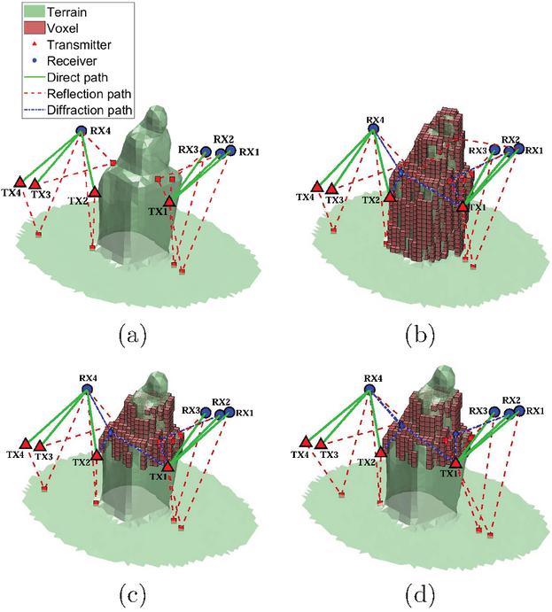
Figure 4 Comparison of URTS and WI ray tracing results under different geometric modeling schemes. (a) URTS simulation using a pure triangular mesh model. (b) URTS simulation using global voxelization model. (c) URTS simulation using a hybrid triangle-voxel model. (d) WI simulation using a hybrid triangle-voxel model.
Figure 4 (a) shows the ray tracing results using the pure triangular mesh representation, where only six direct paths and seven reflected paths are observed. This is because, in the UTD method, diffraction can only occur at explicitly defined geometric edges, which are used to locate diffraction points, compute diffraction coefficients, and characterize the diffracted rays. However, the pure triangular mesh approximates the sculpture with smooth, continuously connected surfaces, making it impossible to locate valid diffraction edges and therefore yielding no diffraction paths. Figure 4 (b) shows the results obtained with full voxelization. Because each voxel provides well-defined boundaries and sharp edges, three diffraction paths are successfully detected. However, full voxelization produces faceted, staircase surfaces, which generate additional non-physical reflection paths due to the discretized geometry. Figure 4 (c) illustrates the results of the proposed local voxelization scheme, which preserves the geometric continuity of most surfaces while still providing discrete edges in the diffractive regions. Consequently, the physically valid diffraction paths are retained, and the spurious reflections introduced by full voxelization are effectively eliminated. Finally, Fig. 4 (d) presents the results obtained using the WI platform under the same local voxelization configuration, which closely match the URTS results in both path count and spatial distribution, demonstrating that the proposed hybrid modeling approach is applicable to different ray-tracing platforms and yields consistent propagation behavior across them.
3.2 Model accuracy analysis
The geometric distortion of the model surface directly affects the accuracy of ray–surface intersection prediction, which is critical for reliable ray tracing computation. To quantitatively assess the geometric fidelity of the proposed hybrid triangle-voxel representation, the root mean square surface distance (RMSD) between the voxelized model and the original triangular mesh is evaluated using the pure triangular surface model as the reference. The RMSD is defined as:
| (7) |
where denotes the number of sampling points uniformly distributed on the surface of the original triangular mesh, and represents the shortest distance from sampling point to the surface of the voxelized model. A total of 10,000 sampling points are uniformly distributed over the mesh surface. For each sampling point , the shortest distance to the voxelized surface is computed. The mean squared distance (MSD) is then obtained by averaging all values, and its square root yields the root mean square deviation (RMSD), which quantifies the global surface deviation. A smaller RMSD indicates a closer match to the reference geometry and thus less geometric distortion.
Figure 5 shows a quantitative comparison of the mean distance, median distance, and RMSD between the global voxelized and the proposed hybrid triangle–voxel models. All evaluated error metrics of the hybrid model are lower than those of the global voxel model. In particular, the RMSD is reduced by approximately 7% compared to the global voxelization, indicating that local voxelization more accurately preserves the original surface geometry. The hybrid model effectively reduces local surface distortion, which in turn improves the accuracy of ray–surface intersection prediction in ray-tracing propagation simulations.
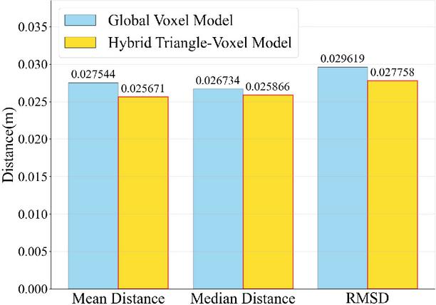
Figure 5 Quantitative comparison of the mean distance, median distance, and RMSD between the global voxelization model and the hybrid triangle–voxel model.
In addition to geometric fidelity, the accuracy of the diffraction path generated by the application of the hybrid model is verified by comparing and analyzing the spatial deviation of ray-surface intersection points along the propagation paths obtained from URTS and WI. For each pair of corresponding intersection points along a propagation path, the 3D Euclidean distance is calculated. These pointwise errors are then averaged to obtain the path-level mean error , expressed as:
| (8) |
where is the number of intersections on the path. The overall average error is obtained by further averaging the path-level mean errors of all reflection and diffraction paths:
| (9) |
Figure 6 summarizes the results. The fifth reflection path exhibits the largest deviation of 402.7 mm due to its high sensitivity to geometric displacement, whereas the diffraction paths show smaller errors. Most path errors fall within ±1 standard deviation of the mean, as indicated by the red shaded area. The average intersection error between URTS and WI is 246.4 mm.
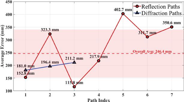
Figure 6 Mean errors of ray–surface intersections for reflection and diffraction paths.
In addition, the path loss error, delay error, and phase error of the three dominant diffraction paths are calculated. The path loss error is defined as the absolute difference between the path losses predicted by URTS and WI. Since the same transmitted power and antenna configurations are used in both platforms, this metric is equivalent to the received-power deviation of the corresponding path. The delay error is obtained from the difference between the total propagation delays of the corresponding paths, while the phase error is calculated from the path-length difference normalized by the wavelength and wrapped into the range of to .
Table 2 Propagation-domain errors of diffraction paths
| Path | Path Loss | Delay | Phase |
| Error (dB) | Error (ns) | Error (deg) | |
| D1 | 0.18 | 0.08 | 28.8 |
| D2 | 0.34 | 0.11 | 39.6 |
| D3 | 0.52 | 0.16 | 57.6 |
| Mean | 0.35 | 0.12 | 42.0 |
Table 2 summarizes the propagation-domain errors of the three dominant diffraction paths. The average path loss error is 0.35 dB, and the maximum path loss error is 0.52 dB. The average delay error is 0.12 ns, corresponding to a small path-length deviation of approximately 36 mm. The average phase error is , and the maximum phase error is . Since phase is highly sensitive to path-length differences at 1 GHz, these results are acceptable for diffraction-path validation. Overall, the proposed hybrid triangle–voxel model preserves the main spatial, power, delay, and phase characteristics of diffraction paths while maintaining high geometric fidelity, thereby demonstrating its physical reliability for diffraction modeling.
3.3 Computational efficiency and complexity analysis
To evaluate the computational efficiency of the proposed method, experiments were performed on a workstation equipped with an Intel (R) Core (TM) i9-14900K CPU @ 3.20 GHz and an NVIDIA GeForce RTX 3090 GPU. The sculptural model used in the experiments contains 3383 triangular faces. Table 3 summarizes the voxel counts, peak memory usage, and preprocessing time for both global and local voxelization schemes. Compared with the global voxelization (887 voxels), the local voxelization scheme uses only 360 voxels, achieving a 60% reduction in voxel count, a 25% decrease in computation time, and slightly lower peak memory consumption. Although the performance improvement may appear moderate due to the small-scale test scene, the acceleration is expected to be more significant in larger environments, where global voxelization would require substantially more voxels.
Table 3 Computational cost comparison of global and local voxelization
| Model | Number | Memory | Computation |
| of Voxels | Usage (MB) | Time (s) | |
| Full Voxelization | 887 | 34.9219 | 53 |
| Local Voxelization | 360 | 33.7891 | 40 |
4 CONCLUSION
This paper presents a hybrid triangle–voxel model for efficient diffraction modeling in ray tracing. By identifying potential diffraction regions based on the first Fresnel-zone criterion and applying local voxelization only within these regions, the proposed method preserves geometric fidelity while reducing voxel count by 60% and computation time by 25%. Simulation results show close agreement with those from commercial software, with an average ray–surface intersection error of 246.4 mm. For the dominant diffraction paths, the average path loss error, delay error, and phase error are 0.35 dB, 0.12 ns, and 42.0∘, respectively. These results demonstrate that the proposed model preserves the main spatial, power, delay, and phase characteristics of diffraction paths while maintaining computational efficiency. The proposed model provides a physically interpretable approach for improving UTD-based diffraction prediction in reconstructed triangular-mesh scenarios. Future work will extend the validation to larger indoor and urban environments under different frequency bands.
ACKNOWLEDGMENT
This work was supported by the Beijing Municipal Natural Science Foundation (L233017), the National Key Laboratory of Intelligent Coal Mining and Strata Control (SKLIS202407), and the MIIT Key Laboratory of Radio Spectrum Monitoring Technology (SRTC-KFKT202501).
REFERENCES
[1] H. Jiang, M. Mukherjee, J. Zhou, and J. Lloret, “Channel modeling and characteristics for 6G wireless communications,” IEEE Network, vol. 35, no. 1, pp. 296–303, Jan. 2021.
[2] G. Duggal, A. M. Kumar, R. M. Buehrer, H. S. Dhillon, N. Tripathi, and J. H. Reed, “Impact of frequency on diffraction-aided wireless positioning,” in 2025 IEEE International Conference on Communications Workshops (ICC Workshops), pp. 1457–1463, 2025.
[3] F. Fuschini, E. M. Vitucci, M. Barbiroli, G. Falciasecca, and V. Degli-Esposti, “Ray tracing propagation modeling for future small-cell and indoor applications: A review of current techniques,” Radio Science, vol. 50, no. 6, pp. 469–485, 2015.
[4] J. Zhang, J. Lin, P. Tang, W. Fan, Z. Yuan, X. Liu, H. Xu, Y. Lyu, L. Tian, and P. Zhang, “Deterministic ray tracing: A promising approach to THz channel modeling in 6G deployment scenarios,” IEEE Communications Magazine, vol. 62, no. 2, pp. 48–54, 2024.
[5] D. Shi, N. Lv, N. Wang, and Y. Gao, “An improved shooting and bouncing ray method for outdoor wave propagation prediction,” Applied Computational Electromagnetics Society (ACES) Journal, vol. 32, no. 7, pp. 581–585, July 2017.
[6] D. Shi, N. Lv, and Y. Gao, “A diffraction ray tracing method based on curved surface ray tube for complex environment,” Applied Computational Electromagnetics Society (ACES) Journal, vol. 32, no. 7, pp. 608–613, July 2017.
[7] J. B. Keller, “Geometrical theory of diffraction,” Journal of the Optical Society of America, vol. 52, no. 2, pp. 116–130, Feb. 1962.
[8] R. G. Kouyoumjian and P. H. Pathak, “A uniform geometrical theory of diffraction for an edge in a perfectly conducting surface,” Proceedings of the IEEE, vol. 62, no. 11, pp. 1448–1461, Nov. 1974.
[9] F. Weinmann, “UTD shooting-and-bouncing extension to a PO/PTD ray tracing algorithm,” Applied Computational Electromagnetics Society (ACES) Journal, vol. 24, no. 3, pp. 281–293, June 2009.
[10] S. Li, G. Cui, S. Guo, C. Jia, L. Kong, and X. Yang, “On the electromagnetic diffraction propagation model and applications,” IEEE Journal of Selected Topics in Applied Earth Observations and Remote Sensing, vol. 13, pp. 884–889, 2020.
[11] K. W. Kim, M. D. Kim, J. Lee, J. J. Park, Y. K. Yoon, and Y. J. Chong, “Millimeter-wave diffraction-loss model based on over-rooftop propagation measurements,” ETRI Journal, vol. 42, no. 6, pp. 827–836, 2020.
[12] S. Deng, G. R. MacCartney, and T. S. Rappaport, “Indoor and outdoor 5G diffraction measurements and models at 10, 20, and 26 GHz,” in 2016 IEEE Global Communications Conference (GLOBECOM), pp. 1–7, 2016.
[13] J. Y. Lee, J. H. Lee, and S. C. Kim, “Improving the accuracy of millimeter-wave ray-tracing simulations by modeling roadside trees,” IEEE Antennas and Wireless Propagation Letters, vol. 18, no. 1, pp. 162–166, 2019.
[14] R. Chen, M. Hua, S. He, Y. Zhang, and G. Zhu, “UTD solution for diffraction by anisotropic impedance wedge with arbitrary exterior wedge angle under arbitrary skew incidence,” IEEE Antennas and Wireless Propagation Letters, pp. 1–5, 2025.
[15] V. Degli-Esposti, F. Fuschini, E. M. Vitucci, and G. Falciasecca, “Speed-up techniques for ray tracing field prediction models,” IEEE Transactions on Antennas and Propagation, vol. 57, no. 5, pp. 1469–1480, 2009.
[16] M. B. Tabakcioglu, D. Ayberkin, and A. Cansiz, “Comparison and analyzing of propagation models with respect to material, environmental and wave properties,” Applied Computational Electromagnetics Society (ACES) Journal, vol. 29, no. 6, pp. 486–491, June 2014.
[17] Y. Sun, D. L. Page, J. K. Paik, A. Koschan, and M. A. Abidi, “Triangle mesh-based edge detection and its application to surface segmentation and adaptive surface smoothing,” in Proceedings International Conference on Image Processing, vol. 3, pp. 825–828, 2002.
[18] J. A. Bærentzen, “Optimizing 3D triangulations to recapture sharp edges,” Tech. Rep. 11, IMM, DTU Compute, Lyngby, Denmark, 2006.
[19] I. Tropkina, A. Pyattaev, Y. Sadovaya, and S. Andreev, “Modeling of SHF/EHF radio-wave scattering for curved surfaces with voxel cone tracing,” IEEE Antennas and Wireless Propagation Letters, vol. 21, no. 2, pp. 426–430, 2021.
[20] J. Amanatides and A. Woo, “A fast voxel traversal algorithm for ray tracing,” Proc. Eurographics ’87, pp. 3–10, 1987.
[21] S. D. Díez, C. C. Somolinos, and S. R. G. Palomo, “Optimizing surface voxelization for triangular meshes with equidistant scanlines and gap detection,” Computer Graphics Forum, vol. 43, no. 6, p. e15195, 2024.
[22] J. L. Schonberger and J. M. Frahm, “Structure-from-motion revisited,” in Proceedings of the IEEE Conference on Computer Vision and Pattern Recognition, pp. 4104–4113, 2016.
[23] J. L. Schönberger, E. Zheng, J. M. Frahm, and M. Pollefeys, “Pixelwise view selection for unstructured multi-view stereo,” in European Conference on Computer Vision, pp. 501–518, 2016.
[24] T. Hashimoto, X. Zhang, and C. D. Sarris, “Heuristic UTD diffraction coefficient for three-dimensional dielectric wedges,” IEEE Transactions on Antennas and Propagation, vol. 69, no. 8, pp. 4816–4826, 2021.
[25] T. S. Rappaport, “Wireless communications–principles and practice,” Microwave Journal, vol. 45, no. 12, pp. 128–129, 2002.
[26] E. Eisemann and X. Décoret, “Fast scene voxelization and applications,” in Proceedings of the 2006 Symposium on Interactive 3D Graphics and Games, pp. 71–78, 2006.
BIOGRAPHIES

Baolai Zhang received the bachelor’s degree in electronic information engineering from Civil Aviation University of China, Tianjin, China, in 2024. He is currently working toward the master’s degree in new generation of electronic information technology with the Beijing University of Posts and Telecommunications, Beijing, China. His research interests include ray tracing and 3D reconstruction.

Dan Shi received the Ph.D. degree in electronic engineering from Beijing University of Posts and Telecommunications, Beijing, China, in 2008. She is a Professor with Beijing University of Posts and Telecommunications. Her research interests include electromagnetic compatibility, electromagnetic environment, and electromagnetic computation.

Jinyu Song received the bachelor’s degree in electronic science and technology from Beijing University of Chemical Technology, Beijing, China, in 2024. He is currently working toward the master’s degree in new generation of electronic information technology with Beijing University of Posts and Telecommunications, Beijing, China. His research interests include ray tracing, 3D reconstruction, and electromagnetic compatibility.

Xiaoyong Liu received the bachelor’s degree in radio technology and information system from Tsinghua University, Beijing, China, in 2002. He is currently working toward the doctoral degree in electronic science and technology with the Beijing University of Posts and Telecommunications, Beijing, China. His research interests include electromagnetic compatibility, testing and measurement, and radio frequency spectrum technology.

Hongbo Tao received the Ph.D. degree in electronic engineering from Beijing University of Posts and Telecommunications, Beijing, China, in 2003. Currently, he works at the National Radio Monitoring Center. His research interests include radio detection technology, electromagnetic compatibility analysis, and specialized radio measuring instruments.

Huichun Yang received the Ph.D. degree in electronic engineering from Beijing University of Posts and Telecommunications, Beijing, China, in 2012. Her research interests include electromagnetic compatibility and antenna design.

Zhonghua Xin received the master’s degree from Beijing Technology and Business University, Beijing, China, in 2002. She is a senior engineer with the Coal Science and Technology Research Institute. Her research interests include electromagnetic compatibility of mining electrical equipment and wireless equipment, and the electromagnetic environment of underground coal mines.

Yuhao Jia received the bachelor’s degree in information and computing science from Beihang University, Beijing, China, in 2020, and the master’s degree in electronic information engineering from City University of Hong Kong, Hong Kong, China, in 2023. He is currently a researcher with China Coal Research Institute (CCRI), Beijing, China. His research interests include intelligent detection technology and electromagnetic compatibility.
ACES JOURNAL, Vol. 41, No. 7, 678–686
DOI: 10.13052/2026.ACES.J.410708
© 2026 River Publishers