Optimization and Simulation of Auxiliary Magnetic Barrier Permanent Magnet Synchronous Machine for Wind Turbine
Chunyu Qu*, Zidi Ge, Chuhan Yang and Xiuping Wang
Shenyang Institute of Engineering, Shenyang 110136, China
E-mail: qu434@163.com
*Corresponding Author
Received 09 September 2021; Accepted 10 October 2021; Publication 08 December 2021
Abstract
The auxiliary magnetic barrier permanent magnet synchronous motor (AMBPMSG) has not only the advantages of high power density and high efficiency of permanent magnet synchronous generator, but also the advantages of high temperature non-demagnetization and low cost of the reluctance motor. It has a broad application prospect in the field of wind power generation. Statement is presented in this paper, on the basis of structure and operation principle of the motor, the magnetic barrier surrounding the shape, shape of magnetic bridge, magnetic barrier layer and a permanent magnet is optimized, by means of two-dimensional finite element simulation software analysis of air-gap magnetic field, the counter electromotive force, reduce no-load back electromotive force harmonic content, in order to obtain the optimal electromagnetic performance, and develop the visual design and simulation platform software. The research of this paper has a certain reference value for the popularization and application of AMBPMSG.
Keywords: Permanent magnet wind turbine, auxiliary magnetic barrier, back electromotive force, parameter optimization.
Introduction
Wind power generation is a widely used power generation technology nowadays [1–4]. It is a power generation method that converts the kinetic energy contained in the wind into electric energy. As the heart of wind power generation, wind turbine takes on the task of converting mechanical energy into electric energy, which directly affects the energy efficiency and power supply quality in the process of energy conversion [5–10]. Wind turbines are mainly composed of blades, generators, mechanical parts and electrical parts. At present, wind turbines mainly use ordinary three-phase synchronous generators (TSG) and permanent magnet synchronous generators (PMSG). The stator side of TSG is connected with the power grid through a frequency converter. The rotor side adjusts the excitation current of the generator through an excitation controller to control the output voltage amplitude of the stator side of the generator, which forms a variable speed constant frequency synchronous wind power generation system. The PMSG rotor is directly coupled with the wind turbine, and the output voltage and frequency of the generator change with the change of wind speed. PMSG is widely used in wind power generation due to its high efficiency, high power factor, low maintenance cost and mature power generation technology. However, PMSG still has the following problems [11–20]:
(1) It is difficult to maintain the full power converter.
(2) The amount of permanent magnetic materials is large, and the price of rare earth permanent magnetic materials is expensive.
(3) Permanent magnet is prone to demagnetization at high temperature and vibration, and irreversible demagnetization occurs under the impact of overcurrent, which may cause the motor to be scrapped.
Therefore, this paper introduces an auxiliary magnetic barrier permanent magnet synchronous generator (AMBPMSG). The stator part of the machine adopts the stator structure of asynchronous machine, and the rotor part combines the characteristics of permanent magnet machine and reluctance machine. It has the advantages of high efficiency while saving permanent magnet material. In the past 20 years, with the continuous progress of wind power technology, the capacity of wind power unit is also increasing, and the technology has gradually matured. Many scholars have a certain research on permanent magnet wind generator.
Literature [21] proposed a new scheme of double-stator permanent magnet integrated starting generator and established its mathematical model, which improved the performance of integrated starting and generating machine applied to hybrid electric vehicles. Literature [22] put forward a series double hybrid direct drive machine stator magnetic circuit structure, the double stator structure used in the hybrid variable reluctance machine, and study of the magnetic circuit structure, this new type of machine are calculated and analyzed under different working condition of machine parameters and operation features, for the stator permanent magnet machine design and optimization provides certain experience. Literature [23] takes the permanent magnet wind turbine in 4.8 MW as the research object, and carries out simulation analysis and calculation on the generator’s no-load, rated load and short-circuit conditions. Finally, based on the loss in the electromagnetic design scheme, using the theory of engineering heat transfer, the heat transfer characteristics and temperature rise inside the generator are analyzed, which provides a theoretical basis for the electromagnetic design and structure optimization of the generator.
All the above literatures have analyzed the electromagnetic and structural characteristics of PMSM with different structures, which has made a certain contribution to the promotion of the machine. However, a comprehensive and complete structural optimization is still needed for AMBPMSG, and an electromagnetic calculation and simulation platform is developed to further improve the operation performance and accelerate the pace of its application. This paper optimizes the new auxiliary magnetic barrier permanent magnet synchronous motor, and designs the design software platform, which is innovative.
1 Equivalent Magnetic Circuit and Operating Principle of AMBPMSG
The Equivalent Magnetic Circuit of AMBPMSG
With the development of industrial technology and the popularization of computers, the magnetic circuit solving method of permanent magnet synchronous machine has changed from graphic method to perfect method which corrects various coefficients obtained by electromagnetic calculation and experimental verification. In order to simplify the calculation, the following assumptions are required to establish the equivalent magnetic circuit model [24]:
(1) All air parts are vacuum;
(2) The permeability of permanent magnet is equal to the permeability of vacuum;
(3) The magnetomotive force generated by the permanent magnet is ignored;
(4) Ignore the stator core reluctance.
The three-layer auxiliary magnetic barrier structure model is taken as an example to analyze the equivalent magnetic circuit of D-axis and Q-axis. The magnetic force lines of D-axis and Q-axis of AMBPMSM start from the stator yoke and successively pass through the air gap, the magnetic conductive layer between adjacent magnetic barriers, the air gap, the stator tooth and the stator yoke [8]. As shown in Figures 1 and 2, according to the trend of magnetic force lines, the equivalent magnetic circuit model of D-axis and Q-axis and the equivalent magnetic circuit are obtained.
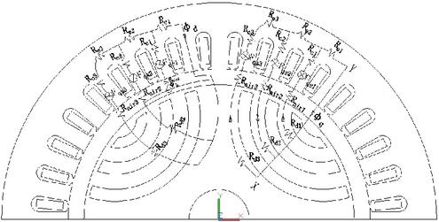
Figure 1 Equivalent magnetic circuit model of the D-axis and Q-axis of AMBPMSG.
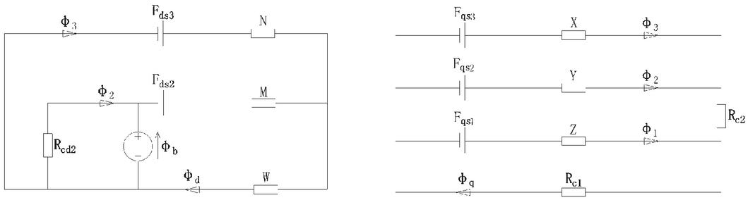
Figure 2 Equivalent magnetic circuit diagrams of the D-axis and Q-axis of AMBPMSG.
Among them, the is the stator yoke magnetic resistance; is the stator tooth magnetic resistance; is the sum of the reluctance of the air magnetic barrier and the magnetic conductive block; is the magnetomotive force generated by the stator winding coil; is the magnetic flux of the D-axis; is the reluctance of the rotor magnetic channel; is the magnetomotive force generated by the stator winding coil; is the sum of magnetic flux in the direction of Q-axis, and the expressions of N, M, W, X, Y and Z are:
| (1) | ||
| (2) | ||
| (3) | ||
| (4) | ||
| (5) | ||
| (6) |
Based on KCL and KVL laws, the equation can be written as follows:
| (7) | |
| (8) | |
| (9) | |
| (10) | |
| (11) | |
| (12) |
Among them:
| (13) | ||
| (14) | ||
| (15) | ||
| (16) | ||
| (17) | ||
| (18) |
According to Equations (7), (8), (13), (14) and (15), the magnetic flux of D-axis can be obtained, and then the inductance of D-axis can be obtained according to the winding turns and current. According to Equations (9), (16), (17) and (18), the magnetic flux in the direction of Q-axis can be obtained, and then the inductance of Q-axis can be obtained according to the number of turns and current of the stator winding.
1.1 The Structure and Operating Principles of AMBPMSG
As shown in Figure 3, AMBPMSG is composed of a fixed stator and a rotating rotor. The stator is the same as the traditional asynchronous machine, and the rotor is combined with the features of a built-in permanent magnet synchronous machine and a synchronous reluctance machine. During the operation of the generator, relative motion is generated between stator windings and permanent magnet magnetic field, and regular alternating three-phase sinusoidal electromotive force is induced in the windings, which can be used as a power supply to connect the load or upload to the grid. The mechanical speed of the rotor of the machine is consistent with the speed of the rotating magnetic field. In the structure of the actual generator, the part of the excitation magnetic field can be rotated, and the part of the armature winding used for induction can be rotated, as long as the two can generate relative motion. Synchronous generator is widely used in nuclear power, thermal power, hydropower and current wind power. When its magnetic pole logarithm is p and rotor speed is n, the output current frequency .

Figure 3 Schematic diagram of permanent magnet synchronous generator.
Traditional generators used in hydropower, thermal power and other places usually use electric excitation winding to establish magnetic field. But in wind turbines synchronous generators using permanent magnets to establish magnetic field have been widely used. The magnetic field of permanent magnet is constant, so it is difficult to adjust the main magnetic field from the outside, but nowadays, with the rapid development of power electronics technology, relevant adjustment can be made from the stator electric quantity.
2 Electromagnetic Solutions of AMBPMSG
Based on the machine design theory and combined with the index parameters, the main parameters of the machine are determined by the magnetic circuit calculation method as shown in Table 1.
Table 1 Main parameters of machine
| Parameter | Value | Parameter | Value |
| Stator outer diameter | 260 mm | Pole-pairs | 3 |
| Stator Bore | 180 mm | Number of slots | 36 |
| Rotor outer diameter | 179 mm | Core length | 110 mm |
| Rotor inner diameter | 60 mm | Thickness of permanent magnet | 7.85 mm |
| Rated power | 7.5 kW | Magnetization direction length | 2.41 mm |
| Rated speed | 1000 rpm | Air gap length | 0.5 mm |
| Rated phase voltage | 220 V | Polar arc coefficient | 0.7 |
| Rated phase current | 14 A | Silicon steel sheet material | DW460-50 |
| Rated torque | 71.63 Nm | Permanent magnet material | NdFe36 |
| Rated frequency | 50 Hz | Stator resistance | 0.53 |
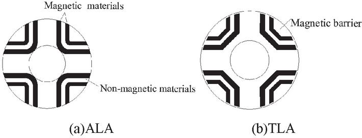
Figure 4 AMBPMSG rotor punching structure.
2.1 Magnetic Barrier Structure Design
AMBPMSG rotor stamping is formed in the same way as synchronous reluctance machines, mainly consisting of axial laminated rotor structure (ALA) and ramming laminated rotor structure (TLA), as shown in Figure 4. ALA alternately superimposes magnetic materials and non-magnetic materials along the axial direction according to a certain thickness ratio. The highly anisotropic laminated magnetic permeability improves the convex pole ratio, resulting in high torque density and power factor. However, due to the complex processing technology and low mechanical strength, it cannot be applied in the industrial field on a large scale [9]. TLA further improves the power factor and efficiency of the machine by stamping the air magnetic barrier in the silicon steel sheet to increase the inductance difference between D and Q axes. However, since ALA rotor structure is not suitable for mass production [10], TLA rotor structure is adopted in this design.
(1) Determine the shape of the magnetic barrier
AMBPMSG commonly used magnetic barrier shapes are mainly U-shaped and C-shaped, as shown in Figure 5. As the magnetic density distribution in the U-shaped magnetic barrier structure varies greatly, local saturation may occur, leading to the increase of machine magnetic flux leakage, the reduction of salient pole ratio, and the reduction of torque at load, so this design adopts the C-shaped magnetic barrier structure. At the same time, the part near the air gap at both ends of the magnetic barrier is thinner, and the middle part of the magnetic barrier is thicker. In this way, the thickness of the magnetic barrier is not only sufficient to isolate the magnetic field, but also can reduce the cogging torque ripple caused by the slotting of the stator rotor [11].
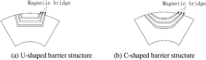
Figure 5 Common magnetic barrier structures.
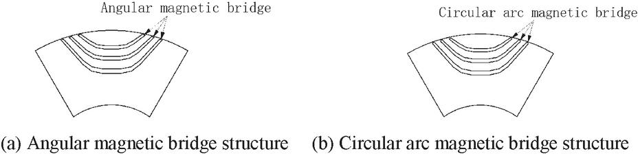
Figure 6 Common magnetic bridge structures.
(2) Peripheral magnetic bridge shape selection
AMBPMSG commonly used angular magnetic bridge structure and circular arc magnetic bridge structure, as shown in Figure 6. If the number of magnetic barrier layers is small () and the thickness of each layer is large, when the magnetic barrier is aligned with the stator teeth, a large magnetoresistance will be generated. The torque ripple caused by this non-uniform reluctance is dominant. In this case, the use of arc-shaped magnetic bridge can weaken the torque ripple. When magnetic barrier layer is more ( or higher), each layer of magnetic barrier thickness is small, the stator tooth thickness is often greater than the thickness of the magnetic barrier, when a layer of magnetic barrier with the stator tooth alignment, the field lines will not be cut off completely, this caused by the torque ripple of cross coupling effect dominates, the angle type magnetic bridge is adopted can reduce the torque ripple [12].
In this design, in order to increase the inductance difference between D-axis and Q-axis, and improve the salient pole rate, the rotor adopts a multi-layer magnetic barrier structure. Therefore this design uses the angular magnetic bridge structure.
(3) Selection of barrier layers
In order to reduce the complexity of the design of magnetic barrier parameters and reduce the number of magnetic barrier parameters to be optimized, the air magnetic barrier can be regarded as the uniform slotting effect of the rotor, and the distance between the two adjacent ends of the rotor is controlled to be consistent. By restricting the relationship between magnetic barrier parameters, the number of parameters to be optimized for the machine is greatly reduced, so as to realize the rapid design of the machine. The traditional uniformly distributed magnetic barrier parameter design adopts the magnetic barrier Angle constraint mode [13], and the constraint relation is:
| (19) |
Wherein is the distance Angle between the two adjacent magnetic barriers, is the Angle of the first layer of magnetic barriers, both of which satisfy the above equation. “” is the number of magnetic barrier layers, and “p” is the polar logarithm. Therefore, the number of magnetic barrier layer is selected below. The finite element models when , , , and were established respectively. When there was only air in the magnetic barrier, the three-phase sinusoidal alternating current with an effective value of 14A was introduced. The finite element models in various cases were shown in Table 2.
Table 2 Finite element models of different magnetic barrier layers
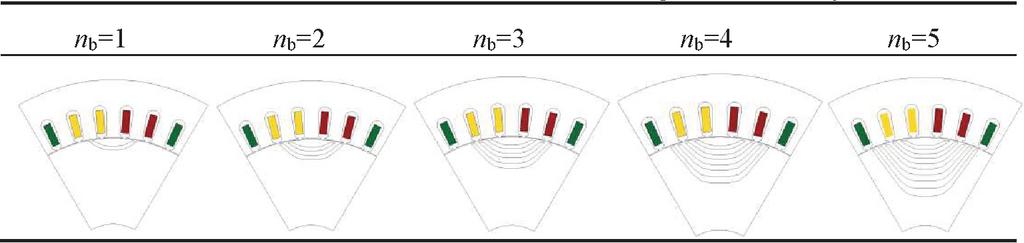 |
For permanent magnet generators, the back electromotive force harmonics will generate additional losses in the stator windings, the rotor loop and the iron core, which will reduce the overall energy conversion efficiency of the machine. Therefore, it is very necessary to analyze the back electromotive force harmonics of permanent magnet generators. As shown in Figure 7, the column diagram of load back electromotive force harmonic decomposition is shown.
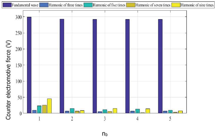
Figure 7 Inverse back electromotive force harmonic bar diagram.
It can be seen that when the number of magnetic barrier layers increases, the odd harmonics of the machine are reduced to some extent. If the pilot runs under the state of serious third and fifth harmonics for a long time, vibration noise, local overheating and temperature rise will be generated, which will lead to accelerated aging of the insulation layer and greatly reduce the service life of the machine [14]. It can be seen that the third and fifth harmonics are relatively small when the number of magnetic barrier layer . To sum up, from the point of increasing the load torque and reducing the odd harmonic of the load reverse electromotive force, the number of magnetic barrier layer is selected. At this point, the parameters of each part of the magnetic barrier are shown in Figure 8.
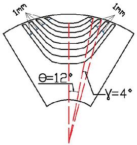
Figure 8 Magnetic barrier Angle constraint parameter.
2.2 Determination of Permanent Magnet Proportion and Magnetizing Direction
The proportion of permanent magnet K(%) is defined as the proportion of permanent magnet in the air magnetic barrier. As shown in Figure 9, when , the permanent magnet is gradually filled with 12.5% in the air magnetic barrier until .
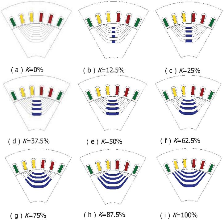
Figure 9 Different structure diagrams of K.
Meanwhile, the magnetizing direction of the permanent magnet was changed to the positive X-axis and the positive Y-axis respectively. The changes of efficiency in the process were analyzed, as shown in Figure 10.
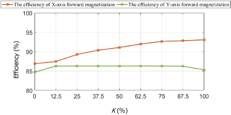
Figure 10 The efficiency with different magnetizing direction and K.
It can be seen that the permanent magnet is not fully utilized when the Y-axis is in positive magnetization. When the X-axis is in positive magnetization, the eat a better pie increases with the increase of K, while when , Tr is smaller and higher. Therefore, the magnetization direction is in the positive direction of X-axis, and the proportion of permanent magnet . The magnetic field lines and local amplification of magnetic density are shown in Figure 11. It can be seen that the magnetic field lines of AMBPMSG are trending correctly, and the magnetic density is slightly saturated locally but has little impact.
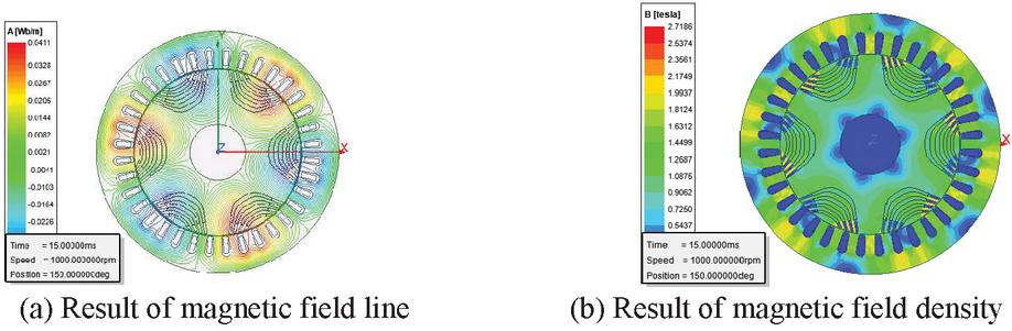
Figure 11 AMBPMSG finite element model.
AMBPMSG’s counter electromotive force is shown in Figure 12. AMBPMSG’s inverse electromotive force presented sinusoidal distribution and its effective value was close to 220V. Due to the tooth groove effect between the stator opening slot and permanent magnets, the waveform of no-load back electromotive force is not standard sine, but all show saw tooth depression at the crest [15]. Meanwhile, the distortion degree of AMBPMSG’s waveform is slightly lower than that of the other two structures, which improves the stability of machine operation and the utilization rate of permanent magnet materials.
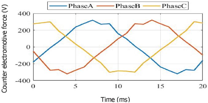
Figure 12 AMBPMSG counter electromotive force.
3 Rotor Structure Optimization of AMBPMSG
3.1 Helical Rotor Pole
Cogging torque refers to the torque produced by the interaction between the armature winding core and the permanent magnet of the rotor, which is an inherent phenomenon of permanent magnet machines [16]. The presence of cogging torque will make the machine produce vibration and noise and increase the load torque ripple, while the no-load back electromotive force affects the running stability of the machine. If measures can be taken to reduce the effective value of cogging torque and the distortion rate of no-load back electromotive force, the running stability of the machine under load will be improved.
Due to the complex processing technology of continuous inclined pole, it is difficult to realize, so the piecewise inclined pole method is adopted in this paper. The relationship between the optimal inclined pole Angle and the number of sections n is as follows [17]:
| (20) |
Where LCM () represents the minimum common multiple of the number of slots for the stator and the number of poles for the rotor. When the number of segments , 3, 5 and 7, the tooth torque waveform and no-load back electromotive force harmonic decomposition are shown in Figure 13.
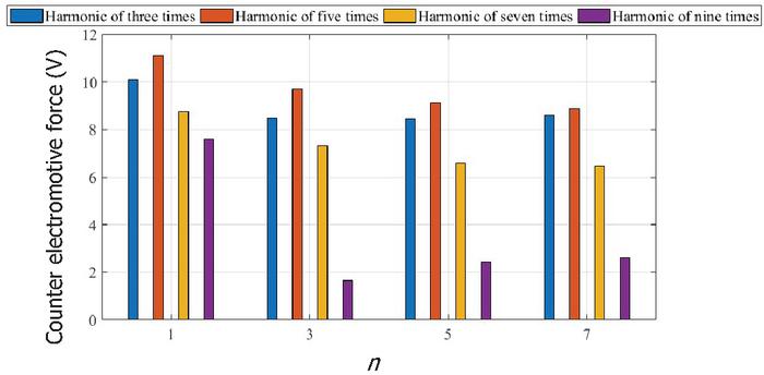
Figure 13 Harmonic bar diagram of no-load back electromotive force.
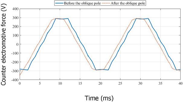
Figure 14 No-load back electromotive force before and after inclined pole.
It can be seen that when , the tooth torque is small and the high-order harmonic of no-load back electromotive force is small. When , the harmonic reduction of space-time loaded back electromotive force is no longer significant. Therefore, when the number of segments of the rotor oblique pole is , the machine performance and processing complexity are the most reasonable. At this time, the changes of tooth torque and no-load back electromotive force before and after the oblique pole are compared, as shown in Figure 14.
It can be seen that the bevel of rotor can effectively reduce the harmonic wave of tooth torque and no-load reverse electromotive force in no-load condition. In practical application, considering the convenience of mass production and processing, fewer segments are often selected for the rotor inclined pole.
3.2 The Thickness of the Magnetic Barrier
The thickness of the magnetic barrier affects the amount of permanent magnet. The thicker the magnetic barrier is, the more the amount of permanent magnet material is, the higher the output torque is [14]. In order to make rational use of permanent magnet materials, the influence of magnetic barrier thickness on load torque and efficiency is analyzed below, as shown in Figure 15.
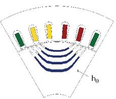
Figure 15 Schematic diagram of magnetic barrier thickness.

Figure 16 Efficiency changes with the thickness of the magnetic barrier.
The change of is increased from 1 mm to 4.5 mm at an interval of 0.5 mm, and the changes of load torque, torque ripple and efficiency are shown in Figure 16. It shows that when the thickness of magnetic barrier mm, the efficiency is high. When mm, the increase in efficiency is no longer significant, and material waste will be caused. The thickness of the magnetic barrier mm was selected comprehensively. AMBPMSG efficiency can be further improved by optimizing the magnetic barrier thickness. The research results show that the load torque and efficiency are the highest when the magnetic barrier thickness is mm, that is, the amount of permanent magnet materials can be reduced to a certain extent when the same power is output.
4 Software Common Platform
To design the structure of a new type of machine or to analyze its characteristics, it is necessary to write an electromagnetic calculation program to calculate the electromagnetic characteristics, and then analyze the characteristics of the machine according to the electromagnetic calculation results. For wind turbines with permanent magnet machine, the characteristic analysis of the target are racing back electromotive force waveform and harmonic, the cogging torque and harmonic etc., due to the manual electromagnetic calculation requires a lot of time, so this section in view of the wind turbine with permanent magnet machine to develop a fast electromagnetic calculation simulation platform.
The electromagnetic computing software common platform with a friendly, convenient machine interactive interface, and more than just have a MATLAB2017b and version of the computer operation can be realized, for complex simulation and parameter calculation can be invoked in the background, do not appear on the visual interface, so the software can supply electrical designers use to magneto electromagnetic calculation, the result can be used for reference on the practical application.
The general platform for performance simulation of permanent magnet machine requires the following functions to be realized [18]:
(1) Strong versatility. The user is allowed to input different technical parameters and structural parameters of the permanent magnet machine, so as to calculate the electromagnetic characteristics of different structural parameters.
(2) Strong intuitiveness. After the user clicks to start the calculation, the electromagnetic calculation results can be obtained directly in the window of the visual interface.
(3) Easy to reduce. Users are allowed to input parameters according to the actual situation and modify, add and delete the parameters to ensure the correctness of the input parameters.
(4) Portability. This software emulates the general platform which does not depend on the hardware equipment of the feature and does not need to be backed up in the registry. Users only need to install MATLAB2017b or above version on the PC side to ensure the universality of the program.
The interface of the general software platform for electromagnetic calculation of permanent magnet machine is shown from Figures 17 to 20.

Figure 17 Launch the welcome screen.
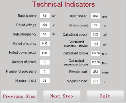
Figure 18 Technical index input interface.
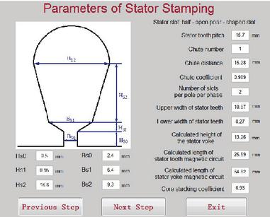
Figure 19 Stator punching parameters input interface.
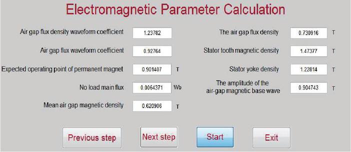
Figure 20 Electromagnetic parameter calculation input interface.
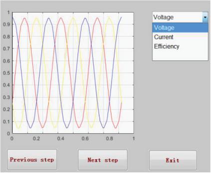
Figure 21 Counter back electromotive force waveform interface.
5 Conclusion
In this paper, starting from the shortcomings of wind turbines with permanent magnet machine, this paper introduces a kind of auxiliary magnetic barrier, permanent magnet generator based on magnetic circuit calculation method to determine electromagnetic design, finite element simulation software to establish the two-dimensional model of AMBPMSG, comparative study on the torque ripple, efficiency, the cogging torque and back electromotive force, and the AMBPMSG rotor structure optimization design. The research results show that:
(1) Compared with built-in permanent magnet wind turbines, AMBPMSG maintains high efficiency while reducing the use of permanent magnet materials, and greatly reduces the occurrence of high temperature demagnetization of permanent magnet materials.
(2) The piecewise inclined pole of the rotor can reduce AMBPMSG inverse back electromotive force harmonic content and slot torque effective value. The research results show that the effect is the best when the number of segments , thus improving the stability of no-load operation and the utilization ratio of permanent magnet materials.
(3) By optimizing the magnetic barrier thickness , AMBPMSG load torque and efficiency can be further improved. The research results show that when the magnetic barrier thickness mm, the torque ripple is the lowest, the efficiency is higher, and the stability of machine operation is improved, which has certain reference value for engineering application.
(4) Finally, according to the operation characteristics and technical requirements of the permanent magnet machine used in wind turbines and the M file of the electromagnetic calculation program, a general electromagnetic calculation platform was developed by using MATLAB software, which realized the fast and convenient electromagnetic calculation of the permanent magnet machine and avoided the tedious manual calculation process.
Acknowledgement
This project is financially supported Liaoning Provincial Department of education scientific research project (JL-1907, LJKZ1085), Liaoning Natural Science Foundation (2020-MS-240), Innovative talents in Liaoning (Special machine and its control), Shenyang young and middle-aged scientific and technological innovation talents (RC200192) and Liaoning million Talents Project. Thanking for the valuable suggestions from comrades.
References
[1] L. I. Yituo, L. U. Haifeng, Q. U. Wenlong (2019). Permanent magnet synchronous motor. S13–S13.
[2] A. A. S. Bukhari, B. P. Alalibo, W. Cao (2019). Switched reluctance motor design for electric vehicles based on harmonics and back EMF analysis. The Journal of Engineering, 17, 4220–4232.
[3] C. Wang, X. Bao, S. Xu. (2017). Analysis of vibration and noise for different skewed slot-type squirrel-cage induction motors. IEEE Transactions on Magnetics, 53(11), 1–6.
[4] Lin Ye, Cihang Zhang, Yong Tang, Wuzhi Zhong, Yongning Zhao, Peng Lu, Bingxu Zhai, Haibo Lan, Zhi Li. Hierarchical Model Predictive Control Strategy Based on Dynamic Active Power Dispatch for Wind Power Cluster Integration. IEEE Transactions on Power Systems, 2019, 34(6): 4617–4629.
[5] S. Abedi, M. He and D. Obadina. Congestion Risk-Aware Unit Commitment With Significant Wind Power Generation. IEEE Transactions on Power Systems, 2018, 33(6): 6861–6869
[6] P.J. dos Santos Neto, A. Cecílio Pinto, D. S. B. Tárcio André and E. Ruppert Filho. A Proposal to Control Active and Reactive Power in Distributed Generation Systems Using Small Wind Turbines. IEEE Latin America Transactions, 2020, 18(10): 1699–1706.
[7] X. Chen, J. Lin, F. Liu and Y. Song. Optimal Control of AGC Systems Considering Non-Gaussian Wind Power Uncertainty. IEEE Transactions on Power Systems, 2019 34(4): 2730–2743.
[8] A. Haddadi, I. Kocar, U. Karaagac, H. Gras and E. Farantatos. Impact of Wind Generation on Power Swing Protection. IEEE Transactions on Power Delivery. 2019, 34(3): 1118–1128.
[9] H. Liu, F. Bu, W. Huang, H. Xu, M. Degano and C. Gerada. Control-Winding Direct Power Control Strategy for Five-Phase Dual-Stator Winding Induction Generator DC Generating System. IEEE Transactions on Transportation Electrification, 2020, 6(1): 73–82.
[10] S. Chakraborty, D. Watson and M. Rodgers. Automatic Generation Control Using an Energy Storage System in a Wind Park. IEEE Transactions on Power Systems, 2018, 33(1): 198–204.
[11] M. Song, C. Gao, J. Yang and H. Yan. Energy storage modeling of inverter air conditioning for output optimizing of wind generation in the electricity market. CSEE Journal of Power and Energy Systems, 2018, 4(3): 305–315.
[12] S. Ghosh, Y. J. Isbeih, R. Bhattarai, M. S. E. Moursi, E. F. El-Saadany and S. Kamalasadan. A Dynamic Coordination Control Architecture for Reactive Power Capability Enhancement of the DFIG-Based Wind Power Generation. IEEE Transactions on Power Systems, 2020, 35(4): 3051–3064.
[13] H. Cheng, R. Li, F. F. Choobineh, Q. Hu and S. Mei. Dispatchable Generation of a Novel Compressed-Air Assisted Wind Turbine and Its Operation Mechanism. IEEE Transactions on Sustainable Energy, 2018, 10(4): 2201–2210.
[14] A. Lin, Z. Bie, C. Pan and S. Liu. Fast Cumulant Method for Probabilistic Power Flow Considering the Nonlinear Relationship of Wind Power Generation. IEEE Transactions on Power Systems, 2020, 35(4): 2537–2548.
[15] Y. Liu, Z. Lin, K. Xiahou, M. Li and Q. H. Wu. On the state-dependent switched energy functions of DFIG-based wind power generation systems. CSEE Journal of Power and Energy Systems, 2020, 6(2): 318–328.
[16] Y. Li et al. Day-Ahead Coordinated Scheduling of Hydro and Wind Power Generation System Considering Uncertainties. IEEE Transactions on Industry Applications, 2019, 55(3): 2368–2377.
[17] Yuanzheng Li, Tianyang Zhao, Chang Liu, Yong Zhao, Zhiyuan Yu, Kaicheng Li, Lei Wu. Day-Ahead Coordinated Scheduling of Hydro and Wind Power Generation System Considering Uncertainties. IEEE Transactions on Industry Applications, 2019, 55(3): 2368–2377.
[18] S. P. Teixeira and C. L. T. Borges. Operation Strategies for Coordinating Battery Energy Storage with Wind Power Generation and Their Effects on System Reliability. Journal of Modern Power Systems and Clean Energy, 2021, 9(1): 190–198.
[19] H. Zhao and L. Cheng. Open-Switch Fault-Diagnostic Method for Back-to-Back Converters of a Doubly Fed Wind Power Generation System. IEEE Transactions on Power Electronics, 2018, 33(4): 3452–3461.
[20] A. Verma, R. Krishan and S. Mishra. A Novel PV Inverter Control for Maximization of Wind Power Penetration. IEEE Transactions on Industry Applications, 2018, 5(6): 6364–6373.
[21] R. I. Putri, M. Pujiantara, A. Priyadi (2015). Maximum power extraction improvement using sensorless controller based on adaptive perturb and observe algorithm for PMSG wind turbine application. IET Electric Power Applications, 12(4), 455–462.
[22] Jianxin Shen, Shun Cai, Hao He. (2016). Analysis and design of synchronous magnetoresistive motor (6 of Continuous Load) parameter optimization of uniform distribution of magnetic barrier. Rotor Microcomputer, 49(012), 84–88.
[23] Junrui Xu. (2011). Identification of parameters of permanent magnet synchronous motor and its application in control. Harbin: Harbin University of Technology.
[24] Jie Wu, Qin Zhao, Baixing Zhuang. (2017). A method for optimizing the shape of magnetic poles by weakening the back electromotive force harmonics of permanent magnet synchronous motors. Micro Motor, 50(2), 24–27.
Biographies

Chunyu Qu was born in Jilin province of China on December 29, 1979, received his B.E.E and M.S. from the Shenyang University of Technology of China in 2003 and 2007 respectively, both are in Electrical Engineering. Since 2012, he has been an Assistant Professor with the school of electric power in Shenyang institute of engineering, Her research interests include New energy power generation technology and electric magnetic theory.

Zidi Ge, was born in Liaoning province of China in October, 1996. At present she is a graduate student of Shenyang Institute of Engineering, majoring in electrical engineering. Her main research direction is special electrical machine and its control technology.

Chuhan Yang was born in Liaoning province of China in August, 1996. At present she is a graduate student of Shenyang Institute of Engineering, majoring in electrical engineering. Her main research direction is special electrical machine and its control technology.

Xiuping Wang was born in shandong province of China on June 16, 1978, received his B.E.E received from the Shandong University of Technology of China in 2003, and received his M.S. from the Shenyang University of Technology of China in 2007. He received the Ph.D. degree from the Shenyang University of Technology of China in 2014. Since 2007, he has been an Assistant Professor with the school of electric power in Shenyang institute of engineering. His research interests include electric magnetic theory, modeling, simulation, optimized design and power converter, et al.
Distributed Generation & Alternative Energy Journal, Vol. 37_3, 501–524.
doi: 10.13052/dgaej2156-3306.3736
© 2021 River Publishers