Research on Solar Adsorption Refrigeration System
Di Jiang* and Dongya Tang
Henan Polytechnic Institute, Nanyang 473000, China
E-mail: dijiang476@163.com
*Corresponding Author
Received 15 June 2021; Accepted 13 July 2021; Publication 15 October 2021
Abstract
In order to achieve solar adsorption refrigeration, this paper studies the surface water source solar absorption refrigeration system combined with surface water source cooling and solar absorbent refrigeration techniques: the solar radiation intensity is adjusted by changing the distance between iodine tungsten lamps and solar cold tubes. The results show that the entire cycle has a range of solar radiation intensity of 400 to 1000 W/m, and the indoor ambient temperature ranges from 19 to 25C, and the humidity is maintained around 40%. The highest temperature in the solar cold tube adsorption bed is 12C; during the adsorption process, the temperature drops to about 20C; the solar cold tube is 160 kJ in one cycle of the solar cold tube, and the cooling coefficient is about 0.15. Conclusion: solar cold tubes can effectively utilize solar refrigeration, it is a refrigeration method for environmentally friendly, no greenhouse effects and ozone destruction, which has potential application value and has energy saving and environmental protection.
Keywords: Solar energy, cold tube, adsorption refrigeration, energy saving, environmental protection.
1 Introduction
With the continuous improvement of people’s living standards, air conditioning is increasingly widely used, air conditioning energy consumption accounts for about 30% of the total national energy consumption. In recent years, the supply of conventional energy is tight, and the awareness of environmental protection is constantly strengthened, so it is urgent to develop and utilize clean and sustainable energy. Solar energy is a kind of clean, renewable energy and widely distributed, inexhaustible. The application of solar energy refrigeration system has positive significance for alleviating energy shortage and protecting environment. Solar energy as an environmentally friendly renewable energy, because of its wide coverage, large reserves, renewable, no pollution and other characteristics, has become one of the most focused. In the refrigeration field, the use of solar energy includes absorption refrigeration and adsorption refrigeration two categories. Among them, solar energy adsorption refrigeration system can effectively use low-grade energy, does not produce polluting substances, in environmental protection and energy saving convenience shows a huge advantage, in today’s worsening environmental crisis has been widely favored.
Solar cooling tube has great market prospect and potential application value. Solar cooling tube can efficiently use solar radiation energy, provide cold and heat for production and life continuously, with the advantages of low cost, high efficiency, clean and pollution-free. In addition, the solar cooling tube air conditioning system and the building skillfully combined together, not only to form a visual beautiful effect, but also to achieve the purpose of energy saving, green building will become the development trend of future buildings. Solar energy adsorption refrigeration system energy saving and environmental protection, for energy saving and emission reduction has a positive significance. This system has no moving parts, no need for anti-vibration and noise reduction measures, small maintenance workload, no power consumption equipment except water pump and electric heater. It is especially suitable for areas with poor power resources and abundant solar energy resources. Solar cooling tube is a refrigeration element based on solid adsorption principle, which uses solar radiation as driving heat source and independently completes the adsorption and desorption process in a single cooling tube. With the continuous development of solar cooling tube technology, its problems are more and more prominent, mainly in the solid adsorption refrigeration vacuum degree is difficult to maintain, the adsorption bed heat collection efficiency is low.
In this paper, the solar radiation is replaced by the iodine tungsten lamp in the room and the solar radiation intensity is adjusted by changing the distance between the iodine tungsten lamp and the solar cooling tube. The research has potential application value and the characteristics of energy saving and environmental protection.
There is no small number of research on refrigeration systems. Salilih tests the performance of solar cooling systems under different operating pressures [1]. Nguyen experimentally studied the influence of variable geometry ejector (VGE) design on solar ejector refrigeration system [2]. Arazazmeh et al. studied the thermal performance of a new solar multi-effect refrigeration system [3]. Sharifi et al. took the temperature of generator and evaporator as experimental variables to improve the performance of the single-effect lithium bromide/water absorption refrigeration system [4]. Samson et al. Modeling and verification of solar adsorption refrigeration system [5]. GZ et al. used different CFD models to carry out numerical simulation on the steam ejector of solar refrigeration system, reveal its flow structure and evaluate its performance [6]. He et al. proposed a new SA-CCR system with air-cooled steam compression refrigeration (ACR) cycle [7]. Zhao et al. proposed the integration of a new solar adsorption refrigeration system with a compound parabolic concentrator (CPC) adsorber [8]. Ding et al. elaborated the working principle and working principle of the semiconductor refilled device by solar cells, and put forward the optimization scheme of the system [9], but the photovoltaic industry is still in the development stage. Elakhdar et al. studied the application of low-grade solar energy in combined jet refrigeration and organic rankine cycle refrigeration power generation [10]. Cheng Youliang et al. programmed a small single-effect lithium bromide absorption refrigeration unit (12 kW) model to study the thermal performance of the small refrigerator under design conditions and variable conditions and the operation state of the unit. The research of solar energy refrigeration technology has been carried out all the time, most of the refrigeration system is relatively complex, the refrigeration technology is still to be developed, and the economy is not high.
In this experiment, solar radiation is replaced by iodine tungsten lamp in the room, and solar radiation intensity is adjusted by changing the distance between iodine tungsten lamp and solar cooling tube. The solar cooling tube can effectively use solar energy to refrigerate, and it is an environment-friendly refrigeration method without greenhouse effect and ozone destruction potential. The research has potential application value, and it has the characteristics of energy saving and environmental protection.
2 Research Methods
2.1 Operating Principle of Solar Adsorption Refrigeration Tube
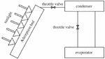
Solar adsorption refrigeration is a refrigeration cycle in which the adsorbed working medium pair completes the process of adsorption and desorption on the collector driven by solar energy as the heat source. The schematic diagram of its refrigeration system is shown in Figure 1:
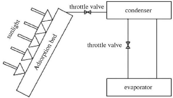
Figure 1 Typical Data Center Infrastructure [18, 19].
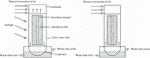
Cycle is as follows: during the day, the sun to heat of adsorption bed, in the adsorption bed adsorption bed temperature increasing, when the temperature rises to the refrigerant in the adsorption bed, under the pressure of saturated temperature, the refrigerant start from stripping out of the adsorption bed, stripping out the refrigerant vapor through condensation into the evaporator, condenser release a large amount of condensing heat; At night, the solar radiation disappears and the temperature begins to slowly drop. When the temperature of the adsorption bed reaches the saturation temperature of the refrigerant under the pressure, the adsorption process occurs, and the refrigerant evaporates in the evaporator, absorbing a large amount of latent heat of vaporization to achieve the purpose of refrigeration. Figure 2 is the schematic diagram of the cooling cycle of solar cooling control.
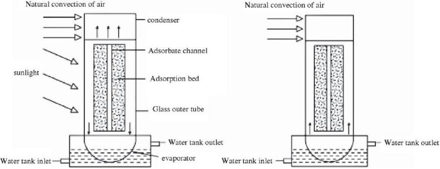
Figure 2 Schematic diagram of cooling cycle of solar cooling tube.
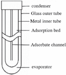
The new solar cooling tube designed in this paper is composed of adsorption bed, condensation end and evaporation end, etc. The adsorption bed is made of thin-walled stainless steel, and six equidistance rectangular ribs are arranged inside to greatly enhance the thermal conductivity of the adsorption bed. The adsorption bed is arranged in the center of the adsorption bed with an adsorbent steam channel. The condensing end of the cold pipe is also made of stainless steel, which is beneficial to improve the condensing rate. The sealing joint between condenser and glass outer tube should be sealed with “O” ring, and the interface should be coated with high vacuum adhesive. The cycle process is as follows: in the daytime, the cold tube absorbs solar radiation, the adsorption bed gradually rises, when the temperature in the adsorption bed reaches the desorption temperature of the refrigerant, the refrigerant begins to desorption from the adsorption bed, and is cooled into liquid by the condenser. The outer wall of the condenser and the outdoor heat transfer through natural convection, releasing a large amount of condensation heat. When the sun goes down, the cold tube no longer receives solar radiation, and the temperature of the adsorption bed begins to decrease. When the temperature in the tube reaches the refrigerant adsorption temperature, the refrigerant in the evaporator is refrigerated by phase change. Its structure is shown in Figure 3:
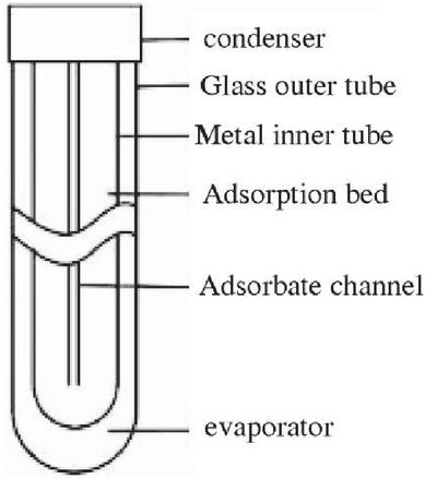
Figure 3 Composition diagram of Solar cooling pipe.
Table 1 Structural parameters of the new solar cooling pipe
| Cold Pipe Structure Parameters | Numerical (mm) |
| The casing diameter | 58 |
| Adsorption/collector outer diameter | 48 |
| Condensation end/evaporation end length | 250 |
| Fin width | 14 |
| Thickness of glass tube wall | 1.5 |
| Adsorption bed length | 1200 |
| Glass tube length | 1800 |
| External diameter of adsorbate channel | 16 |
| The length of the fin | 1200 |
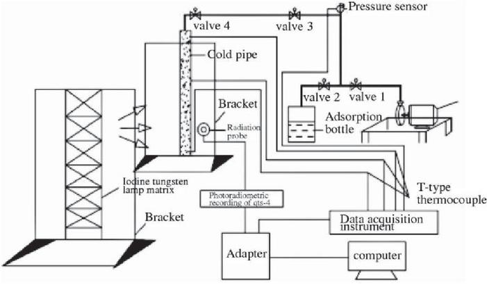
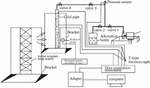
Figure 4 Solar cooling tube cooling performance test platform.
2.2 Cold Control Cold Performance Test System
Figure 4 shows the solar cooling performance test system. The experimental system consists of the following three parts: radiation intensity test part, indoor parameter test part and the solar cooling tube parameter test part. The radiation intensity testing part includes TBQ-2 general radiation meter, QTS-4 optical radiation recorder and digital conversion device. Indoor parameter test by temperature and humidity meter to complete; the parameter test part of the solar cooling tube is composed of temperature data acquisition system, thermocouple, pressure transmitter, etc., and the above parts are connected with the computer data processing system through USB port. The thermocouple is arranged in the refrigerant channel, the outer wall of the condensation end, and the outer wall of the evaporation end, and the temperature of the adsorption bed, condenser and evaporator is approximately measured. The agilent data processing system is programmed to record values every 2 min and measure refrigerant desorption every 30 min using a marker method. A complete refrigeration cycle is 24 h.
The experiment was carried out in the laboratory, starting at 8:00 in the morning and ending at 8:00 the next day. The experiment was a cycle. The basic principles of this experimental study are summarized as follows: before the start of the experiment, open the iodine tungsten lamp (simulated solar radiation and solar radiometer instantaneous record the sun radiation and total amount) for solar cooling tube heated (by adjusting the distance between tungsten matrix and cold tube to change iodine tungsten lamp radiation intensity), adsorption bed temperatures began to rise slowly, when the temperature reaches stripping temperature of the refrigerant. The refrigerant starts to get rid of the restriction of the adsorbent, desorbs out of the adsorption bed in the form of steam, and then enters the condensing end through the adsorbent channel for heat exchange with the indoor air. Finally, the cooled refrigerant liquid flows into the evaporator under the action of gravity. During the adsorption phase, the iodine tungsten lamp is turned off. At this point, the temperature in the adsorption bed begins to fall slowly, and when the temperature drops to the saturation temperature under the evaporation pressure, the adsorption process occurs, and the refrigerant produces a large amount of cooling due to evaporation.
3 Results Analysis and Discussion
3.1 Power Consumption in Data Centers
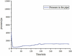
Vacuum process: first close valve 1 and valve 2, start the vacuum pump, then open valve 1 and valve 3, and continue to work on the solar cooling pipe for 40 min. The iodine tungsten lamp matrix is then turned on to heat the cold tube and continue vacuuming the system. As the volume of the solar cooling tube is very small, the system pressure drops rapidly from atmospheric pressure to about 500 Pa within 10 min. As the vacuuming process continues, the vacuum degree in the solar cooling tube eventually stabilizes at about 400 Pa, reaching the ultimate pressure value at this state point. After the vacuum process lasts for 40 min, the iodine tungsten lamp is turned on and the solar cooling tube is heated.
The pressure in the cold tube does not fluctuate obviously in the initial stage of the thermal emptying process, because the temperature of the adsorption bed does not reach the desorption temperature of the refrigerant in this state. As the temperature of the adsorption bed continues to increase, when the temperature reaches the desorption temperature, the refrigerant is free from bondage, and the desorption water vapor makes the pressure in the cold tube continue to increase. After about 3 hours, the pressure in the system rises to about 1300 Pa and remains stable, and the refrigerant is completely desorbed.
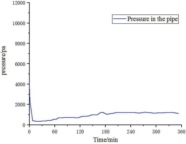
Figure 5 Pressure change in the cold tube during vacuum pumping.
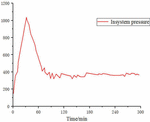
3.2 Refrigerant Filling Process
In the process of refrigerant filling, the pressure change curve in the system is shown in Figure 6. When the vacuum in the adsorption bottle is completed, close the vacuum valve 1, open the vacuum valve 3, so that the solar cooling pipe and the adsorption bottle are connected. At this point, the pressure in the system rapidly rises to about 1200 Pa. When the vacuum valve 3 is opened, the solar cooling tube is connected with the adsorption bottle. With the passage of time, the pressure in the system decreases gradually, from the initial 1200 Pa to about 500 Pa. This is because the temperature of the adsorption bed of the cold tube decreases gradually during the static adsorption and adsorption of the refrigerant in the bottle. The absorbent in the solar cooling tube continuously absorbs the water vapor in the bottle, and the pressure in the system drops. At the beginning, the pressure in the system dropped at a fast rate. As time went on, the pressure dropped at a slower and slower rate. Finally, the pressure in the system remained between 400 and 500 Pa.
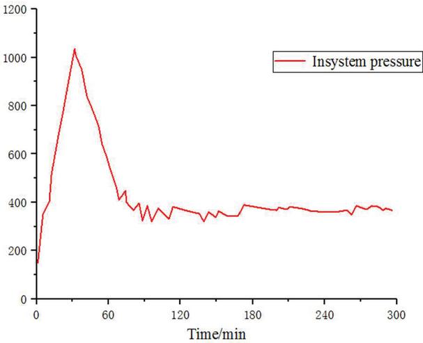
Figure 6 System pressure variation during refrigerant filling.
3.3 Change of Adsorption Bed Temperature
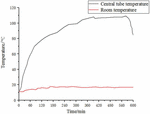
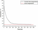
Figures 7 and 8 show the temperature variation curve of the adsorption bed during the adsorption refrigeration experiment of the solar cooling tube. At the initial stage, the temperature in the cold tube tends to the ambient temperature. When the iodine tungsten lamp is turned on, the simulated sunlight starts to heat the cold tube adsorption bed through the outer glass tube, and the temperature of the adsorption bed begins to rise gradually. When the experiment was carried out to about 180min, the desorption process occurred, and the refrigerant steam began to break free of the binding of the adsorbent, entered the condenser through the adsorbent channel, and then was condensed into liquid and flowed into the evaporator along the inner wall.
Table 2 The temperature of the central tube in the adsorption desorption section varies with time
| Adsorption Bed | The Central Temperature | |
| Phase | Final Temperature/C | Changes Greatly in Time/Min |
| Stripping section | 120 | 240 |
| Adsorption stage | 30 | 180 |
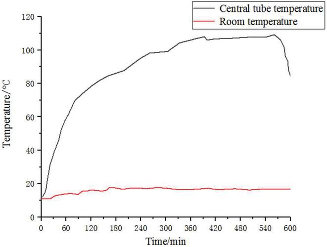
Figure 7 Changes of adsorption bed and ambient temperature in desorption section.
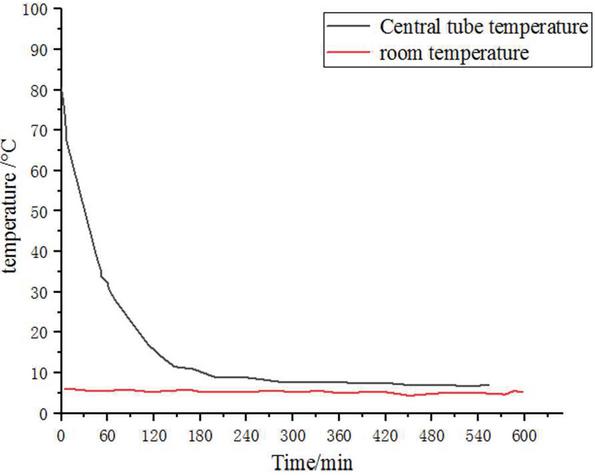
Figure 8 Changes of adsorption bed and ambient temperature in the adsorption section.
In the initial stage, the temperature rise rate in the adsorption bed is large because of the big temperature difference between the sunny and shady surfaces. With the progress of the experiment, the temperature of the adsorption bed gradually rises and finally approaches 120C. At this stage, because the temperature difference in the adsorption bed gradually shrinks, the heat conduction in the adsorption bed slows down, and the temperature rise rate in the adsorption bed gradually slows down and tends to be stable. When the experiment goes on for about 500 min, the iodine tungsten lamp matrix is closed. At this time, the solar cooling tube no longer receives the radiation from the iodine tungsten lamp, and the temperature in the adsorption bed begins to decrease slowly. At this time, the desorption process is still continuing. The desorption process was completed after about 600min of the experiment. Then the solar cooling tube continues to exchange heat with the outside world through the wall of the tube, and the temperature of the adsorption bed continues to drop. When the temperature reaches the adsorption temperature of the adsorbent (about 30C), the adsorption process occurs, and the refrigerant begins to change phase in the evaporator, taking away a lot of latent heat of vaporization.
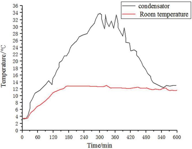
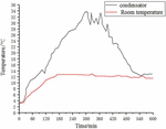
Figure 9 Condensation temperature and room temperature.

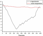
Figure 10 Evaporation temperature and room temperature.
3.4 Condensation Temperature and Evaporation Temperature Change
Figure 9 shows the variation curve of the ambient temperature on the sunny side of the solar cooling tube with the radiation intensity of the simulated light source. The maximum temperature is about 34C. When the iodine tungsten lamp is turned on, the solar cooling tube is radiated by the simulated light source. The refrigerant breaks free of the adsorbent and enters the condenser through the adsorbent channel. The refrigerant steam exchanges heat through the outer wall of the condenser and the indoor air, releasing condensation heat. In the condensation process, the maximum temperature of the condenser can reach 34C and the minimum temperature is 21C. The maximum temperature difference between the condensation temperature of the cold tube and the ambient temperature on the sunny side is about 14C.
Figure 10 shows the change of evaporation temperature in a refrigeration cycle; when the iodine tungsten lamp matrix is closed, the cold tube stops receiving the radiation from the analog light source, the temperature of the adsorption bed begins to decrease gradually, and the pressure also decreases accordingly. When the pressure in the evaporator reaches the saturation pressure value corresponding to the evaporation temperature of the refrigerant liquid, the refrigerant begins to adsorb. Because there is no cooling water into the center tube, the cooling unit tube adopts natural convection cooling mode. Initially, the refrigerant liquid is at a higher temperature, and a portion of the latent heat of vaporization of the refrigerant is needed to achieve the desired cooling temperature. Then the evaporation temperature decreased rapidly and reached the lowest value of 8C at the time of 240 min. In the initial stage of the experiment, the adsorption capacity of the adsorption bed is strong, the evaporation rate is fast, and the evaporation temperature decreases sharply. When the adsorption capacity of the adsorption bed tends to saturate, the evaporation temperature begins to rise gradually, and gradually approaches the ambient temperature.
4 Conclusions
(1) Refrigeration performance experiment of solar cooling tube solar radiation intensity range of 4001000 W/m throughout the experiment cycle, indoor ambient temperature range of 1925C, humidity maintained at about 40%; the ultimate pressure in the solar cooling tube can reach about 300 Pa.
(2) The maximum temperature in the desorption process of the solar cooling tube adsorption bed is 120C, which can be fully desorbed; in the process of adsorption, the temperature drops to about 20C, which can fully meet the requirements of adsorption. In the process of experiment, the maximum condensation temperature can reach 34C, the maximum temperature difference of condensation temperature is about 15C, and the minimum evaporation temperature is 8C. The refrigeration capacity of a single cold tube is 160 kJ, the refrigeration coefficient is about 0.15, and the refrigeration time can last for more than 10 hours.
References
[1] Boushaba, H., Mimet, A., Ganaoui, M. E., Mouradi, A. Performance evaluation of an adsorption refrigeration system powered by solar heat storage based on Moroccan irradiation[J]. MATEC Web of Conferences, 307(3), p. 01014, 2020.
[2] Youssef, P. G., Mahmoud, S. M., Al-Dadah, R. K. Performance analysis of four bed adsorption water desalination/refrigeration system, comparison of AQSOA-Z02 to silica-gel[J]. Desalination, 375, pp. 100–107, 2015.
[3] Shi, C., Chen, H., Chen, W., Zhang, S., Chong, D., Yan, J. 1D model to predict ejector performance at critical and sub-critical operation in the refrigeration system[J]. Energy Procedia, 75, pp. 1477–1483, 2015.
[4] Yatagan Baba, A., Kilicarslan, A., Kurtbas, I. Exergy analysis of R1234yf and R1234ze as R134a replacements in a two evaporator vapour compression refrigeration system[J]. International Journal of Refrigeration, 60, pp. 26–37, 2015.
[5] Kocyigit, N. Fault and sensor error diagnostic strategies for a vapor compression refrigeration system by using fuzzy inference systems and artificial neural network[J]. International Journal of Refrigeration, 50, pp. 69–79, 2015.
[6] She, X., Yin, Y., Zhang, X. Suggested solution concentration for an energy-efficient refrigeration system combined with condensation heat-driven liquid desiccant cycle[J]. Renewable Energy, 83, pp. 553–564, 2015.
[7] Smolka, J., Palacz, M., Bodys, J., Banasiak, K., Fic, A., Bulinski, Z., Nowak, A. J., Hafner, A. Performance comparison of fixed- and controllable-geometry ejectors in a CO2 refrigeration system[J]. International Journal of Refrigeration, 65, pp. 172–182, 2016.
[8] Agrawal, T., Varun, Kumar A. Solar absorption refrigeration system for air-conditioning of a classroom building in Northern India[J]. Journal of the Institution of Engineers, 96(4), pp. 389-396, 2015.
[9] Agrawal, T., Varun, Kumar A. Solar absorption refrigeration system for air-conditioning of a classroom building in Northern India[J]. Journal of the Institution of Engineers, 96(4), pp. 389–396, 2015.
[10] Nunes, T. K., Vargas, J. V. C., Ordonez, J. C., Shah, D., Martinho, L. C. S. Modeling, simulation and optimization of a vapor compression refrigeration system dynamic and steady state response[J]. Applied Energy, 158(NOV.15), pp. 540–555, 2015.
Biographies

Di Jiang graduated from Southeast University with a bachelor’s degree in thermal and power engineering in 2004 and a master’s degree in electrical engineering from Huazhong University of science and technology in 2013. He has been working in Henan Polytechnic Institute since 2006 and has rich experience in teaching and scientific research of HVAC and building electrical equipment.

Dongya Tang graduated from Southwest Petroleum University with a bachelor’s degree in building environment and equipment engineering in 2008 and a master’s degree in heating, gas supply, ventilation and air conditioning engineering in Southwest Petroleum University in 2012. Since 2013, he has worked in Henan Polytechnic Institute, mainly engaged in research and teaching of HVAC and building equipment.
Distributed Generation & Alternative Energy Journal, Vol. 37_2, 129–144.
doi: 10.13052/dgaej2156-3306.3721
© 2021 River Publishers