Active Power Filters in Aircraft Electric Power Systems: A Comparison Among Conventional and Advanced Compensation Techniques
Saifullah Khalid1,*, Sonia2, Narendra Pratap Singh1 and Khadim Moin Siddiqui3
1Airports Authority of India, Lucknow, India
2IIM, Lucknow, India
3SRMCEM, Lucknow, India
E-mail: saifullahkhalid@Outlook.com; sonia@iim.ac.in; naren.p.singh@gmail.com; siddiquikhadim@srmcem.ac.in
*Corresponding Author
Received 28 September 2021; Accepted 24 October 2021; Publication 22 April 2022
Abstract
The world is moving towards more electric aircraft due to its benefits for more efficiency and less dependence on conventional energy. However, as conventional energy has its drawback of reduced total energy efficiency for aircraft, the use of more electronics is accountable for higher losses, unbalance currents, reduced power supply performance, and generation of harmonics. In this paper, a comparison among three conventional control techniques (Synchronous Rotating Frame, Sinusoidal Current Control and Constant Instantaneous Power Control) and advanced control techniques (ANN, fuzzy logic controller, genetic algorithm, adaptive blanket body cover algorithm, the combination of ANN & fuzzy logic controller and ANN with the application of genetic & adaptive blanket body search algorithm) for aircraft shunt active power filter has been proposed. Furthermore, the best control schemes for aircraft active power filters will be proposed to depend upon the THD of source current and voltage and the compensation time (speed).
Keywords: Aircraft electric power systems, aircraft active power filter, ANN, fuzzy logic control, adaptive blanket body search algorithm, genetic algorithm, more electric aircraft.
1 Introduction
The world is slowly moving to remove the bar of dependency on the oil industry to meet its energy demand and so the aerospace industry. The more electric aircraft is one step towards this. Hopefully, shortly one can see the all-electric aircraft [1–3]. It starts initially with a greater application of power electronics in the aircraft. Recent power electronics researches have led us toward power generation and conversion, actuators, and other control systems to be used in the flight. However, everything good also comes with some limitations [4]. The result is harmonics, unbalanced current, higher losses, and reduced performance of aircraft systems [1, 5]. The one solution for all the discussed problems is the aircraft active power filter. There are many control techniques, i.e., “conventional (Constant Instantaneous Power Control (CIPC), Sinusoidal Current Control (SCC), and Synchronous Rotating Frame (SRF)) and Artificial intelligence-based advanced control schemes like ANN, Fuzzy logic control (FLC), Genetic algorithm (GA), PSO, Bee algorithm (BA), adaptive blanket body search algorithm (ABBC), adaptive mosquito blood search algorithm (AMBS), adaptive spider net search algorithm (ASNS), adaptive neuro-fuzzy interference system (ANFIS) and many more” [6–14].
The purpose of aircraft active filters is finally similar. “The primary goal is to compensate for current harmonics in the aircraft system. A variety of active filters also extend upon this initial goal to include reactive power compensation and as an outcome of this power quality improvement. In real-time, their controllers decide the compensating current reference and compel a power converter to create it accurately. In this way, the active filtering can be discriminating and adaptive. A shunt active filter can compensate only for the harmonic current of a selected non-linear load. It can unremittingly trail alters in harmonic content. This active filter model subtly compensates for current harmonics and reduces the total harmonic distortion” [15, 16].
In this paper, the model of the system using three loads has been presented. “Three different loads have been connected to the aircraft system. The set of the load consists of a three-phase rectifier parallel with the inductive load and an unbalanced load connected a phase with the midpoint; the three-phase rectifier connects a pure resistance directly, three-phase inductive load linked with the ground point and combined all three loads connected with the system together at a different time interval to study of the effectiveness of the control schemes verify the functionality of the active filter in its ability to compensate for current harmonics” [6]. Most of the circuit parameters used have been taken from [5]. “The simulation will be done for 15 cycles, and results will be analyzed based on the THD of current and voltage” [17, 18].
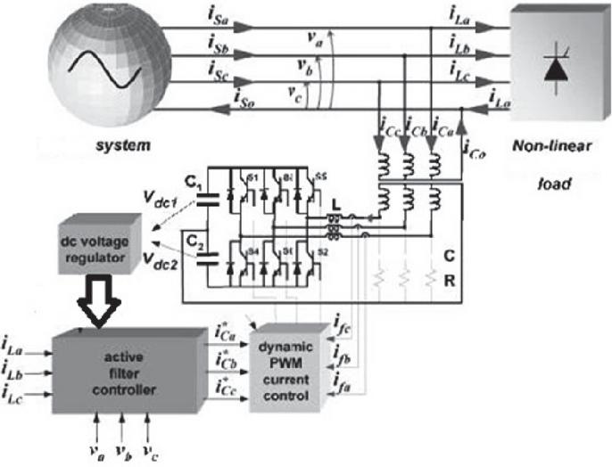
Figure 1 Model of the shunt active power filter for 400 Hz aircraft system.
2 Aircraft Active Power Filter
Figure 1 shows the model of the filter for an aircraft power system. “A shunt active filter is believed a current source because it injects non-sinusoidal current through the parallel branch of the network to compensate for the current harmonic requirement of the non-linear load. The active filter controller’s function is to sense and examine the load current and determine the correct reference harmonic current for the inverter. Once the correct reference harmonic content is decided, this reference current is fed through an appropriate current controller, sent to the inverter for injection into the network [1, 5].
There are some troubles related to the dc capacitor voltages to works out in the split-capacitor converter topology. This converter topology permits currents to flow through one of the dc capacitors (C or C) and to return to the ac neural wire, causing voltage deviation between the dc capacitors. Once this voltage deviation is controlled, the split-capacitor converter topology can become an attractive solution to be generally applied in aircraft systems since it uses an (n - l)-leg PWM converter. For example, a 2-leg converter could be used in a three-phase system, where two phases are connected to the converter legs and the third one is connected to the midpoint of the dc bus [7, 16]. Current control is employed through feedback modulation of a dynamic hysteresis band PWM controller. The shunt line current trails the reference current within a hysteresis band. By comparing the reference currents computed by the controller with the measured values of compensation currents” [15, 19].
3 Compensation Techniques
An algorithm must be developed based on a power theory that can construe the measured data to produce a reference signal to control a switching compensator.
3.1 Conventional Compensation Techniques
This section will present the three techniques, i.e., CIPC, SCC, and SRF, to develop the reference signal generating algorithms.
3.1.1 Aircraft constant instantaneous power control (ACIPC) strategy
CIPC is the most popular conventional technique for compensation using the active filter. With a little alteration in the 50/60 Hz applicable CIPC strategy, it can also be used in a 400 Hz aircraft system. To function CIPC well in an aircraft system, the LPFs need to be 6.4 KHz, shown in Figure 2. The model’s further processing is the same as in the 50/60 Hz supply system [15, 16].
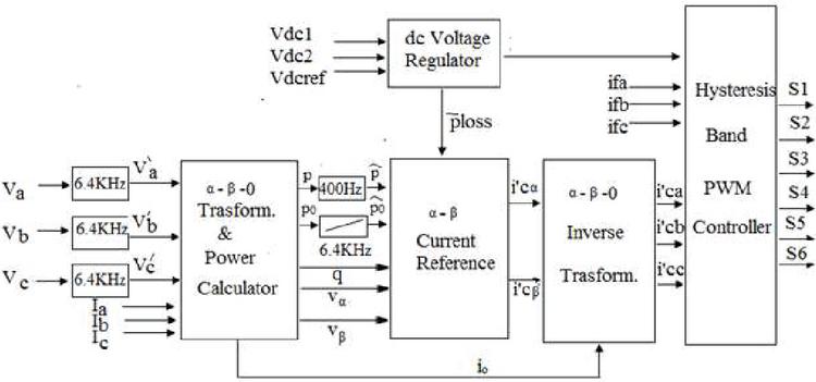
Figure 2 Control of aircraft active power filter (AAPF) using aircraft constant instantaneous power control (ACIPC) strategy.
3.1.2 Aircraft sinusoidal current control (ASCC) strategy
It is well known that the ACIPC strategy does not perform very well in case of unbalanced conditions. Therefore, a new strategy named an ASCC strategy has been developed with some ACIPC strategy changes to overcome this issue. “The modification includes a positive sequence detector shown in Figure 3, which replaced the 6.4 kHz cut-off frequency low-pass filters and correctly finds the phase angle and frequency of the fundamental positive sequence voltage component and shunt active power filter compensates the reactive power of the load. The further processing of the model is of same as in the ACIPC technique discussed above” [9, 20].
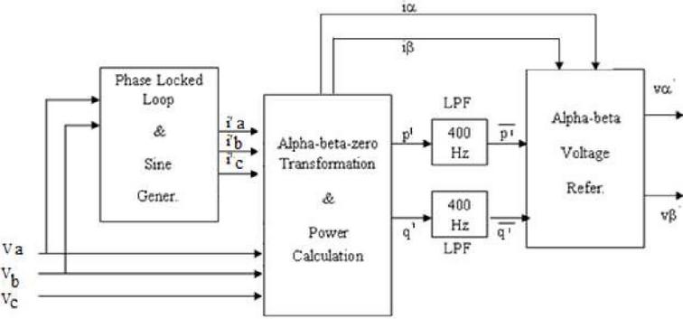
Figure 3 Fundamental positive-sequence voltage detector for aircraft sinusoidal current control (ASCC) strategy.
3.1.3 Aircraft synchronous rotating frame (ASRF) strategy
Synchronous Rotating Frame (SRF) Strategy is based on Park transformations. After the transformation into direct, quadrature, and zero-sequence components, it can be analyzed very simply. The details of the functioning of the techniques can be found in [17].
Little alterations in the model’s functioning shown in Figure 4 are also required in this technique to perform well in the aircraft system. “For this reason, the zero-sequence component of current has not been considered. So, the zero-sequence subtract block takes away the zero-sequence current from the current and output current and comprises only positive sequence and negative sequence components. After its park transformation, the output current in the d-q frame is composed of only instantaneous active and reactive current. A low-pass filter attains the division of the dc and ac components of the active current for compensation of the harmonic and reactive current. This active current passes through a low pass filter. The signal came from the dc voltage regulator. Finally, a Park counter-transformation subtracting from the load currents generates the reference current” [21].
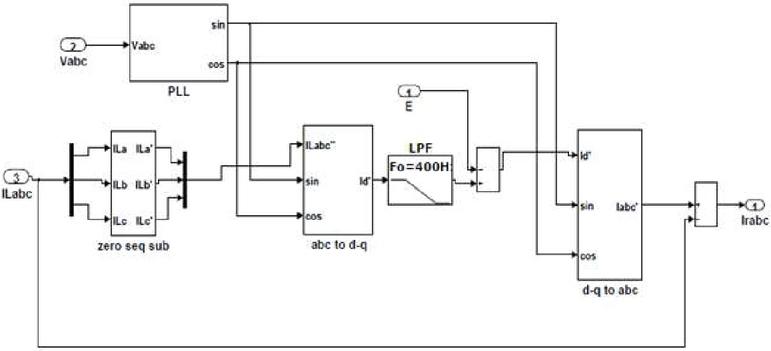
Figure 4 Simulink model of the aircraft active power filter (AAPF) using aircraft synchronous reference frame (ASRF) strategy.
3.2 Advanced Compensation Techniques
In this section, different advanced controllers/Algorithms have been discussed that may be used to optimize the conventional control strategies. For example, ANN controller, Fuzzy logic controller, Genetic algorithm, Adaptive blanket body search algorithm, and a combination of these have been used to check these strategies’ improved performances.
3.2.1 Aircraft active power filter using artificial neural network (ANN) controller
In this paper, an ANN comprises two hidden layers with ten neurons each. In addition, one output layer with three neurons has been applied to CIPC, SCC, and SRF strategies, respectively [11, 12, 22]. “The logarithmic activation function is the base of the two hidden layers of neurons. The linear activation function is n for the output layer neurons” [23]. Figure 5 presents the model of the ANN controller.
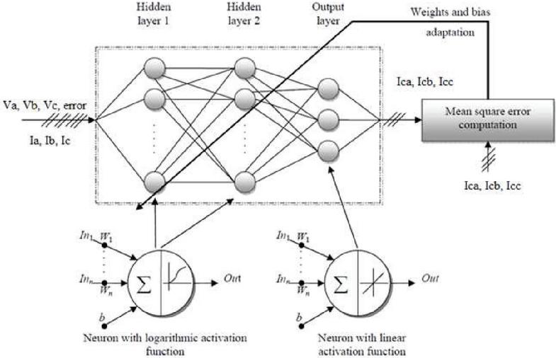
Figure 5 ANN for modeling.
“The ANN has seven inputs (v, v, v, dc voltage error, i, i, i) and three outputs (i, i, i) as observed in the different strategies. The adaptation of the weights (W) and bias (b) in the ANN is based, first, on the computation of the mean square error (MSE) between the outputs of the PQ technique and those of the ANN, and secondly, on the execution of ‘Levenberg-Marquardt backpropagation’ algorithm” [17, 23].
3.3 Aircraft active power filter using fuzzy logic controller
“The steps involved in designing a controller using fuzzy logic require a certain set of information, which is explained in subsequent sections. Once the design problem is identified, the algorithm is simple, i.e., the input and output variables required and the desired kind of output” [24].
The fuzzy logic consists of the following four main parts. First, a few sets of information/rules must be made based on the complexity and performance requirements. The more the number of rules, the more the delay, but the output may be more accurate [10, 18, 25]. Considering the balance between the number of rules and output, a set of rules has been defined, as shown in Table 1.
• Fuzzifier (Transformation 1)
• Knowledge Base
• The inference engine is the heart of FLC
• Defuzzifier (Transformation 2)
Table 1 Fuzzy rules [24]
| Error | Negative | Zero | Positive |
| Negative | Big Negative | Positive | Big Positive |
| Zero | Big Negative | Zero | Big Positive |
| Positive | Big Negative | Negative | Big Positive |
3.3.1 Aircraft active power filter using genetic algorithm
“A genetic algorithm (GA) is a search technique used in computing to find an optimal solution for a search problem. Commonly, the algorithm terminates if a maximum number of generations has been produced or a satisfactory fitness level has been reached for the population” [23, 25–28].
In this paper, the inductor filter’s optimum value (L) has been calculated using a Genetic Algorithm. It has been done offline using a small program written in MATLAB with defined limits, inequality, and bounds. Some of the data has been used from the previous ANN model. The optimized value is 0.187 mH as compare to the previous of 0.25 mH.
3.3.2 Aircraft active power filter using adaptive blanket body cover algorithm (ABBC)
The novel ABBC Algorithm was proposed by Khalid S. in 2017 [8]. This algorithm functions efficiently as a search method for non-linear continuous optimization issues.
Humans’ basic nature inspires this algorithm’s concept for using the blanket to cover the body during chilled winter. “The blanket has been initially folded to cover the upper body. When the body senses the cold in the lower portion, the upper fold will be opened. After that, the lower portion of the blanket will be folded to cover the body. Only the lower or upper portion fold alone cannot cover the whole body when the full body senses the cold. So, the full blanket will be folded such that the layer of the blanket will be doubled” [8, 29].
This paper has applied this algorithm to search the optimum values for Kp and Ki used in the PI controller of the voltage control loop of AAPF.
“The objective function (OB) is determined to give their optimum value with the conditions of % overshoot, rise time, and settling time. Thus, the objective function has an equation that has three variables, i.e., % overshoot, rise time, and settling time. Initially, the Boundary of Kp and Ki, their higher limits and lower limits, then radius value, ABBC backtracking conditions, objective function, and stop criteria have been outlined” [29].
Figure 6 presents the flow chart used to search the optimum values using the ABBC algorithm. “The values initially used for Kp and Ki were 0.1 and 45, respectively. After the application of this algorithm, the new calculated values are 0.184 and 14.32. It has been ascertained that whereas using these ABBC calculated values of Kp and Ki, the THD of supply current and voltage are reduced staggeringly, proving that the values are optimum” [29].
The effectiveness of this algorithm is proved by the great results and less computational time. “There has been a counter used, which will count the number of iterations. Therefore the program will stop once the count is up to forty, i.e., the stopping criteria are forty iterations” [8].
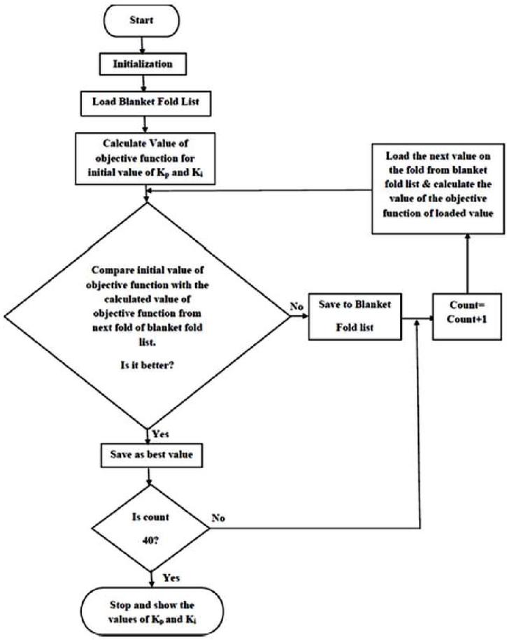
Figure 6 Flow chart for finding the parameters using ABBC.
3.3.3 Aircraft active power filter using combination of artificial intelligent techniques
In this section, combinations of different advanced techniques discussed before have been simulated for the aircraft power utility. Two combinations have been taken. In the first combination, ANN and FLC have been applied to the system. They have been simulated to estimate the system’s performance. In the second combination, ABBC, GA, and ANN control have been considered to evaluate the optimized performance of the AAPF.
3.3.4 AAPF using ANN & fuzzy logic controller
As discussed earlier that ANN has been applied to the current control section. In contrast, FLC has been associated to the voltage control section of the filter. The same has been applied in this section. The difference is that they have been applied together to optimize the system together.
3.3.5 Aircraft active power filter using ANN with application of genetic & adaptive blanket body search algorithm
As discussed earlier, the ABBC algorithm has been applied to discover the Kp and KI values of the controller used in the voltage control loop. GA has been employed to find out the optimum value of the filter inductor and, ANN has been applied to the current control section. The same has been applied in this section. The difference is that they have been applied together to optimize the system together.
4 Comparisons Using Simulation Results
In this section, the comparisons have been made based on the THD calculated by Matlab. Initially, the simulation results of the aircraft system without any filter, i.e., the uncompensated system, have been discussed. Later on, the comparisons were made based on the simulation results for conventional and advanced control schemes.
4.1 Uncompensated System
“The set of loads for the aircraft system consist of three loads. The first load is a three-phase rectifier parallel with the inductive load and an unbalanced load connected in a phase with a midpoint (Load 1). The second one is a three-phase rectifier that connects a pure resistance directly (Load 2). The third one is a three-phase inductive load linked with the ground point (Load 3). A combination of all three loads connected with the system together at different time intervals to study the effectiveness of the control schemes has been used to verify the active filter’s functionality in its ability to compensate for current harmonics. For all three loads connected, Load 1 is always connected, Load 2 is initially connected and is disconnected after every 2.5 cycles, Load 3 is connected and disconnected after every half cycle. All the simulations have been done for 15 cycles” [29]. Figure 7 shows the MATLAB/SIMULINK model for load 1, 2, and 3 connected in the circuit. Load 1 is always connected. Load 2 is initially connected and disconnects after every 2.5 cycles. Load 3 connects to the aircraft supply system after every half cycle.
The THD of source current and source voltage was 9.5 percent and 1.55 percent, respectively, according to the simulation findings given in Figure 7, which is outside the stated limit of international standards [30–36].
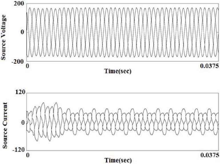
Figure 7 Waveforms of source voltage and current with three loads.
4.2 Compensated System
In this section, three different loads connected with the aircraft system will be simulated alone and together at different time intervals. THD of current and voltage will be calculated. In the following sections, compensated systems using conventional and advanced control techniques have been discussed.
4.2.1 Compensated systems using conventional control techniques
This section will talk about the simulation results for three power theories, i.e., constant instantaneous power control theory, sinusoidal current control theory, and synchronous reference frame theory, to develop the reference signal generating algorithms.
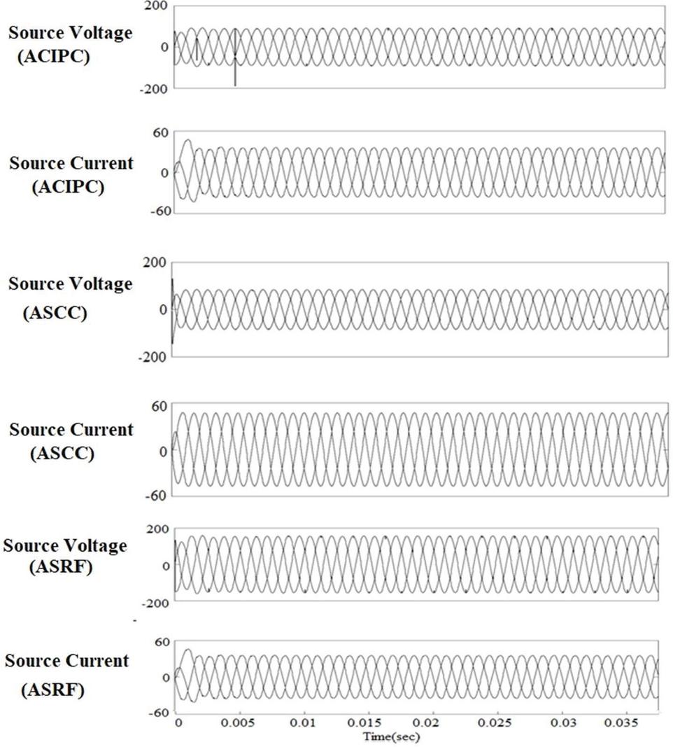
Figure 8 Source voltage and Source current for ACIPC, ASCC & ASRF strategy.
Simulation of aircraft active power filter with ACIPC, ASCC & ASRF strategy
As depicted in Figure 8, the results show that the THDs of source current for the ACIPC, ASCC, and ASRF strategy were 2.84%, 2.72%, and 2.78%, respectively. On the other hand, THDs of source voltage have been calculated by 1.88%, 1.65%, and 1.91% for the ACIPC, ASCC, and ASRF strategies. Therefore, the compensation has been completed within 0.0147 sec, 0.0100 sec, and 0.0072 sec respectively, for the ACIPC, ASCC, and ASRF strategy.
4.2.2 Compensation using advanced controllers
In this section, different advanced controllers/Algorithms have been used to optimize the conventional control strategies. Consequently, ANN controller, Fuzzy logic controller, Genetic algorithm, Adaptive blanket body search algorithm, and a combination of these have been used in the dc loop of the current control section to optimize control strategies.
Simulation of aircraft active power filter with ACIPC, ASCC & ASRF strategies using ANN
As depicted in Figure 9, the results show that the source current THDs for the ACIPC-ANN, ASCC-ANN, and ASRF-ANN strategy were 3.01%, 2.83%, and 2.73%, respectively. THDs of source voltage have been calculated by 1.78%, 1.55%, and 1.91% for the ACIPC-ANN, ASCC-ANN, and ASRF-ANN strategies. Therefore, the compensation has been completed within 0.0066 sec, 0.0066 sec, and 0.0068 sec respectively, for the ACIPC-ANN, ASCC-ANN, and ASRF-ANN strategy.
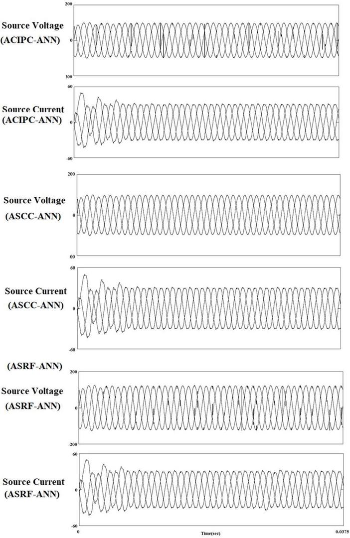
Figure 9 Source voltage and Source current for ACIPC, ASCC & ASRF strategies using ANN.
Simulation of aircraft active power filter with ACIPC, ASCC, & ASRF strategies using fuzzy logic controller
As depicted in Figure 10, the results indicate that the THDs of source current for the ACIPC-FLC, ASCC-FLC, and ASRF-FLC strategy were 2.33%, 2.22%, and 2.30%, respectively. On the other hand, THDs of source voltage have been calculated 1.03%, 1.01%, and 1.10% for the ACIPC-FLC, ASCC-FLC, and ASRF-FLC strategy. Therefore, the compensation has been completed within 0.0044 sec, 0.0066 sec, and 0.0067 sec for the ACIPC-FLC, ASCC-FLC, and ASRF-FLC strategy.
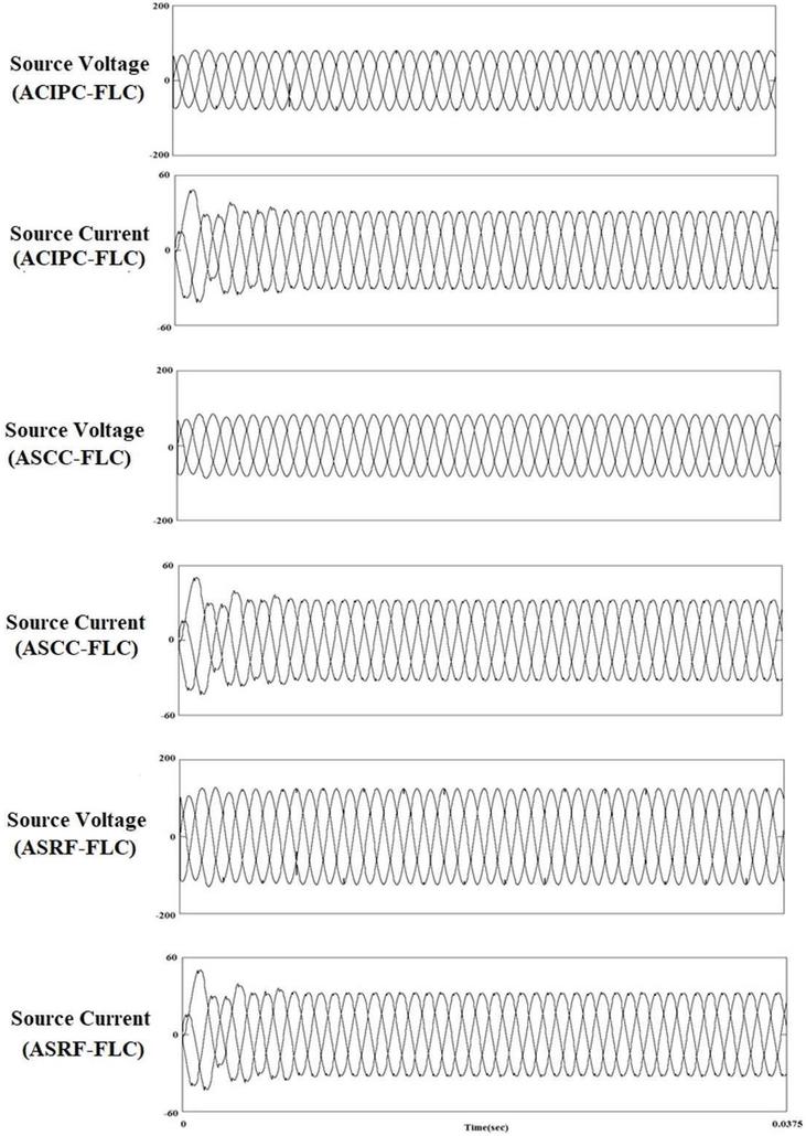
Figure 10 Source voltage and source current for ACIPC, ASCC & ASRF strategies using fuzzy logic controller.
Simulation of active power filter with ACIPC, ASCC, & ASRF strategies using genetic algorithm
As depicted in Figure 11, the results indicate that the THDs of source current for the CIPC-GA, SCC-GA, and SRF-GA strategy were 2.12%, 1.92%, and 2.11%, respectively. THDs of source voltage were 1.88%, 1.60%, and 2.01% for the ACIPC-GA, ASCC-GA, and ASRF-GA strategies. The compensation time at which the waveforms for source voltage and source current have become sinusoidal was 0.0066 sec, 0.0066 sec, and 0.0064 sec for the ACIPC-GA, ASCC-GA ASRF-GA strategy, respectively.
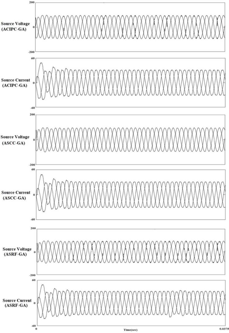
Figure 11 Source voltage and source current for ACIPC, ASCC & ASRF strategies using genetic algorithm.
Simulation of active power filter with ACIPC, ASCC, & ASRF strategies using adaptive blanket body search algorithm
As depicted in Figure 12, the results indicate that the THDs of source current for the ACIPC-ABBC, ASCC-ABBC, and ASRF-ABBC strategy were 2.72%, 2.42%, and 2.62%, respectively. THDs of source voltage were 1.07%, 1.06%, and 1.03% for the ACIPC-ABBC, ASCC-ABBC, and ASRF-ABBC strategy. The compensation time was 0.0064 sec, 0.0065 sec, and 0.0068 sec for the ACIPC-ABBC, ASCC-ABBC, and ASRF-ABBC strategy.
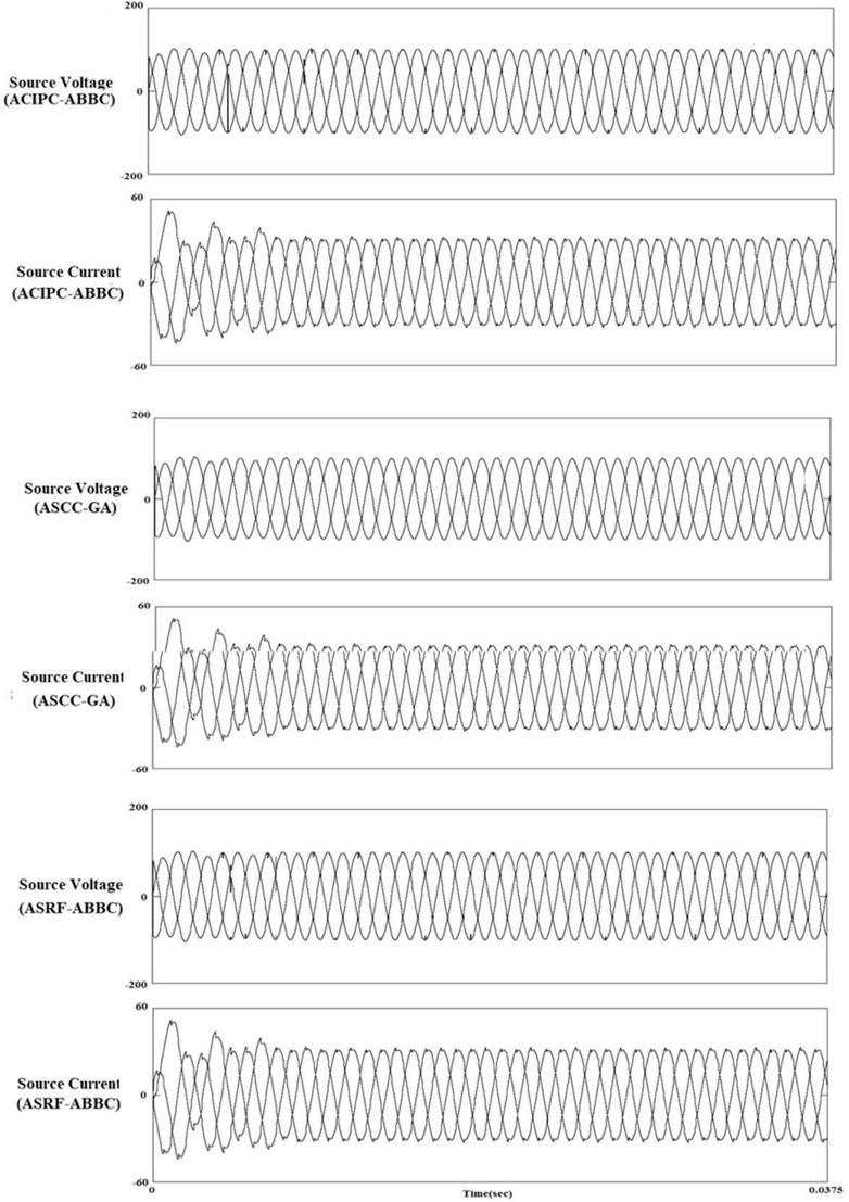
Figure 12 Source voltage and source current for ACIPC, ASCC & ASRF strategies using adaptive blanket body search algorithm.
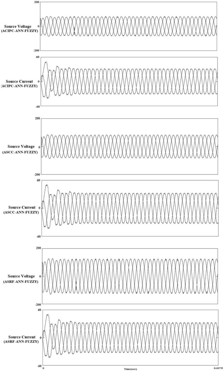
Figure 13 Source voltage and source current for ACIPC, ASCC & ASRF strategies using ANN & fuzzy logic controller.
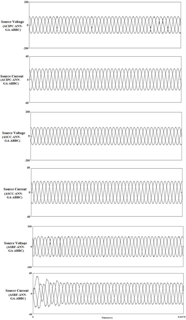
Figure 14 Source voltage and source current for ACIPC, ASCC & ASRF strategies using ANN with application of genetic & adaptive blanket body search algorithm.
Simulation of active power filter with ACIPC, ASCC, & ASRF strategies using ANN & fuzzy logic controller
The results in Figure 13 gave a picture of THDs of source current for the ACIPC-ANN-FLC, ASCC-ANN-FLC, and ASRF-ANN-FLC strategy, which were 2.30%, 2.20%, and 2.27%, respectively. THDs of source voltage were 1.01%, 1.01%, and 1.05% for the ACIPC-ANN-FLC, ASCC-ANN-FLC, and ASRF-ANN-FLC strategies. The compensation time was 0.0040 sec, 0.0065 sec, and 0.0065 sec for the ACIPC-ANN-FLC, ASCC-ANN-FLC, and ASRF-ANN-FLC strategies.
Simulation of active power filter with ACIPC, ASCC, & ASRF strategies using ANN with application of genetic & adaptive blanket body search algorithm
The results in Figure 14 gave a picture of THDs of source current for the ACIPC-ANN-GA-ABBC, ASCC-ANN-GA-ABBC, SRF-ANN-GA-ABBC strategy, and they were 0.93%, 0.40%, and 2.17%, respectively. THDs of source voltage were 1.15%, 0.78%, and 1.03% for the ACIPC-ANN-GA-ABBC, ASCC-ANN-GA-ABBCASRF-ANN-GA-ABBC strategy, respectively. The compensation time was 0.0040 sec, 0.0030 sec, and 0.0064 sec for the ACIPC-ANN-GA-ABBC, ASCC-ANN-GA-ABBC, and ASRF-ANN-GA-ABBC strategies, respectively.
5 Results and Discussions
A comparative analysis between the conventional control schemes and advanced control techniques has been carried out in this section. The basis for the comparison is total harmonic distortion (THD) calculated for source current & source voltage and the compensation time. The results and discussion henceforth have highlighted optimum filter selection based on the least THD and compensation time.
5.1 Analysis of Results Based on THD for Conventional Control Schemes for the Aircraft Supply System
THD of voltage and current has been computed for all three conventional control strategies modeled and simulated. Table 2 presents the THDs and compensation times of ACIPC, ASCC, ASRF control strategy, respectively, for the different load connected. THD-I (%) shows the THD of source current, and THD-V (%) shows the THD of source voltage, respectively.
Table 2 Source current, source voltage thd and compensation time of conventional control scheme
| Strategy | THD-I (%) | THD-V (%) | Compensation Time(sec) |
| ACIPC | 2.84 | 1.88 | 0.0147 |
| ASCC | 2.72 | 1.65 | 0.0100 |
| ASRF | 2.78 | 1.91 | 0.0072 |
From the results, as depicted in Figure 15, the ASCC strategy has been discovered best for the minimum THD, and ASRF has been found fastest based on compensation time.
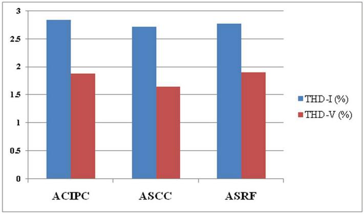
Figure 15 Bar chart of THD for source current and voltage of conventional control techniques.
Table 3 Source current, source voltage thds and compensation time of different advanced control techniques
| Strategy | THD-I (%) | THD-V (%) | Compensation Time(sec) |
| ACIPC-ANN | 3.01 | 1.78 | 0.0066 |
| ASCC-ANN | 2.83 | 1.55 | 0.0066 |
| ASRF-ANN | 2.73 | 1.91 | 0.0068 |
| ACIPC-FLC | 2.33 | 1.03 | 0.0044 |
| ASCC-FLC | 2.22 | 1.01 | 0.0066 |
| ASRF-FLC | 2.30 | 1.10 | 0.0067 |
| ACIPC-GA | 2.12 | 1.88 | 0.0066 |
| ASCC-GA | 1.92 | 1.60 | 0.0066 |
| ASRF-GA | 2.11 | 2.01 | 0.0064 |
| ACIPC-ABBC | 2.72 | 1.07 | 0.0064 |
| ASCC-ABBC | 2.42 | 1.06 | 0.0065 |
| ASRF-ABBC | 2.62 | 1.03 | 0.0068 |
| ACIPC-ANN-FLC | 2.30 | 1.01 | 0.0040 |
| ASCC-ANN-FLC | 2.20 | 1.01 | 0.0065 |
| ASRF-ANN-FLC | 2.27 | 1.05 | 0.0065 |
| ACIPC-ANN-GA-ABBC | 0.93 | 1.15 | 0.0040 |
| ASCC-ANN-GA-ABBC | 0.40 | 0.78 | 0.0030 |
| ASRF-ANN-GA-ABBC | 2.17 | 1.03 | 0.0064 |
5.2 Analysis of Results Based on THD for Among Advanced and Conventional Control Schemes for the Aircraft Supply System
Four artificial intelligent techniques ANN, FLC, GA, and ABBC algorithm, have been simulated. These techniques have been simulated alone as well as with their best combinations. The combinations used are ANN & FLC and GA, ABBC & ANN. These advanced techniques have been used to optimize the earlier discussed three conventional control techniques for different loads connected at different time intervals. As presented in Table 4, THD of voltage and current has also been computed for all advanced techniques. Their analysis has been done.
As shown in Figure 16 and Table 4, these results have been compared, and their analysis has been done. Then, it was found that the ASCC-ANN-GA-ABBC technique has been found best among all of them.
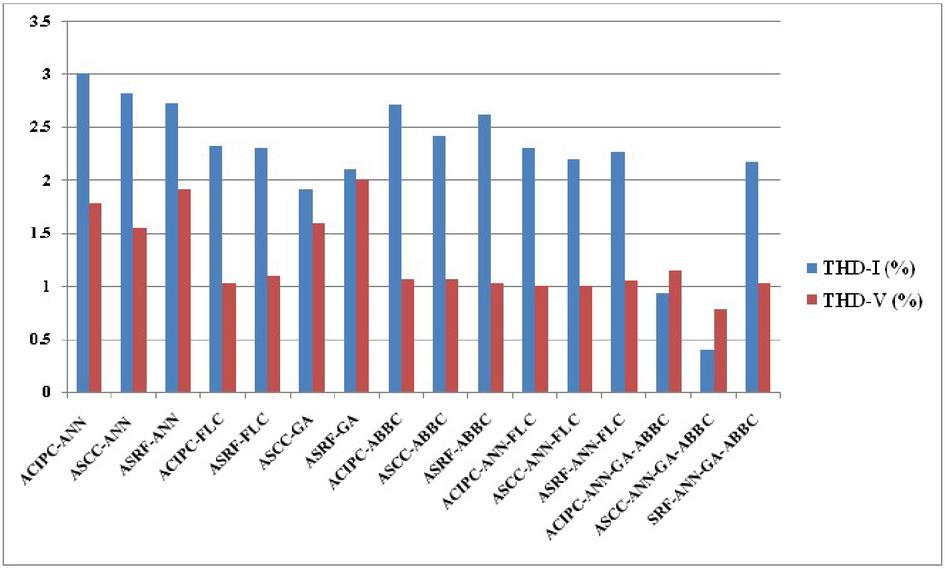
Figure 16 Bar chart of THD for source current and voltage of advanced control techniques.
Table 4 Comparisons of Strategies employed in AAPF
| Optimum Control | Optimum Control Strategy | ||
| Compensation | Strategy Based | Based on Source THD | |
| Technique | on Compensation | THD(Current) | THD(Voltage) |
| Conventional | ASRF | ASCC | |
| Advanced | ASCC-ANN-GA-ABBC | ||
| Conventional & Advanced | ASCC-ANN-GA-ABBC | ||
6 Conclusion
In this paper, a comparison has been made among conventional and advanced control techniques used in AAPF. Three types of loads have been used to check each control technique’s ability individually or in combination with others. The basis to check the ability was THD and the compensation time (speed). The optimum control technique has been found as the Aircraft Sinusoidal Current control Strategy for minimum THD of current and voltage in conventional control strategies. On the other hand, the fastest compensation has been achieved by the Aircraft Synchronous reference frame Strategy. Finally, among advanced and conventional control techniques, ASCC-ANN-GA-ABBC has been discovered as best for minimum THD and fastest compensation.
References
[1] Emadi, K., and M. Ehsani. 2000. Aircraft Power Systems: Technology, State of the art, and future trends. IEEE Aerospace and Electronic Systems Magazine 15:28–32.
[2] Eid, A., H. El-Kishky, M. Abdel-Salam, and T. El-Mohandes. 2010. VSCF aircraft electric power system performance with active power filters. 2010 42nd Southeastern Symposium on System Theory (SSST 2010).
[3] Zhang, X., C. L. Bowman, T. C. O’Connell, and K. S. Haran. 2018. Large electric machines for aircraft electric propulsion. IET Electric Power Applications 12:767–779.
[4] Peng, F. Z., H. Akagi, and A. Nabae. 1990. A new approach to harmonic compensation in power systems-a combined system of shunt passive and series active filters. IEEE Transactions on Industry Applications 26:983–990.
[5] Chen, D., S. Xie, T. Guo, and B. Zhou. 2005. Shunt active power filters applied in the aircraft power utility. IEEE 36th Conference on Power Electronics Specialists, 2005.
[6] Khalid, S. 2016. Optimized Aircraft Electric control system based on adaptive tabu search algorithm and Fuzzy Logic Control. Indonesian Journal of Electrical Engineering and Informatics (IJEEI) 4:149–164.
[7] Khalid, S. 2016. Application of adaptive tabu search algorithm in hybrid power filter and shunt active power filters: Application of ATS algorithm in HPF and APF. Pages 276–307 in Sustaining power resources through energy optimization and engineering. IGI Global, NJ, USA.
[8] Khalid, S. 2017. THD and Compensation time analysis of three-phase shunt active power filter using adaptive blanket body cover algorithm. Pages 1–22 in Applied Computational Intelligence and Soft Computing in Engineering. IGI Global, NJ, USA.
[9] Khalid, S. 2016. THD and compensation time analysis of three-phase shunt active power filter using adaptive Spider Net Search Algorithm (ASNS). International Journal of Computing and Digital Systems 5:487–504.
[10] Vasant, P., T. Ganesan, and I. Elamvazuthi. 2012. Improved Tabu search recursive fuzzy method for crude oil industry. International Journal of Modeling, Simulation, and Scientific Computing 03:1150002.
[11] Jiang, Y.-hua, and Y.-wei Chen. 2009. Neural network control techniques of hybrid active power filter. 2009 International Conference on Artificial Intelligence and Computational Intelligence.
[12] Bhattacharya, A., and C. Chakraborty. 2011. A shunt active power filter with enhanced performance using ANN-based predictive and adaptive controllers. IEEE Transactions on Industrial Electronics 58:421–428.
[13] Chaijarurnudomrung, K., K.-N. Areerak, K.-L. Areerak, and A. Srikaew. 2011. The controller design of three-phase controlled rectifier using an adaptive tabu search algorithm. The 8th Electrical Engineering/ Electronics, Computer, Telecommunications and Information Technology (ECTI) Association of Thailand – Conference 2011.
[14] Khalid, S., B. Dwivedi, and V. M. Mishra. 2015. Constant instantaneous power based controller for a shunt active power filter under balanced, unbalanced, and distorted supply conditions. International Conference on Computing, Communication & Automation.
[15] Akagi, H., Y. Kanazawa, and A. Nabae. 1984. Instantaneous reactive power compensators comprising switching devices without energy storage components. IEEE Transactions on Industry Applications IA-20:625–630.
[16] Aredes, M., J. Hafner, and K. Heumann. 1997. Three-phase four-wire shunt active filter control strategies. IEEE Transactions on Power Electronics 12:311–318.
[17] Khalid, S., and B. Dwivedi. 2014. Application of AI techniques in implementing shunt APF in Aircraft Supply System. Advances in Intelligent Systems and Computing: 333–341.
[18] Kumar, N., and V. M. Mishra. 2020. Comparative critical analysis of artificial intelligent technique and conventional control technique applied in series filter for harmonic reduction. Applications of Artificial Intelligence in Electrical Engineering: 129–143.
[19] Akagi, H., S. Ogasawara, and K. Hyosung. 1999. The theory of instantaneous power in three-phase four-wire systems: A comprehensive approach. Conference Record of the 1999 IEEE Industry Applications Conference. Thirty-Forth IAS Annual Meeting (Cat. No.99CH36370).
[20] Khalid, S., and B. Dwivedi. 2014. Comparative evaluation of various control strategies for shunt active power filters in aircraft power utility of 400 Hz. Majlesi Journal of Mechatronic Systems 3:1–5.
[21] Khalid, S., A. Tripathi, and V. M. Mishra. 2013. Comparison of constant instantaneous power control & synchronous rotating frame strategy for total harmonic reduction in aircraft system (400 Hz). Advanced Materials Research 768:287–297.
[22] Kumar, P., and A. Mahajan. 2009. Soft computing techniques for the control of an active power filter. IEEE Transactions on Power Delivery 24:452–461.
[23] Khalid, S. 2018. Performance evaluation of adaptive tabu search and genetic algorithm optimized shunt active power filter using neural network control for aircraft power utility of 400 Hz. Journal of Electrical Systems and Information Technology 5:723–734.
[24] Khalid, S. 2019. A Comparative Study of Neural Network and Fuzzy Logic Control Based Active Shunt Power Filter for 400 Hz Aircraft Electric Power System. Pages 96–107 in Deep learning: Concepts, methodologies, tools, and applications. Chapter IGI Global, NJ, USA.
[25] Homaifar, A., and E. McCormick. 1995. Simultaneous design of membership functions and rule sets for fuzzy controllers using genetic algorithms. IEEE Transactions on Fuzzy Systems 3:129–139.
[26] Khalid, S. 2018. Genetic Algorithm Application in Shunt Active Power Filter Applied In Constant Frequency Aircraft System. Indonesian Journal of Electrical Engineering and Informatics (IJEEI) 6:112–119.
[27] Khalid, S. 2016. Performance evaluation of GA optimized shunt active power filter for constant frequency aircraft power system. Indonesian Journal of Electrical Engineering and Informatics (IJEEI) 4:112–119.
[28] Khalid, S., and B. Dwivedi. 2013. GA-Fuzzy Application in SAF & its comparative analysis with conventional techniques in aircraft system. 2013 International Conference on Control, Automation, Robotics and Embedded Systems (CARE).
[29] Khalid, S. 2018. Analysis of shunt active power filter using adaptive blanket body cover algorithm (ABBC) in aircraft system. in Advances in Computer and Electrical Engineering:63–80.
[30] MIL-STD-704F. 2004. Aircraft electric power characteristics.
[31] Arseneau, R., Y. Baghzouz, J. Belanger, K. Bowes, A. Braun, A. Chiaravallo, M. Cox, S. Crampton, A. Emanuel, P. Filipski, E. Gunther, A. Girgis, D. Hartmann, Shu-Dong He, G. Hensley, D. Iwanusiw, W. Kortebein, T. McComb, A. McEachern, T. Nelson, N. Oldham, D. Piehl, K. Srinivasan, R. Stevens, T. Unruh, and D. Williams. 1996. A survey of North American electric utility concerns regarding non-sinusoidal waveforms. IEEE Transactions on Power Delivery 11:73–78.
[32] IEEE Standard 519. 1992. IEEE Recommended practices and requirements for harmonics.
[33] BS EN 61000-3-2. 1995. Electromagnetic compatibility (EMC) – Part 3: Limits – Section 2: Limits for harmonic current emissions (equipment input current less than or equal to 16A per phase).
[34] EC 555-2. 1982. Disturbances in Supply Systems Caused by Household Appliances and Similar Equipment.
[35] IEC 61000-3-2. 2000. Power Quality Measurement Methods.
[36] IEEE Std. 128. 1976. IEEE guide for aircraft electric systems.
Biographies

Saifullah Khalid received the bachelor’s degree in Electronics & Telecommunication engineering from North Maharashtra University in 2001, the master’s degree in Electrical Engineering from UP Technical University in 2004, and the philosophy of doctorate degree in Electrical Engineering from AKTU in 2017, respectively. He is currently working as Senior Manager (ATM) & Associate Member (R&D) at Airports Authority of India, Lucknow. His research areas include optimization algorithms, aircraft system, active power filter, air traffic management, and innovation. He has published around 100 research papers in various International Journals and Conferences, including IEEE, Elsevier, Springer, and many others. He has authored four books, edited two books, and contributed six Chapters in edited books.

Sonia is currently Professor in the Decision Sciences Area at IIM Lucknow. She has been working at IIM Lucknow since May 2005 where she teaches Optimization, Statistics and Managerial Mathematics to Post Graduate, Doctoral and Executive students. She has also visited NTU, Singapore as Visiting Associate Professor for one year during 2017–18. She obtained her doctoral degree from IIT Delhi and master’s degree from IIT Roorkee. Her research interests include Transportation & Assignment Problems, Network Flow Problems and Multi Criteria Decision Making Problems among others.

Narendra Pratap Singh received Master’s degree in Computer Science from Jawaharlal Nehru University in 2002. He is currently working as Assistant General Manager (ATM) & Associate Member (R&D) at Airports Authority of India, Lucknow. His research areas include optimization algorithms, air traffic management, and innovation. He has published various research papers in International Journals and Conferences.

Khadim Moin Siddiqui is currently working as an Associate Professor and Head of Department in Department of Electrical Engineering and Department of Electrical & Electronics Engineering in Sri Ramswaroop Memorial College of Engineering and Management (SRMCEM), Lucknow. He has received the B.Tech. degree in Electronics Engineering from Azad Institute of Engineering & Technology (AIET), Lucknow (Uttar Pradesh Technical University, Lucknow) in 2007, the M.Tech. degree in Power Electronics & Drives with Honors (Electrical Engineering) from Madan Mohan Malaviya Engineering College, Gorakhpur (Gautam Buddha Technical University, Lucknow) in 2012 and Ph.D. degree in Electrical Engineering funded by Technical Education Quality Improvement Program Phase-II from Institute of Engineering & Technology, Lucknow (Dr. A.P. J. Abdul Kalam Technical University, Lucknow) in 2017. He has published more than 40 research papers in international journals, 15 papers presented in the national as well as international conferences and published four book chapters. He has received best research paper awards in one national and in two 2 international conferences. He has published two books in the field of Electrical Engineering & Technology. He has more than 13 years of experience. He is the editorial board member of an international journal and reviewer of many reputed journals such as Elsevier’s Mechanism and Machine Theory, IEEE Industry Applications Society, International Journal on Electrical Engineering and Informatics, Indonesia, Global Journals, USA and active reviewer of IEEE International and National Conferences. He is an Advisor of IEEE Student Branch, SRMCEM, Lucknow and also advisor of IEEE Signal Processing Society. He is an active volunteer and organized many programs of national as well as international levels such as webinars/FDPs,/QIP/Conference. He is an IEEE Senior member from November 2020. He has delivered Expert Lectures in the field of power electronics & drives, signal processing in many institutions and also in IEEE UP Section. He has attended and participated in more than 40 FDPs/STTPs/Webinars/Conferences. He has chaired session in many international conferences. His research area of interest includes Electrical Machines, fault diagnosis and health monitoring of induction motors and power transformers, signal processing, multilevel inverters and smart grid, Renewable Energy, Energy Efficiency & Conservation. He has been awarded IEEE Young Professional Star of the March Month 2021 and Outstanding Chapter Advisor Award by IEEE UP Section. He has served as a Lead Guest Editor in Distributed Generation and Alternative Energy Journal, USA and Editor, IEEE UP Section Newsletter 2021. Currently, he is a Lead Guest Editor of IET Renewable Power Generation and Guest Editor of IET Generation, Transmission & Distribution Journals. He is an Executive committee Member in Membership Development of IEEE UP Section (R10), India.
Distributed Generation & Alternative Energy Journal, Vol. 37_4, 899–928.
doi: 10.13052/dgaej2156-3306.3742
© 2022 River Publishers