Design and Control of an Off Board Battery Charger for Electric Vehicles
Uzma Dar1,*, Anwar Shahzad Siddiqui1 and Farhad Ilahi Bakhsh2
1Department of Electrical Engineering, Jamia Millia Islamia, New Delhi, India
2Department of Electrical Engineering, National Institute of Technology Srinagar, Srinagar (J&K), India
E-mail: uzma.manzoor97@gmail.com; assiddiqui@jmi.ac.in; farhad@nitsri.ac.in
*Corresponding Author
Received 14 September 2021; Accepted 21 November 2021; Publication 22 April 2022
Abstract
The rise in the penetration of electric vehicles has led to the increased interest in the charging technologies. Controlled charging and vehicle to grid power transfer is being given much importance. This paper proposes an off board charger (three phase) for charging the batteries used in electric vehicles. The proposed charger has a bidirectional power transfer capability so as to transfer power back to the utility grid. The topology proposed is simple and less costly as it has fewer elements. The charger has two converters, a three phase ac-dc converter for conversion of ac into dc and bidirectional dc-dc converter. The technique called Vector control is used to control ac-dc converter which allows controlling of active and reactive power independently. The control strategy proposed here provides a better control and leads to a better performance while maintaining unity power factor at input. The charging algorithm designed is such that it is able to maintain voltage at dc link at desired value. The charging algorithm is designed for lithium ion batteries and the combined Constant Current Constant Voltage (CC-CV) method of charging is used because it is simple and easy to implement. The proposed electric vehicle charger changes the mode of charging with change in State of Charge (SOC). The different modes are switched and the suitable reference is generated based on the different charging characteristics of a battery. The proposed charger is modeled in MATLAB-Simulink. The working operation of both forward and reverse power transfer mode has been analyzed. The proposed charger is able to maintain the unity power factor operation. The simulation results of all modes validate the design and control of the proposed charging topology.
Keywords: Bidirectional charging, grid to vehicle (G2V), pulse width modulation (PWM), unity power factor, vehicle to grid (V2G).
1 Introduction
Over the past decades, the effect of the conventional transport systems which run on fossil fuels on the environment has paved way to the reintroduction of the electrical transport facility. These electric transport facilities have proved to be a favorable approach so as to green the transportation. Moreover, the concerns regarding the climate change have decreased. The various concerns related to the environment and demand for green energy has contributed to the increase in the electric vehicles as a means of transport [1–4]. In India, transport systems are the major contributors of harmful emissions, therefore the deployment of electric vehicles becomes necessary in order to decrease the pollution [5, 6].
In conventional power systems, the load always consumes energy and the transmission of energy is in one direction only. However, by developing electric vehicles as energy storing elements they will be able to interact with the grid, so the technology called Vehicle to Grid (V2G) has been extensively studied. The fast conversion of conventional vehicles into electric vehicles can affect the peak hours of the load profile which can lead to problems in grid operation. The increased load on the power network due to huge number of electric vehicles being deployed can be decreased by exploiting bidirectional charging method for charging of electric vehicles. The connection of an electric vehicle with a power grid can help to achieve many remarkable features like load balancing, support to active power, control of active power, and renewable energy sources support [7, 8].
The battery is one of the important components of any electric vehicle. The power for running of any electric vehicle is obtained from the energy stored in a battery in the form of DC. This battery will require charging as per the requirement. The robustness and the efficiency in a charging method are important criteria for the global adoption of electric vehicles. Lithium ion batteries are used in electric vehicles because power density and efficiency is high. Moreover, these batteries have less weight and long lifecycle with less self-discharge rate [9].
Chargers can be categorized into two groups based on the placement of charging components, on board and off board [10]. Conventionally, on-board chargers were used to charge the batteries but nowadays more focus is on off board chargers which are installed outside the electric vehicles and are capable of higher energy transfer. The on board circuits limit the power level and charging rate [11]. The presence of power conversion units in charging stations leads to the reduction of size and weight of the system [12].
A typical bidirectional charger as shown in Figure 1 has two converters: ac-dc converter for conversion of ac into dc (forward power transfer) and dc into ac (reverse power transfer) and bidirectional dc-dc converter. Single-phase converters have a disadvantage of unbalanced loading which leads to problems in a power grid. The three phase converters have a benefit of charging the battery in comparatively smaller time and also boost charging. Moreover, the three phase converter draws the symmetrical current from the grid which is balanced irrespective of any load. Therefore, the three phase converters are better than the single phase ones [13]. An inclusion of the bidirectional dc-dc converter allows bidirectional transfer of power, eradicates the dependency of selecting the dc link voltage on the basis of voltage of a battery and provides galvanic isolation. Moreover, the battery is protected from the ripple in dc link and also the charging current smoothens because of the filters used at the end of the dc-dc converter. Furthermore, it helps in converting the intermediary dc voltage into the controlled one which is needed by the vehicle [14, 15]. Different topologies that can be used for ac-dc and dc-dc converters are presented in [16].
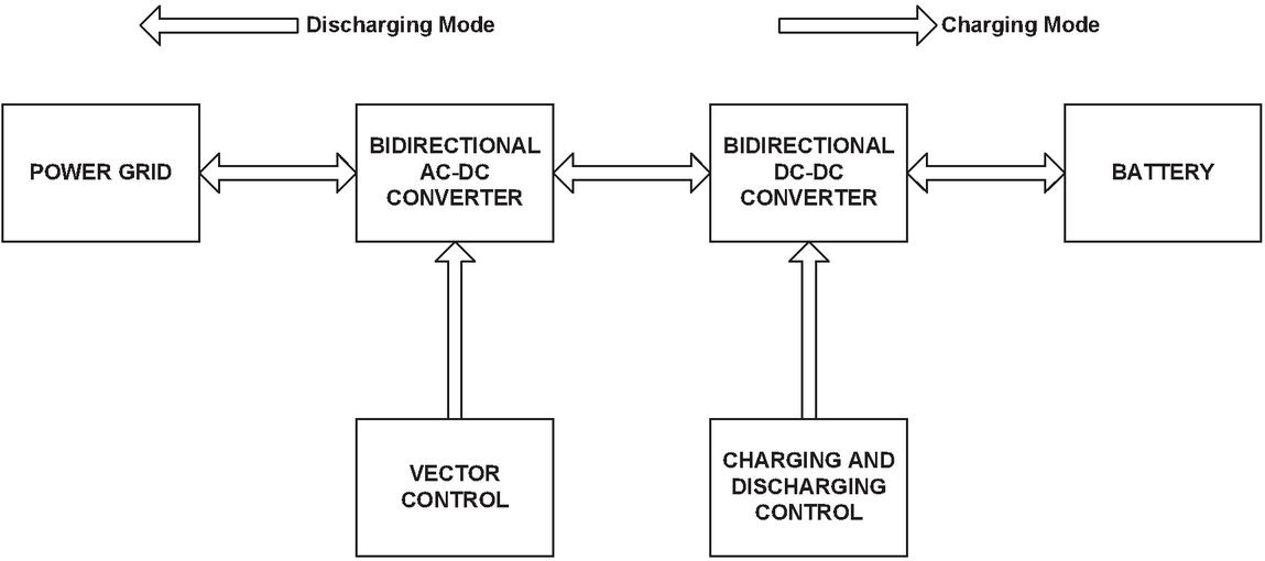
Figure 1 A typical bidirectional charger with various controls.
This paper proposes a circuit topology and a proper control algorithm for an off board charger for charging the batteries of electric vehicles. Moreover, this control strategy is able to operate the system with unity power factor. The algorithm used enhances the performance of this particular system by providing a better control. Vehicle to Grid technology for reverse power transfer is implemented so as to feed power back to the grid using stored energy of a battery. The grid-end ac-dc converter acts as a boost converter producing higher voltage at output than the input side peak voltage (line to line). This converter draws currents which are close to sinusoidal one from the ac mains. Moreover, these converters are also able to regulate the output voltage which is dc and can also adjust the input power factor. There are various topologies of dc-dc converters that can be used in an electric vehicle charger but depending on the need the particular topology can be chosen. In the paper, a half-bridge topology is used. The advantages of using the half-bridge converter are that the topology requires less storage elements and two switches. This requires less space and eventually less cost. Also, the ripple in charging is very low and they have both voltage and current control capabilities [17]. This topology leads to control and design simplicity. The organization of the paper is as follows: Section 2.1 presents the circuit topology of the proposed three phase off board charger, Section 2.2 explains the different control strategies used in the proposed charger, Section 2.3 includes all the simulation results and Section 3 concludes the paper.
2 Proposed Three Phase Off Board Charger
The proposed charger works in a bidirectional manner. The grid power is used to charge the battery in a controlled fashion called Grid to Vehicle (G2V) mode and the stored energy in the battery is used to feed power back to the grid called Vehicle to Grid (V2G) mode.
2.1 Circuit Topology
A full circuit diagram of a proposed battery charger for electric vehicles which gets its power from a three phase power grid is shown in Figure 2. It comprises of a three phase bidirectional voltage source converter for ac-dc conversion having inductors on the grid side and a dc-dc converter to serve various purposes like stepping-down the voltage, bidirectional power transfer, regulation and many more. These two converters are connected via a dc link capacitor whose voltage needs to be maintained at a particular value for a proper power transfer. LC filter is connected at the battery side so as to further smoothen the current. Then there is a lithium ion battery which is to be charged with a proper algorithm.
It is evident from the figure that during forward operation when the S7 is switched on, voltage of inductor is given by Equation (1),
| (1) |
where V is the inductor voltage.
When S8 is switched on and S7 is off, the value is given by Equation (2),
| (2) |
During reverse operation, while S7 is on, the value of inductor voltage is given by Equation (3),
| (3) |
When S8 is on, the value is given by Equation (4),
| (4) |
For proper power transfer (both forward and reverse), these two converters are controlled using suitable control algorithm. For voltage source converter (VSC) which is discussed in Section 2.2, vector control is used and for dc-dc converter combined CC-CV control is used. The control is such that the battery gets charged safely and in less time.
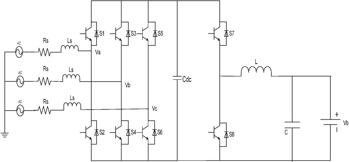
Figure 2 Circuit diagram of a proposed off board charger.
2.2 Control Strategy
2.2.1 VSC control
The control scheme provided for a three phase ac-dc converter is such that the voltage at dc capacitor remains at a desired value and also the system is operated at a unity power factor. Therefore, the technique used here is similar to that of a vector control of three phase induction motor. Here, the outer loop is used to control voltage at dc link whereas in motors the outer loop is used to control speed. Also, the active and reactive powers are controlled by the “d-axis and q-axis” current control loops respectively, whereas in motors, flux and torque are controlled by the “d-axis and the q-axis” currents respectively [18]. In this technique, grid voltages and line currents of a three phase system are transformed into an equivalent two phase system, which is known as a “stationary reference frame”. These values are then converted into a reference frame known as synchronous reference frame, which rotates around the grid frequency. The current components corresponding to the active and reactive power are controlled independently in a synchronous reference frame.
The control scheme starts with the dc link voltage reference set at 650 V as VSC will increase the voltage and reference “q-axis” current set at zero because power factor has to be maintained unity at the input side. In this control, the reference values of the voltage and currents are compared with their measured values and then the error is accordingly tuned using PI controller and the reference signal is generated using PWM technique. The control diagram for ac-dc converter is presented in Figure 3. Firstly, the grid voltage and grid current are transformed into active and reactive components using abc to dq transformation. PLL is used for synchronization. For controlling V, the reference value of voltage at dc link and the measured value of the same are compared and then by using a PI controller the error is tuned so as to get a proper signal. Secondly, the active and the reactive currents are compared with their reference values respectively and accordingly tuned to generate the reference values using again a PI controller. By fine-tuning PI controller the fast dynamic response can be attained.
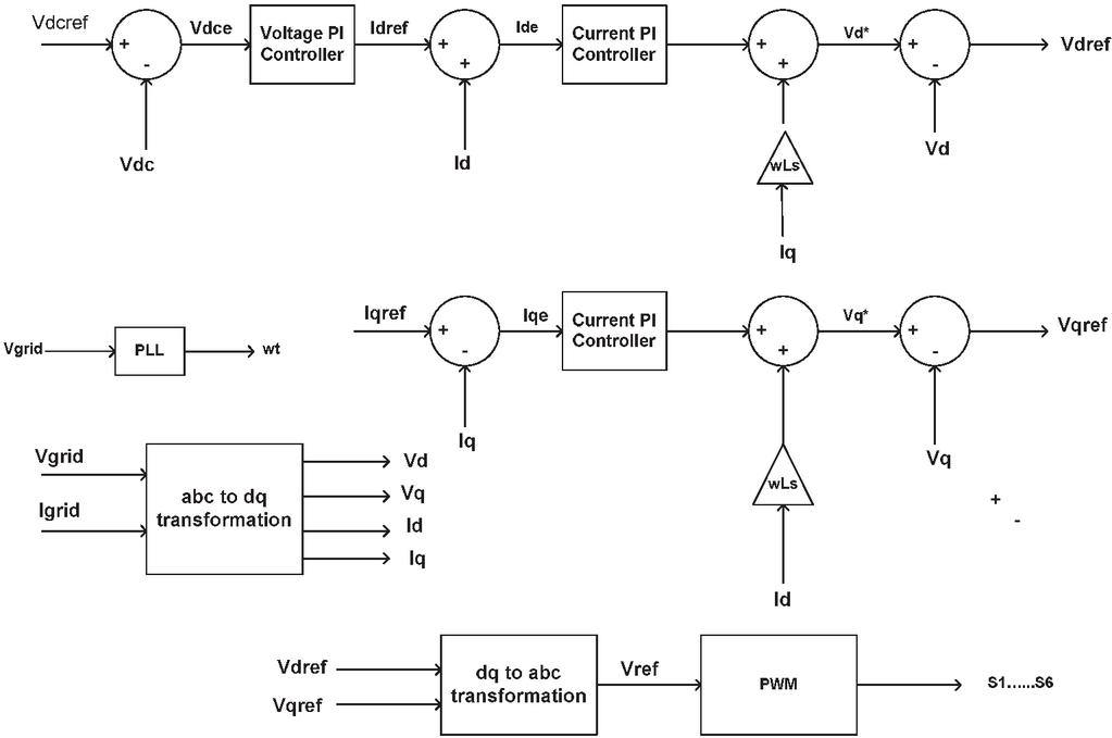
Figure 3 Control strategy for three phase VSC.
After executing the control of voltage and current loops, the values of V and V are generated and these are then transformed into reference voltages using dq to abc transformation and then by means of sinusoidal PWM method, the switching pulses for VSC are produced.
2.2.2 DC-DC converter control
PWM method is used to control this bidirectional dc-dc converter. A technique called as battery charging current control is used to get the reference signal for PWM generation used for generating pulses. The charging control strategy is devised so as to fast charge the batteries and also to ensure safe charging of batteries. In this control, the reference values of charging current and battery voltages are compared with the measured values and then accordingly tuned using PI controller. The reference produced is used for PWM generation. The charging strategy used here is CC-CV method of charging. In this charging algorithm, the battery at first is charged by using a constant current until a predetermined maximum charging voltage is achieved. After that the charging voltage is kept constant until the current decreases to a predetermined minimum value.
It has been seen that at the start of charging with any original level of state of charge (SOC), the voltage of a cell increases to a higher value and it decreases to its original value when the SOC increases from its original SOC value to 2–4% of the original SOC value. If value of charging current is high in this mode then cell voltage will increase further and will lead to rise in temperature in a cell, which will eventually cause the damage to active material. Also, the voltage of a cell should not go further down below its minimum preset range during discharging mode. In order to avoid this overcharging, initial charging mode is added to the charging strategy which will charge the battery with less charging current until a sufficient increase in the SOC is reached [19]. After that the battery will be charged in constant current mode with a ‘C’ charging rate to ensure fast charging. When 90% SOC is reached, the control will switch to constant voltage mode. In this mode, to ensure that the charging current of battery does not go beyond its charging rate current and also terminal voltage of battery is maintained at a constant value, an inner current control loop is introduced. While maintaining the terminal voltage of a battery at a constant value, the charging current of battery decreases.
In initial charging mode and constant charging mode, the current reference which is decided on the basis of maximum charge that can be accepted by the lithium ion battery is compared with the measured values of current and then is tuned by a PI controller. A reference signal is generated which is then used to generate pulses using PWM method. Figure 4 shows the control diagram of both initial charging mode and constant charging mode. The charging rate at the start of charging is ‘C/2’ and throughout constant current charging mode is ‘C’.
During constant voltage mode, the reference and the actual voltage of battery is compared and then the signal generated is compared with the actual current of battery. The signal generated is then fed to a PI controller which will generate the reference for further generation of switching pulses for dc-dc converter. The control diagram for this mode is shown in Figure 5.
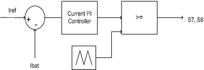
Figure 4 Control strategy for initial and constant current charging mode.
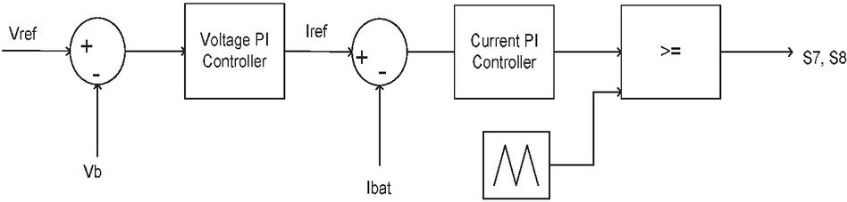
Figure 5 Control strategy for constant voltage charging mode.
2.2.3 V2G control
V2G mode can be realized by controlling the dc-dc converter which requires the battery discharging current reference. In this control process, the battery discharging current reference (I) and the actual value of discharging current (I) is compared and then the error is fed to the PI controller which then controls it accordingly to generate the reference for PWM generation as can be seen in Figure 6. Then the PWM method is used for the pulse generation for the switches of dc-dc converter. This control leads to the reverse power flow and can permit the transmission of power from the battery to the grid hence acting as a source.
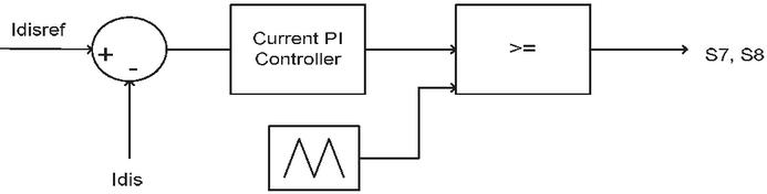
Figure 6 Control Strategy for V2G Mode.
2.3 Simulation Results
The proposed system is modeled and then the simulation is done for a three phase system with rms voltage of 415 V, frequency of 50 Hz and the voltage at dc link is maintained at 650 V. The values of various parameters taken are shown in Table 1. These values are calculated using the equations given below [19]:
| (5) | |
| (6) | |
| (7) |
The charging of a battery is done in three modes, initial charging mode, constant current charging mode, and constant voltage charging mode. The charging rate ‘C’ of these modes is different in order to achieve the safe and quick charging of a battery. The charging is done at ‘C/2 rate in initial charging mode so as to protect the battery from overcharging which will damage the battery. Therefore, the charging current of battery is around 125A and the power drawn is 7 kW which is clearly shown in Figure 7. The voltage at dc link settles at 650 V and unity power factor is maintained (Q 0). The SOC is around 27% which is increasing as the battery is charging and battery voltage is also increasing. In order to switch from one mode to other, the proper algorithm is provided. The control itself changes the charging mode from initial charging mode to constant current charging mode. While changing from one mode to another, it is observed from the Figure 8 that the dc link voltage goes down to 640 V but reaches 650 V again in few milliseconds thus validating the control method. The battery charging current changes its value from 125A to 250A. Similarly, the voltage and SOC of a battery show abrupt change in values while moving from one mode to the other although the reactive power is maintained at zero.
Table 1 System parameters
| Battery Nominal Voltage | 56 V |
| Battery Capacity | 250 Ah |
| Power rating of Charger | 15 kW |
| Inductor | 7 mH |
| DC link Capacitor | 4.8 mF |
| Battery side LC filter | 600 H, 200 F |
In constant current charging mode, a constant value of current is maintained which is around 250A. This is achieved by comparing the reference and the measured value of charging current and proper tuning of the PI controller which will generate the suitable reference signal for this mode of charging. During this mode, the charging is done at ‘C’ rate so as to reduce the charging time. As can be seen from the Figure 9, the power drawn in this mode is 13.6 kW. The voltage at dc link is at a desired value of 650 V and power factor of unity is achieved as can be seen from the reactive power waveform. The battery voltage is increasing and SOC which is about 48% can also be seen increasing. The results validate the process of constant current charging method.
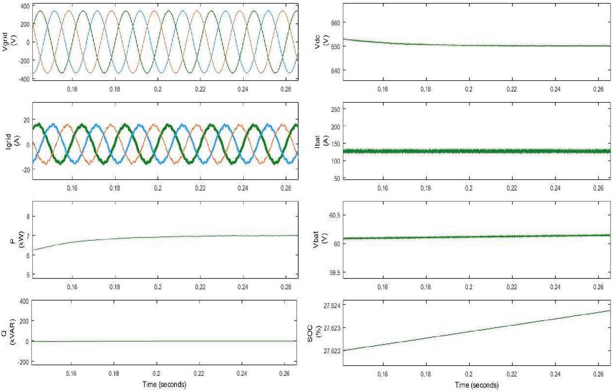
Figure 7 Performance during initial charging mode.
In constant voltage charging mode, charging is done by maintaining a constant voltage which is the fully charged voltage of a battery and hence the charging current decreases gradually. This mode avoids overcharging of batteries. In this mode, inner current control loop is added to check the increase in charging current. This mode is switched when the SOC reaches above 90%. Figure 10 shows the change in different parameters. During this mode, again dc link voltage is 650V and unity power factor is achieved as the reactive power settles on zero. The battery voltage attains a constant value of around 66V and SOC is increasing as the battery is still in charging mode.
V2G mode allows the reverse power transfer so as to give back power to the grid. The discharging current reference is compared with the actual discharging current and tuned accordingly so as to generate the suitable reference signal for discharging operation. In this mode, the active power is 7 kW and the discharging current is around 125 A as can been seen from the Figure 11. The voltage at dc link is maintained at 650 V. Here, reactive power is zero which means unity power factor operation is maintained. The battery voltage and SOC is decreasing as the discharging operation is taking place.
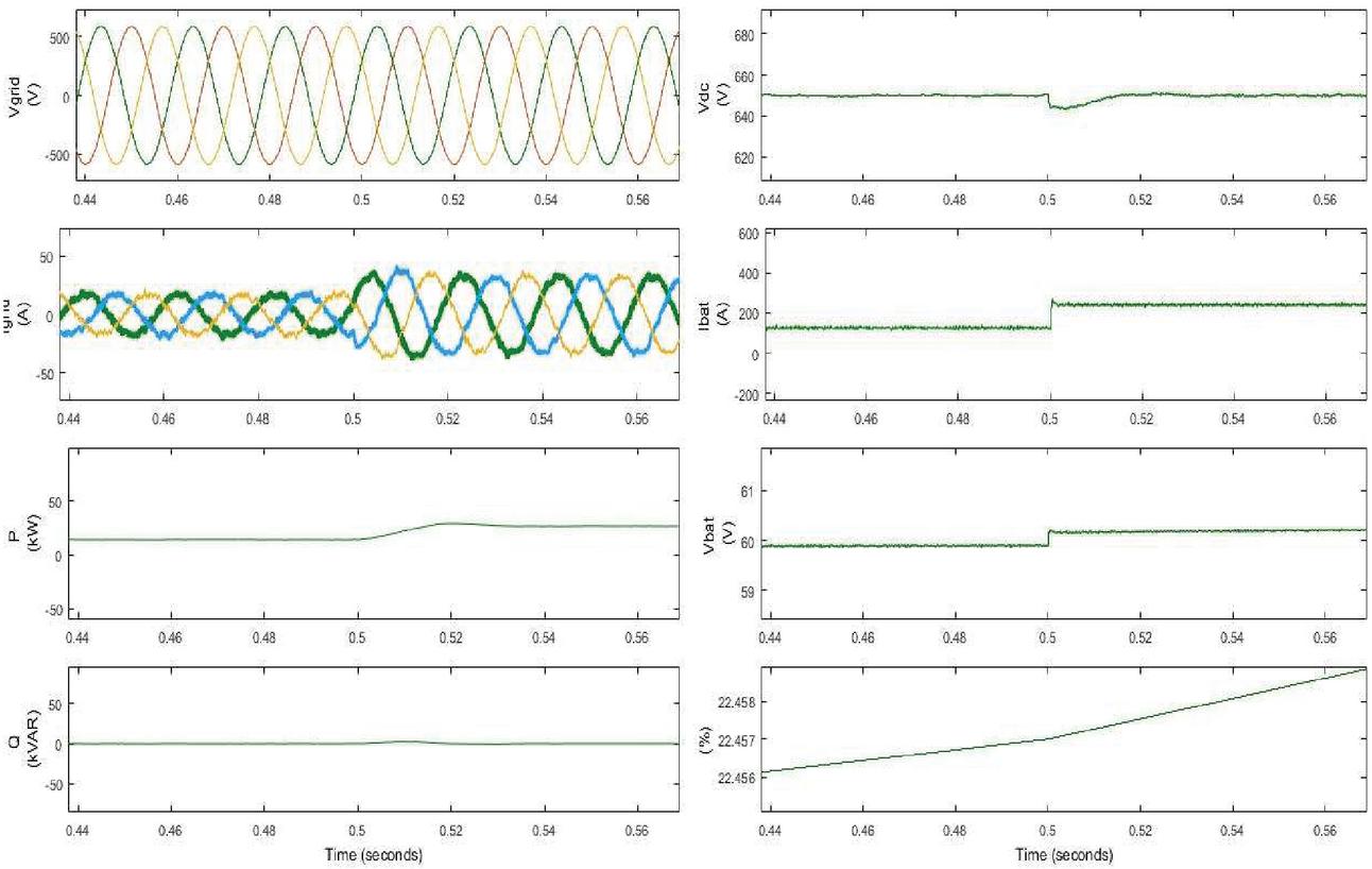
Figure 8 Performance while changing from initial charging to constant current mode.
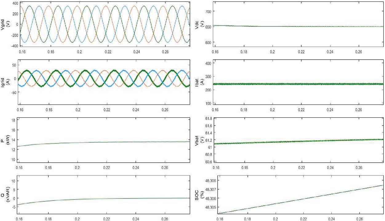
Figure 9 Performance during constant current charging mode.
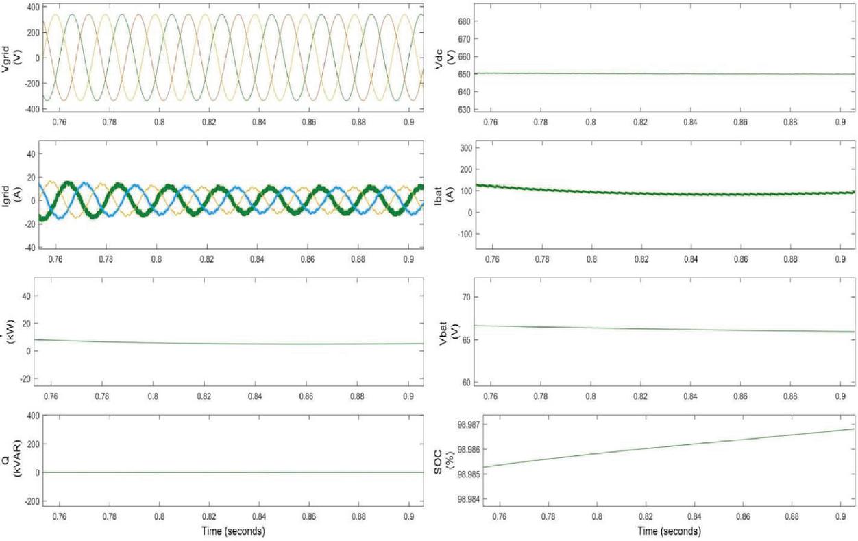
Figure 10 Performance during constant voltage charging mode.
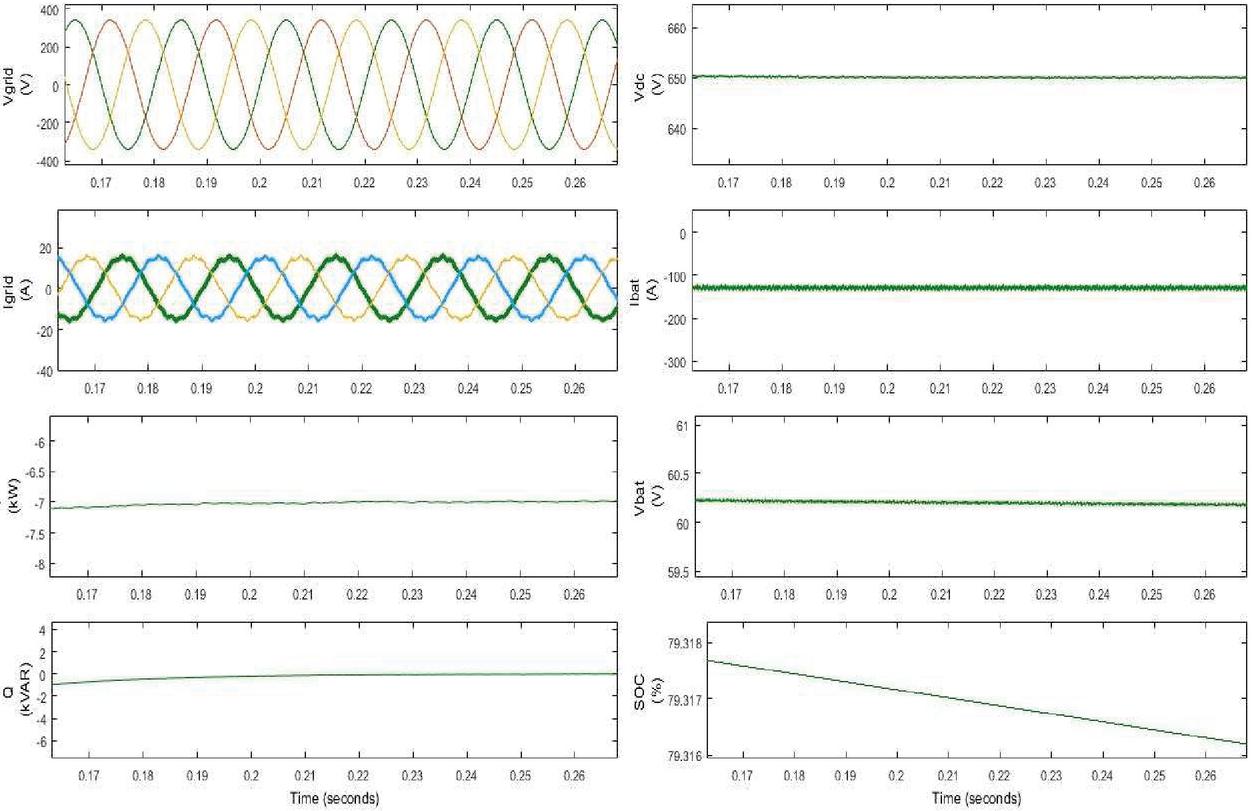
Figure 11 Performance during reverse power transfer (V2G) mode.
3 Conclusion
A three phase off board charger for electric vehicle is proposed which has a front end ac-dc converter and a back end dc-dc converter connected via a dc link. The proposed charger is bidirectional in nature which means it is able to transfer power to the grid using the stored energy of the battery thus paving way to vehicle to grid (V2G) technology which is an important aspect seeing the increase in the penetration of electric vehicles nowadays. The control algorithm for ac-dc converter was able to maintain the dc link voltage at the desired value with unity power factor at the input side. This control strategy allowed the independent control of active and reactive powers thus leading to a better performance of the proposed system. The methodology used for charging protects battery from over-voltages thus safeguarding the battery which is usually neglected in conventional chargers. The proposed charger is able to charge the lithium ion battery quickly and safely. The results obtained validate the proposed design and control strategy devised for the electric vehicles. Moreover, the load demand of grid can be decreased by feeding power back from V2G during peak hours. Further, the controlled charging reduces the stability issues of the grid.
References
[1] Farhad Ilahi Bakhsh, and Mohammad Saad Alam, “Comparative Study of Alternative Energy Vehicles: State of the art Review,” Power, Instrumentation & Energy Conference, AMU Aligarh, India, 12–13 Feb., 2011.
[2] Hamed Ahmadi-Nezamabad, Mohammad Zand, Araz Alizadeh, Mahdi Vosoogh, and Sayyad Nojavan, “Multi-objective optimization based robust scheduling of electric vehicles aggregator,” Sustainable Cities and Society, Volume 47, 2019, 101494, ISSN 2210-6707, doi.org/10.1016/j.scs.2019.101494.
[3] Mojtaba Ghasemi, Ebrahim Akbari, Mohammad Zand, Morteza Hadipour, Sahand Ghavidel and Li Li, “ An Efficient Modified HPSO-TVAC-Based Dynamic Economic Dispatch of Generating Units,” Electric Power Components and Systems, 47:19–20, 18261840, DOI: 10.1080/15325008.2020.1731876.
[4] Azimi Nasab M, Zand M, Eskandari M, Sanjeevikumar P, and Siano P, “Optimal Planning of Electrical Appliance of Residential Units in a Smart Home Network Using Cloud Services,” Smart Cities. 2021; 4(3):1173–1195. doi.org/10.3390/smartcities4030063.
[5] Azimi Nasab M, Zand M, Padmanaban S, Dragicevic T, and Khan B, “Simultaneous Long-Term Planning of Flexible Electric Vehicle Photovoltaic Charging Stations in Terms of Load Response and Technical and Economic Indicators. World Electric Vehicle Journal,” 2021; 12(4):190. doi.org/10.3390/wevj12040190.
[6] Venkatesh Boddapati and S. Arul Daniel, “Design and Feasibility Analysis of Hybrid Energy-Based Electric Vehicle Charging Station,” Distributed Generation & Alternative Energy Journal, Vol. 37_1, 41–72, 2021, DOI: 10.13052/dgaej2156-3306.3713.
[7] Kuditi Kamalapathi, Ponugothu Srinivasa, Rao Nayak and Vipul Kumar Tyagi, “Analysis of Dual Input Buck-Boost Converter for Solar PV Integration with Wireless Electric Vehicle Charger,” Distributed Generation & Alternative Energy Journal, Vol. 37_1, 73–102, 2021, DOI: 10.13052/dgaej2156-3306.3714.
[8] Salman Habib and et al., “Assessments of electric vehicles concerning impacts, charging infrastructure, with unidirectional and bidirectional chargers, and power flow comparisons,” International Journal of Energy Research, 2017, DOI: 10.1002/er.4033.
[9] Sujitha Nachinarkiniyan, Krithiga Subramanian, “Off-board electric vehicle battery charger using PV array,” IET Electrical Systems in Transportation, 2020, DOI: 10.1049/iet-est.2019.0035.
[10] Ujjwal Kumar Kalla and Tanmay Shukla, “State of Art and Comprehensive Study on Charging Systems for Electric Vehicles,” 2021 International Conference on Sustainable Energy and Future Electric Transportation (SEFET) IEEE, DOI: 10.1109/SeFet48154.2021.9375708.
[11] Shiyang Yang, He Chan, Dongsheng Yu and Jin huang, “An Integrated Multifunctional Battery Charger with Three-phase Charging for Plug-in Electric Vehicles,” IEEE 9th International Power Electronics and Motion Control Conference (IPEMC2020-ECCE Asia), DOI: 10.1109/IPEMC-ECCEAsia48364.2020.9367757.
[12] Sadeq Ali Qasem Mohammed and Jin-Woo Jung, “A Comprehensive State-of-the-Art Review of Wired/Wireless Charging Technologies for Battery Electric Vehicles: Classification/Common Topologies/Future Research Issues,” IEEE Access 2021, DOI: 10.1109/ACCESS.2021.3055027
[13] X. Lu, K. L. V. Iyer, K. Mukherjee and N. C. Kar, “A Dual Purpose Triangular Neural Network Based Module for Monitoring and Protection in Bi-Directional Off-Board Level-3 Charging of EV/PHEV,” IEEE Trans. on Smart Grid, vol. 3, no. 4, pp. 1670–1678, Dec. 2012, DOI: 10.1109/TSG.2012.2205950.
[14] Yang Xuan, Xu Yang, Wenjie Chen, Tao Liu, and Xiang Hao, “A Novel Three Level CLLC Resonant DC-DC Converter for Bidirectional EV Charger in DC Microgrids,” IEEE Transactions on Industrial Electronics, 0278-0046, 2019.
[15] Anjeet Verma and Bhim Singh, “Three-Phase Off-Board Bi-directional Charger for EV with V2G Functionality,” 2017 7th International Conference on Power Systems (ICPS), College of Engineering Pune, India. Dec 21–23, 2017, 978-1-5386-1789-2/17 © 2017 IEEE.
[16] M. Yilmaz, and P. T. Krein, “Review of battery charger topologies, charging power levels, and infrastructure for plug-in electric and hybrid vehicles,” IEEE Trans. Power Electronics., vol. 28, no. 5, pp. 2151–2169, May 2013, DOI: 10.1109/TPEL.2012.2212917.
[17] Rajesh Kumar Lenka, Anup Kumar Panda, Ashish Ranjan Dash, Venkataramana Naik N and Nishit Tiwary, “Reactive Power Compensation using Vehicle-to- Grid enabled Bidirectional Off-Board EV Battery Charger,” 2021 1st International Conference on Power Electronics and Energy (ICPEE), IEEE DOI: 10.1109/ICPEE50452.2021.9358582.
[18] J. S. Siva Prasad, Tushar Bhavsar, Rajesh Ghosh and G. Narayan, “Vector Control of three-phase AC/DC front-end converter,” Sadhana Vol. 33, Part 5, October 2008, pp. 591–613.
[19] Saran Chaurasiya and Bhim Singh, “A G2V/V2G Off-Board Fast Charger for Charging of Lithium-ion Based Electric Vehicles,” 2019 IEEE International Conference on Environment and Electrical Engineering, 978-1-7281-0653-3/19 © 2019 IEEE.
Biographies

Uzma Dar has received her B.Tech degree in Electrical Engineering from National Institute of Technology, Srinagar, India in the year 2018. And then pursued her M.Tech in Electrical Power Systems and Management from Jamia Millia Islamia, New Delhi, India and received her degree in 2021.

Anwar Shahzad Siddiqui is currently working as Professor, Electrical Engineering at Jamia Millia Islamia (Central University), New Delhi. He obtained his B.Sc Engg. (Electrical Engineering) and M.Sc Engg. (Power Systems and Electrical Drives) degrees from AMU, Aligarh both with Honors in 1992 and 1994 respectively. He has been teaching and guiding research for about twenty five years at JMI, New Delhi. Before joining Jamia, he was a faculty at Department of Electrical Engineering, AMU, Aligarh. He served at BITS, Pilani-Dubai campus from 2003–2008 as an Associate Professor of Electrical and Electronics Engineering and Registrar. His research interests include Power System control and management. He has applied many Artificial Intelligence Techniques in the field of Electrical Power System. He has more than 150 research papers published in refereed international and national journals and conferences of repute having more than 630 citations with h-index 14 and i10-index-21.

Farhad Ilahi Bakhsh received Diploma and B. Tech degree in Electrical Engineering from Aligarh Muslim University (AMU), Aligarh, India in 2006 and 2010, respectively. He was awarded University Medal (Gold) for standing first throughout Diploma in Electrical Engineering. He has been awarded first position in SPOTLIGHT and third position in overall solar conference during cognizance 2010 in Indian Institute of Technology, Roorkee. Then he pursued Masters in Power System and Drives from the Aligarh Muslim University. In Masters he secured first position in his branch. He joined IEEE during Masters and since then he is an IEEE member.
He also worked as head of Research & Development cell, IEEE student chapter, AMU for around two years. Under this cell, he developed five new systems i.e. A rotor power control based flexible asynchronous AC link (FASAL) system, A miss-call based switching system for multiple loads or appliances, A power controller circuit based flexible asynchronous AC link (FASAL) system for induction generator applications, A combined voltage control and rotor power control based flexible asynchronous AC link (FASAL) system and A waste fluid pressure based energy generation system. Among these five systems, four systems have been published by an official Journal of Patent Office.
Then he pursued Ph.D. from Indian Institute of Technology Roorkee, India. During his Ph.D. he developed a new method for grid integration for wind energy generation system which has been recognized worldwide. He served as Assistant Professor in Department of Electrical & Renewable Energy Engineering, School of Engineering & Technology, Baba Ghulam Shah Badshah University, Rajouri, J & K, India. He also worked as Coordinator of Massive Open Online Courses (MOOC’s) under SWAYAM platform in Baba Ghulam Shah Badshah University and Co-ordinator of NBA, School of Engineering & Technology, Baba Ghulam Shah Badshah University. He developed an automatic solar tracking system which has been appreciated by IEEE India Council, Centre for Embedded Product Design, Centre for Electronics Design and Technology, Netaji Subhas Institute of Technology in association with IEEE Delhi Section & IEEE CAS, Bangalore Chapter. Currently he is serving as Assistant Professor in Department of Electrical Engineering, National Institute of Technology Srinagar, Jammu & Kashmir, India. Here, he is having many Departmental and Institutional responsibilities. He started IEEE Student Branch in NIT Srinagar and since then he is serving as Counselor of it.
Recently, he has won “10 for 10 Typhoon HIL Award” from Switzerland, Europe. He delivered a number of Keynote talks, Invited talks and Expert Lectures at National and International level in conferences, workshops, STC, etc. He have more than 50 published papers in International reputed Journals, International reputed Conferences and National Conferences. Many times, he got best paper awards in International conferences. Moreover, he have four published patents and one granted patent in his credit. His research area of interests includes Application of Variable Frequency Transformer, Renewable Energy Systems (Solar & Wind), Drives and Alternate Energy Vehicles.
Distributed Generation & Alternative Energy Journal, Vol. 37_4, 959–978.
doi: 10.13052/dgaej2156-3306.3744
© 2022 River Publishers