Design and Implementation of Different Drive Topologies for Control of Induction Motor for Electric Vehicle Application
Mohammed Aslam Husain1,*, Ritik Rajput1, Maneesh Kumar Gupta1, Md Tabrez2, Md Waseem Ahmad3 and Farhad Ilahi Bakhsh4
1Department of Electrical Engineering, REC Ambedkar Nagar, India
2Department of Electrical & Electronics Engineering, Motihari College of Engineering, India
3Department of Electrical and Electronics Engineering, National Institute of Technology Karnataka, Surathkal, India
4Department of Electrical Engg., Hazratbal, National Institute of Technology Srinagar, India
E-mail: mahusain87@gmail.com
*Corresponding Author
Received 27 October 2021; Accepted 20 December 2021; Publication 22 April 2022
Abstract
To improve driving range in Electric vehicles (EV), parallel-series connection of battery cells is a necessity. Supressing the circulating current in the battery board of parallel connected battery strings helps improve the lifespan of the batteries. This study presents a comparison of the requirements of parallel strings of batteries in three different popular topologies for open end winding induction motor (IM) drives in EV. The topologies analyzed are a 3-phase voltage source inverter (VSI), a Dual fed inverter and three single-phase H-Bridge VSIs. These converters are modulated using Space vector pulse width modulation (SVPWM) as it has better performance compared to Sine PWM. MATLAB-Simulink models are developed for the converter topologies. The simulation results show that the three single-phase inverter topology feeding the drive is the best alternative when compared on the basis of battery requirement and switch loss. Moreover, each H-bridge inverter (in the three single-phase inverter topology) can be used as charger and the problem of circulating current during charging will also be least as compared to other schemes.
Keywords: Electric vehicle, open end winding induction motor drives, batteries, voltage source inverters, pulse width modulation.
1 Introduction
Inverter nowadays has taken a remarkable place in the Electrical vehicle industry. Different types of inverter are being employed for charging the batteries [1, 2]. In the present world, Electric Vehicles (EVs) are well known to be friendly to the environment as compared to the standard internal combustion (IC) machines. EV’s has been rising normally since the most recent two decades [1–4]. The ordinary EV comprises the batteries, inverter, and motors for traction. Batteries work as the source of energy and the inverter is used to drive and control the EV’s AC motor.
The proper operation and effectiveness of EV’s mainly depend on the type of inverter used, its control strategy, and the storage system interfacing. To regulate the energy delivery from storage system to the motor used in EV, an efficient inverter is required. The converters and controllers used in EV’s have a large number of components, the current stress is also high, the dynamic response is also slow, switching losses are high and overall complex computation is there. The use of multilevel inverters in EV’s presents low switching losses and low total harmonic distortion, however there is an unbalanced capacitor voltage across two dc-links. The generation of common-mode voltage (CMV) is one of the main drawback of using PWM inverters, because this voltage develops common-mode current that flows through the stator windings. This CMV also give rise to leakage current and degrades the bearings due to rise in bearing currents [5]. Open-end winding induction motor drive has the ability to eliminate CMV using proper controlling.
The Electric Vehicle industry generally uses DC motors and induction motor, but many of them are using Induction motor (IM) because it is more robust and economical [5, 6]. Healthy and high-density batteries are needed to achieve long driving in EV. The energy concentration of the battery is a big concern in the case of EVs [7–12]. Lithium-ion batteries with high energy intensity and long life are broadly accepted in EVs. IM with more power rating and low voltage rating requires more batteries arranged in series and parallel order [13]. In this type of battery arrangement, it is quite difficult to maintain the same voltage across battery terminals. If the voltage between parallelly connected batteries is unequal, then it gives rise to the flow of the circulating current between them, which may damage the batteries and would also break down the safety and durability of the system. To solve this problem battery management system (BMS) and battery equalizer is used, however, this raises the price of EV and makes the vehicle more uneconomical [14, 15]. Furthermore, this may put additional load for up-keeping BMS in the situation of a letdown. To look into the above problem, three different types of topology have been covered in this article. This study presents a comparison of 3 different three-phase inverter (TPI) topologies used in SVPWM modulated induction motor (IM) drives. The topologies analyzed are a 3-Phase VSI, Dual fed inverter (DFI) and three single-phase H-Bridge (SPHB) VSIs for open-end winding induction motor (OEWIM) drive. The assessment concerning these topologies is done on the basis of the battery required in parallel.
2 PWM Invertes for IM Drives
In a Power Electronic Circuit, Pulse Width Modulation (PWM) based inverters are mostly used in important practical based applications [16–18]. PWM inverters generate the alternating voltages of adjustable frequency and magnitude and thus help in achieving the wide speed variation of the EV [19–23].
The Space Vector PWM (SVPWM) is an improved PWM technique, which was brought forward specifically for the AC motors speed regulation and for varying frequencies in 1980. The inverters are used for controlling the output to get a proper voltage waveform. Sinusoidal PWM (SPWM) is used to control and maintain the drive’s performance throughout the operating range from zero to 78 percent of the value that would be reached by square wave operation of the inverter. The linear correlation of modulation index (MI) and the output voltage is not sustained when the MI exceeds this value and requires the over modulation method. On the other hand, SVPWM based techniques have been as often as possible utilized, on the grounds that they decrease commutation losses, output voltage harmonic contents, and increase amplitude MI as compared to conventional SPWM strategies. In addition, SVPWM methods are easily used and their implementation in processors is also easy. Space-Vector modulation (SVM) was initially evolved as a vector way to deal with PWM-based for TPIs [21, 24–26].
SVPWM technique works in a plane that is partitioned into six areas detached by the switching state vectors (SSV) The space vector PWM method works in a plane which is distributed in to six sectors of 60 each. Each sector is separated by eight switching state vectors [27, 28]. SSV is the mix of switches (conducting or non-conducting) in the inverter’s layout. Plane reference voltage (vector), V is utilized to identify two adjoining SSV (V1 and V2 in the principal part) and to ascertain the switching time interval (T1 and T2 separately) against which everyone is active. At the inspecting time T0 (Tz T1 T2), vectors at zero-state (associating the entirety of three-phase windings to the negative or positive dc bus bar) are dynamic. Tz is the total cycle period. The detailed explanation of SCPWM can be seen in [27, 28].
SVPWM uses voltage vector which is very near to the value of reference circle as compared to other switching methods of inverter. Figure 1 shows the exemplary graph of a three-stage VSI fed IM drive model [29]. In TPI circuit, each phase are characterized as a switch S. S1, S2, S3, S4, S5, and S6 are the six switches, and an, a’, b, b’, c and c’ are the exchanging variable that will be molding the output voltage waveform. Exactly when an upper switch is turned OFF, i.e., when a, b or c is 0, the comparing lower switch is turned ON (i.e., the relating a’, b’ or c’ is 1), So the ON and OFF states of the upper switches S1, S3 and S5 can be used to choose the output voltage.
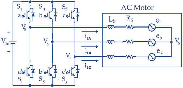
Figure 1 3-phase VSI fed IM drive model.
The switching variable vector and the line-to-line voltage vector are related, The relationship is given:
| (1) |
The switching variable vector and the phase voltage vector are also related. The relationship is given:
| (2) |
As appeared in Figure 1, every single switch having two state ON and OFF so feasible combination for three upper switches is eight (2) and the ON/OFF conditions of lower switches are inverse to the upper ones as are suitably decided after the condition of the upper switches are resolved [30, 31].
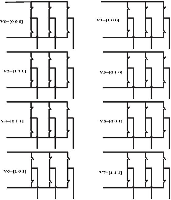
Figure 2 Eight voltage vectors (V0 to V7) of inverter.
From the conditions, the eight yield exchanging vectors, line to neutral voltage (output phase.voltage), and line-to-line voltage as far as DC-link voltage Vdc, are appeared in Table 1. This. shows the most reachable voltage given a DC bus voltage of Vdc and Figure 2 shows the 8 voltage vectors (V0 to V7) of inverter.
Table 1 Line to neutral voltage (output phase voltage), and line to line voltage in terms of DC-link V
| Switching | Output Phase | Line to Line | |||||||
| Voltage | Patterns | Voltage | Voltage | ||||||
| V | Sa | Sb | Sc | Van | Vbn | Vcn | Vab | Vbc | Vca |
| V0 | 0 | 0 | 0 | 0 | 0 | 0 | 0 | 0 | 0 |
| V1 | 1 | 0 | 0 | 2/3 | 1/3 | 1/3 | 1 | 0 | 1 |
| V2 | 1 | 0 | 0 | 1/3 | 1/3 | 2/3 | 0 | 1 | 1 |
| V3 | 0 | 1 | 0 | 1/3 | 2/3 | 1/3 | 1 | 1 | 0 |
| V4 | 0 | 1 | 1 | 2/3 | 1/3 | 1/3 | 1 | 0 | 1 |
| V5 | 0 | 1 | 1 | 1/3 | 1/3 | 2/3 | 0 | 1 | 1 |
| V6 | 0 | 0 | 1 | 1/3 | 2/3 | 1/3 | 1 | 1 | 0 |
| V7 | 1 | 0 | 1 | 0 | 0 | 0 | 0 | 0 | 0 |
3 Analysis of Inverter Topologies for IM Drive
In this section three different TPI topologies are used in IM drive which are based on SVPWM have. been studied. 3-Phase VSI fed IM, DFI for OEWIM and 3 SPHB. Inverters fed OEWIM is analyzed in this section. The study is mainly focused on the use of the number of batteries in parallel and thus circulating current generation. It is assumed that in each topology the input power of the induction motor is constant and has a value of 4.224 kW.
3.1 3-Phase VSI Fed IM
In this sub-section a 3-phase voltage source inverter (VSI) fed induction motor drive topology based on SVPWM has been studied [32, 33]. Figure 3(a) shows power circuit for a 3-phase VSI. The DC voltage is been supplied by a battery pack shown in Figure 3(b).
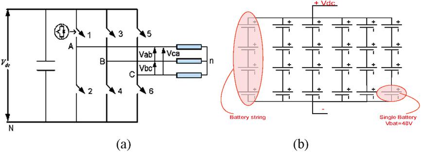
Figure 3 Three-Phase VSI and (b) Battery combination in a pack.
Each leg of inverter has two back to back-linked semiconductor devices. One is used as a manageable device and other one is a diode for protection. Table 2 summarizes the grouping of batteries essential for conventional 3-phase VSI. It can be observed that for the 48V battery, this inverter topology uses four 48V batteries which are linked in series (to make a string) & six strings are parallelly linked as shown in the Figure 3(b).
Table 2 gives three types of battery profiles, for the same load demand each battery’s current profile also changes. And, for the same load demand, we can calculate the power for each profile as:
| (3) |
Table 2 Required figure of batteries in conventional 3-phase VSI
| Battery | Total | Quantity of | Quantity of | Current |
| Profiles | Quantity of | Batteries in | Strings in | Flow From |
| (Voltage) | Batteries | a String | Parallel | Battery Pack |
| 48 | 24 | 4 | 6 | 88 |
| 24 | 24 | 2 | 12 | 176 |
| 12 | 24 | 1 | 24 | 352 |
Equation (3) gives the total load demand on the battery bank by the induction motor. For the comparative analysis, this value of load is taken to be same for all the discussed topologies. In this topology, a single inverter is used and thus the total load is mounted on this inverter.
The variation in the quantity of batteries strings in parallel w.r.t. battery pack voltage and current flow from battery pack are shown in Figure 4.

Figure 4 Variation in quantity of batteries strings in parallel.
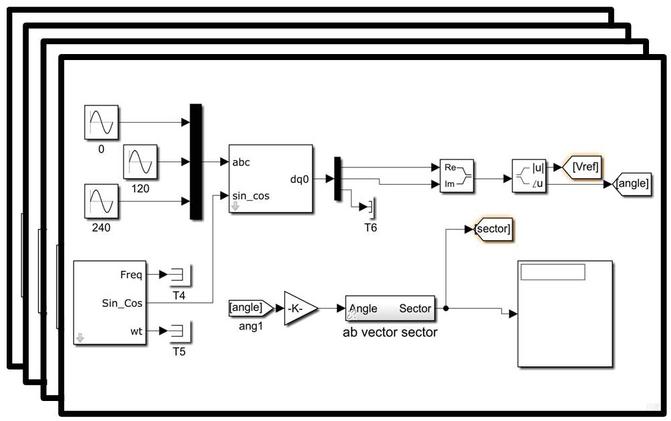
Figure 5(a): Simulink model of the 3-phase to d-q axis block.
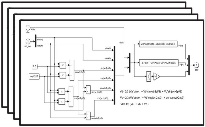
Figure 5(b): Simulink model of the 3-phase to d-q axis block.
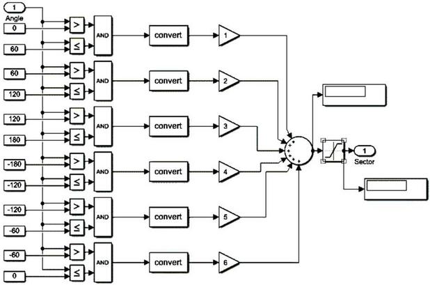
Figure 6 Sector selection block.
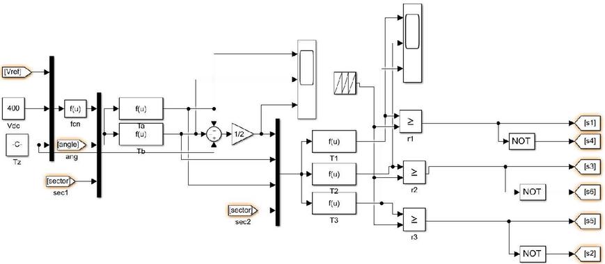
Figure 7 Switching pulse generation block.
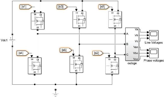
Figure 8 Simulink Model of 3-phase VSI.
Figures 5(a) and 5(b) displays the Simulink model of the 3-phase to d-q axis block and Sub-system of d-q axis conversion block respectively. The parameters of the system are initialized and Simulink model in build using the 3-phse to d-q axis conversion. There are 6 sectors. Every sector comprises angle of 60 degree. The Sector Selection Block is shown in Figure 6. In this topology there are six switches, so for the triggering we need six switching pulses. The Switching Pulse Generation Block is shown in Figure 7. The complete Simulink model of 3-phase VSI is displayed in Figure 8.
Figures 9(a) and 9(b) show the results obtained using the model of Figure 8. The output voltage waveform is unfiltered and seems like a three-phase ac source.
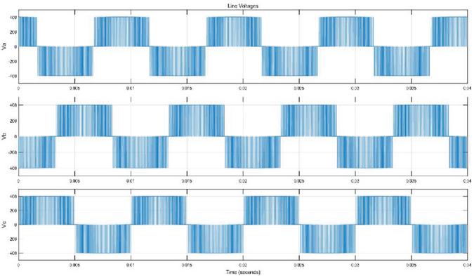
Figure 9(a): Unfiltered Line Voltage of 3-phase VSI.
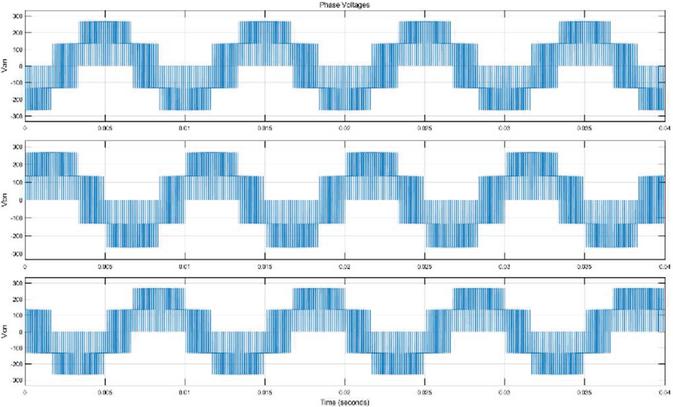
Figure 9(b): Unfiltered Phase Voltage of 3-phase VSI.
3.2 Dual Fed Inverter for OEWIM Drive
This is the second kind of topology introduced in this article where a 3-phase IM with OEWs and two isolated dc sources are utilized. This topology has a few points of interest in engine drive applications [34–37]:
• It assists with decreasing the voltage blocking prerequisites for some of the power semiconductor switches.
• Both utilized inverters should part switching actions prompting lower device specific commutation frequencies.
• It assists with improving the accessibility since fault tolerance can be presented.
• For a particular quality of output waveform, it assists with lowering the switching losses.
Double inverter schemes have been investigated in several papers for various applications. This topology likewise utilizes isolation transformer whose size can be decreased at the cost of lowered MI [38]. The power circuit scheme of a DFI is appeared in Figure 10(a).
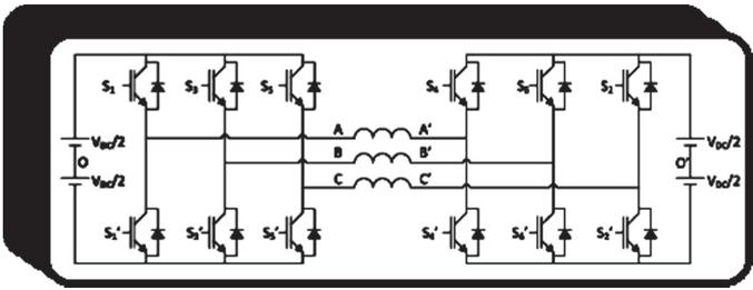
Figure 10(a): DFI for OEWIM.
Table 3 summarizes the combination of batteries required for DFI. It can be observed for 48V battery, each inverter uses a combination of three parallel string and each string having four 48V batteries as shown in Figure 10(b).
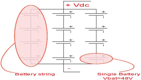
Figure 10(b): Battery combination in a pack used in Figure 10(a).
Table 3 Number of batteries required using DFI
| Battery | Current | Total | Quantity of | Quantity of |
| Profiles | Flow From | Quantity of | Batteries in | Strings in |
| (Voltage) | Battery Pack | Batteries | a String | Parallel |
| 48 | 44 | 12 | 4 | 3 |
| 24 | 88 | 12 | 2 | 6 |
| 12 | 176 | 12 | 1 | 12 |
In this topology, two inverters are used so the total input power is shared between two inverters. So, the per inverter input power is 2112 W i.e.
| Total Input Power Demand | |
| Per Inverter Input Power |
This shows that the load demand of per inverter is half form the conventional method and thus, gives low stress on the switches of the inverter. Also, by comparing Tables 2 and 3, It is clear to see that the number of battery strings in parallel is less in case of DFI for OEWIM.
The complete Simulink model of DFI for OEWIM is shown in Figure 11. Results obtained using this model is similar to that obtained using 3-phase VSI and are shown in Figures 9(a) and 9(b). The waveform of output voltage is unfiltered and seems like a three phase ac source.
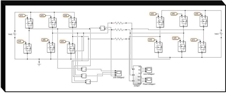
Figure 11 Simulink model of DFI for OEWIM.
3.3 3 SPHB Inverters fed OEWIM Drive
In this section, three SPHB-VSIs fed an induction motor with OEWIM drive is dealt with. Every phase in OEWIM is fed by separate SPHB-VSI. Hence, each SPHB voltage source.inverter needs an individual DC supply [39, 40]. The low voltage profile type batteries are generally used for a decrease in price and weight. The configuration upsurges the reliability as it needs fewer cells arranged in series as well as parallel [41]. Figure 12(a) shows the power circuit topology of a three single-phase inverter. Table 4 summarizes the combination of batteries required for this scheme. It can be observed for 48V battery, each inverter uses a combination of two parallel string and each string having four 48V batteries as shown in Figure 12(a). In this topology, three inverters have been used, so the overall input power is divided into the 3 SPHB VSIs and hence, the per inverter input.power value is 1408 W i.e.
| Total Input Power Demand | |
| Per Inverter Input Power |
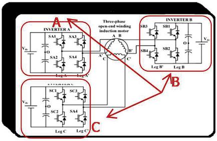
Figure 12(a): 3 SPHB inverters fed an OEWIM.
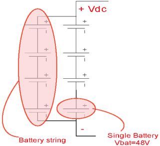
Figure 12(b): Battery combination in a pack used in Figure 12(a).
Table 4 Total batteries required utilizing 3 SPHB VSIs fed OEWIM
| Battery | Current | Total | Quantity | Quantity of |
| Profiles | Flow From | Quantity of | of Batteries | Strings in |
| (Voltage) | Battery Pack | Batteries | in a String | Parallel |
| 48 | 30 | 8 | 4 | 2 |
| 24 | 58 | 8 | 2 | 4 |
| 12 | 117 | 8 | 1 | 8 |
This shows that the load demand of per inverter is one third as that in the conventional method and thus this gives very low stress on the switches of the inverter. Also by comparing Tables 2, 3 and 4, it can be seen that the quantity of battery strings in parallel is the least on account of 3 SPHB VSIs fed OEWIM drive.
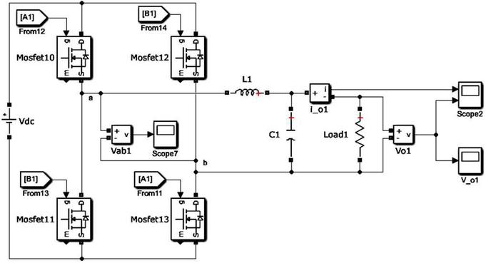
Figure 13 Per phase Simulink model of 3-SPHB inverters fed OEWIM drive.
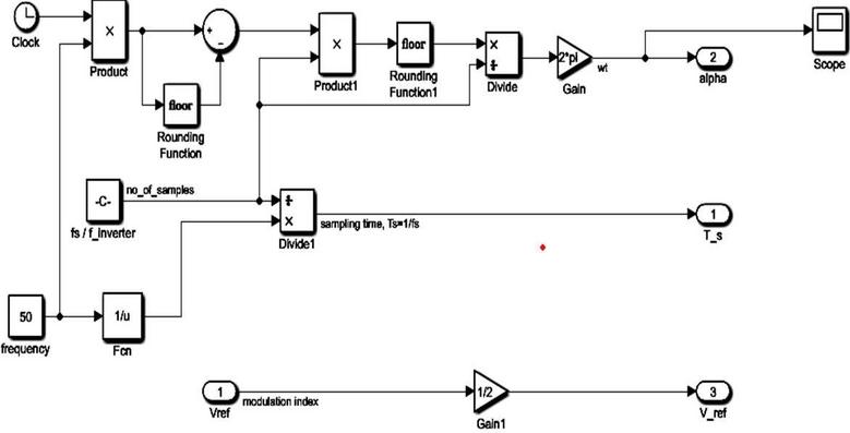
Figure 14(a): Angle calculation block.
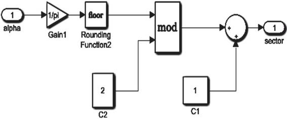
Figure 14(b): Sector selection block.
The per-phase Simulink model of 3 SPHB-VSIs fed OEWIM drive is presented in Figure 13. Three such inverter arrangements like this are used and connected as shown in Figure 12(a) with 120-degree phase shift. Figures 14(a) and 14(b) shows the block used for the purpose of angle calculation and the sector selection block respectively. Figures 15(a) and 15(b) shows the switching pulse generation block and Subsystem of Switching Pulse Generation Block respectively. Results obtained using this model is displayed in Figures 16(a) and 16(b). The waveform of output voltage is filtered and seems like a three-phase ac source. The phase current in each phase of OEWIM for two different loads is shown in Figures 17 and 18 respectively. The switching pulses is shown in Figure 19.
Figure 15(a): Switching pulse generation block.
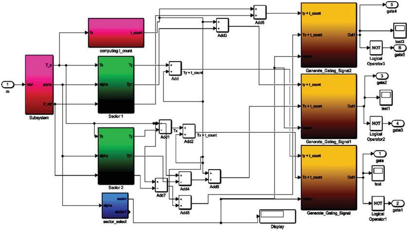
Figure 15(b): Sub system of switching pulse generation block.
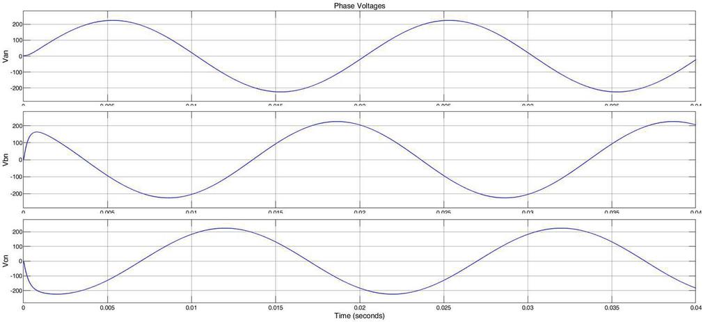
Figure 16(a): Filtered phase voltage.
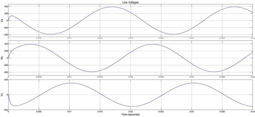
Figure 16(b): Filtered line voltage.
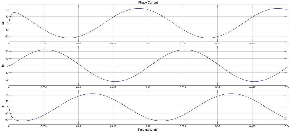
Figure 17 Phase current in each phase of OEWIM working at rated load.
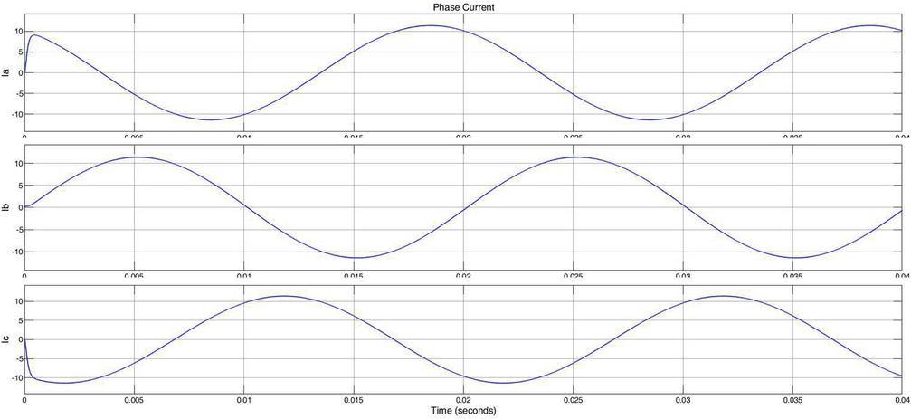
Figure 18 Phase current in each phase of OEWIM working at half value of rated load.
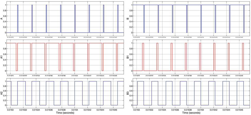
Figure 19 Switching pulses used in DFI for OEWIM as shown in Figure 11.
4 Discussion
In this section all the three topologies of the inverter viz. 3-Phase VSI, DFI and 3 single-phase H-Bridge are compared. Table 5 is about the comparison of different parameters while Table 6 presents the comparison of the battery requirements in the three different schemes discussed in this paper. Figures 20, 21 and 22 represents the required quantity of different rating batteries in different inverter topologies. It is clear that the number of strings in the case of three shingle phase inverters is less as compared to other schemes, and thus the circulating current will also be least. Low circulating current will result in higher battery life and better performance. The stress on switches is also low in case of 3-SPHB scheme as compared to 3-Phase VSI. Fault tolerance is also high in case of 3-SPHB scheme, as in case of fault in one leg, other two legs can work but at a reduced capacity. Moreover, each SPHB inverter can be employed as charger and thus is an added advantage of this scheme. In this scheme (three SPHB), even during the charging, the problem of circulating current will be least as compared to other schemes. The problem of circulating current during charging will be more for the cases having more number of stings of batteries in parallel, this is due to the difference in batteries internal resistances. However, if the number of parallel stings is low, there will be low circulating current and hence the value of circulating current is very low in case of three SPHB topology as compared with other schemes.
Table 5 Comparison of discussed three different inverter topologies
| Parameters of Comparison | 3-Phase VSI | DFI | 3-SPHB |
| Input power | 4.22 KW | 4.22 KW | 4.22 KW |
| Number of Switches | 6 | 12 | 12 |
| Stress on switches | High | Low | Low |
| Switching losses | Low | High | High |
| Fault tolerance | Low | High | High |
| Power shared by each inverter unit | Full | Half | One third |
| Life span of batteries | Short | Moderate | Longest |
Table 6 Required quantity of batteries in the discussed schemes
| Battery | Current Drawn | Total No. of | No. of Batteries | No. of Battery | |
| Inverter | Pack | From | Batteries | in | Strings in |
| Scheme | Voltage | Battery Pack | Per Inverter | Series | Parallel |
| Three single-phase | 12 | 117 | 8 | 1 | 8 |
| H-Bridge inverters | 24 | 58 | 8 | 2 | 4 |
| 48 | 30 | 8 | 4 | 2 | |
| Dual fed | 12 | 176 | 12 | 1 | 12 |
| inverter | 24 | 88 | 12 | 2 | 6 |
| 48 | 44 | 12 | 4 | 3 | |
| Conventional | 12 | 352 | 24 | 1 | 24 |
| three-phase | 24 | 176 | 24 | 2 | 12 |
| inverter | 48 | 88 | 24 | 4 | 6 |
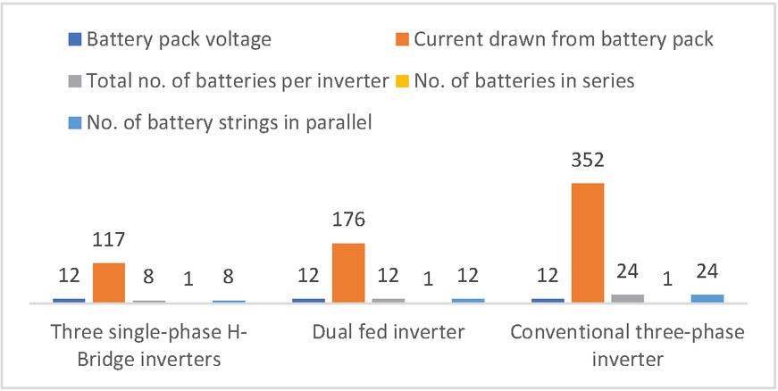
Figure 20 Required quantity of 12V batteries in different inverter topologies.
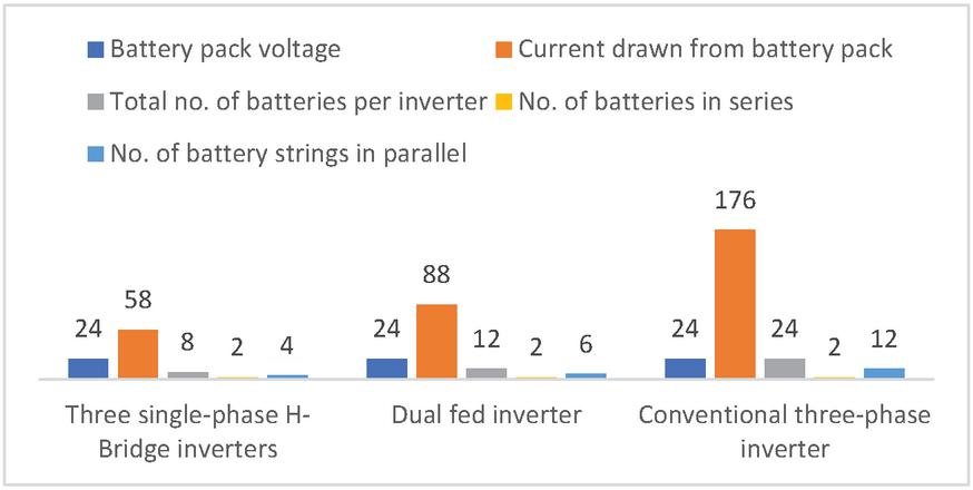
Figure 21 Required quantity of 24V batteries in different inverter topologies.
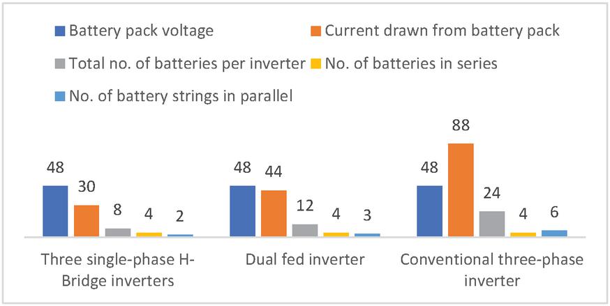
Figure 22 Required quantity of 48V batteries in different inverter topologies.
5 Conclusion
This paper analyses the performance of different VSI topologies for IM drives in EV for minimizing the circulating current among the parallelly connected battery in the DC-link. Simulink model is developed for 3-Phase voltage source inverter (VSI), DFI and 3 SPHB-VSIs. To decrease the quantity of parallelly linked batteries, an optimal selection method has been outlined. The simulation result shows that the three single-phase inverter topology utilizes fewer batteries coupled in parallel for a given power rating of inverter. Such topology would minimize loss and stress on switches of the inverter.
References
[1] M. D. Siddique et al., “Asymmetrical Multilevel Inverter Topology with Reduced Number of Components,” Jul. 2018, doi: 10.1109/PEDES.2018.8707663.
[2] M. D. Siddique and A. Riyaz, “Single-Phase 9L Switched-Capacitor Boost Multilevel Inverter (9L-SC-BMLI) Topology,” pp. 13–17, 2020.
[3] S. Langsdorf, “EU Energy Policy: From the ECSC to the Energy Roadmap 2050,” 2011.
[4] J. R. Hickman, “EVs: the here and now,” Renew. Energy Focus, vol. 10, no. 3, pp. 28–30, May 2009, doi: 10.1016/S1755-0084(09)70117-6.
[5] M. J. Akhtar and R. K. Behera, “Space Vector Modulation for Distributed Inverter-Fed Induction Motor Drive for Electric Vehicle Application,” IEEE J. Emerg. Sel. Top. Power Electron., vol. 9, no. 1, pp. 379–389, Jan. 2020, doi: 10.1109/jestpe.2020.2968942.
[6] W. Leonhard, “Symmetrical Three—Phase AC Machines,” 2001, pp. 163–214.
[7] K. Morrow, D. Karner, and J. Francfort, “Plug-in Hybrid Electric Vehicle Charging Infrastructure Review Final Report Battelle Energy Alliance Contract No. 58517,” 2008. Accessed: Feb. 14, 2021. [Online]. Available: http:avt.inel.gov/pdf/phev/phevinfrastructureReport08.pdf.
[8] K. Rajashekara, “Present status and future trends in electric vehicle propulsion technologies,” IEEE J. Emerg. Sel. Top. Power Electron., vol. 1, no. 1, pp. 3–10, 2013, doi: 10.1109/JESTPE.2013.2259614.
[9] A. Latif, A. Pramanik, D. C. Das, I. Hussain, and S. Ranjan, “Plug in hybrid vehicle-wind-diesel autonomous hybrid power system: frequency control using FA and CSA optimized controller,” Int. J. Syst. Assur. Eng. Manag., vol. 9, no. 5, pp. 1147–1158, Oct. 2018, doi: 10.1007/s13198-018-0721-1.
[10] Y. Dashora, J. W. Barnes, R. S. Pillai, T. E. Combs, M. Hilliard, and M. S. Chinthavali, “The PHEV charging infrastructure planning (PCIP) problem,” Int. J. Emerg. Electr. Power Syst., vol. 11, no. 2, Jun. 2010, doi: 10.2202/1553-779X.2482.
[11] P. Jayal and G. Bhuvaneswari, “A novel space vector modulation-based transistor-clamped H bridge inverter-fed permanent magnet synchronous motor drive for electric vehicle applications,” Int. Trans. Electr. Energy Syst., vol. 31, no. 3, p. e12789, Mar. 2021, doi: 10.1002/2050-7038.12789.
[12] M. A. Husain, A. Jain, and A. Tariq, “A novel fast mutable duty (FMD) MPPT technique for solar PV system with reduced searching area,” J. Renew. Sustain. Energy, vol. 8, no. 5, 2016, doi: 10.1063/1.4963314.
[13] U. Pettersson, “Power industry needs to think smarter on electric cars: Part I - Renewable Energy Focus.” http://www.renewableenergyfocus.com/view/42367/power-industry-needs-to-think-smarter-on-electric-cars-part-i/ (accessed Feb. 14, 2021).
[14] K. W. E. Cheng, B. P. Divakar, H. Wu, K. Ding, and H. F. Ho, “Battery-management system (BMS) and SOC development for electrical vehicles,” IEEE Trans. Veh. Technol., vol. 60, no. 1, pp. 76–88, Jan. 2011, doi: 10.1109/TVT.2010.2089647.
[15] M. H. Shamsi, H. A. Khan, and M. A. Husain, Accurate Equivalent Circuit Model for Battery States Estimation, vol. 553. 2019.
[16] X. Wu, G. Tan, Z. Ye, Y. Liu, and S. Xu, “Optimized common-mode voltage reduction PWM for three-phase voltage-source inverters,” IEEE Trans. Power Electron., vol. 31, no. 4, pp. 2959–2969, Apr. 2016, doi: 10.1109/TPEL.2015.2451673.
[17] B. Tabbache, M. Benbouzid, A. Kheloui, J. M. Bourgeot, and A. Mamoune, “An improved fault-tolerant control scheme for PWM inverter-fed induction motor-based EVs,” ISA Trans., vol. 52, no. 6, pp. 862–869, Nov. 2013, doi: 10.1016/j.isatra.2013.07.004.
[18] A. Tariq, M. A. Husain, M. Ahmad, and M. Tariq, “Simulation and study of a grid connected multilevel converter (MLC) with varying DC input,” 2011 10th Int. Conf. Environ. Electr. Eng., no. Mlc, pp. 1–4, 2011, doi: 10.1109/EEEIC.2011.5874704.
[19] R. Nair, R. Mahalakshmi, and K. C. Sindhu Thampatty, “Performance of three phase 11-level inverter with reduced number of switches using different PWM techniques,” in Proceedings of IEEE International Conference on Technological Advancements in Power and Energy, TAP Energy 2015, Aug. 2015, pp. 375–380, doi: 10.1109/TAPENERGY.2015.7229648.
[20] M. S. A. Shaikh and R. Maurya, “A Comparative Study of PWM Techniques for Multiphase Induction Motor Drives,” Int. J. Emerg. Electr. Power Syst., vol. 19, no. 5, Oct. 2018, doi: 10.1515/ijeeps-2018-0049.
[21] E. Robles, M. Fernandez, J. Andreu, E. Ibarra, and U. Ugalde, “Advanced power inverter topologies and modulation techniques for common-mode voltage elimination in electric motor drive systems,” Renewable and Sustainable Energy Reviews, vol. 140. Elsevier Ltd, p. 110746, Apr. 01, 2021, doi: 10.1016/j.rser.2021.110746.
[22] F. Eroglu, M. Kurtoglu, and A. M. Vural, “Bidirectional DC–DC converter based multilevel battery storage systems for electric vehicle and large-scale grid applications: A critical review considering different topologies, state-of-charge balancing and future trends,” IET Renew. Power Gener., vol. 15, no. 5, pp. 915–938, Apr. 2021, doi: 10.1049/rpg2.12042.
[23] M. D. Siddique et al., “Single-Phase Boost Switched-Capacitor Based Multilevel Inverter Topology with Reduced Switching Devices,” vol. 6777, no. c, pp. 1–11, 2021, doi: 10.1109/JESTPE.2021.3129063.
[24] B. N. Ch.V. Chakravarthi, P. Naveen, S. Pragaspathy, and V. S. N. N. Raju, “Performance of Induction Motor with hybrid Multi level inverter for Electric vehicles,” in 2021 International Conference on Artificial Intelligence and Smart Systems (ICAIS), Mar. 2021, pp. 1474–1478, doi: 10.1109/ICAIS50930.2021.9395885.
[25] M. D. Siddique and S. Member, “Low Switching Frequency Based Asymmetrical Multilevel Inverter Topology With Reduced Switch Count,” IEEE Access, vol. 7, pp. 86374–86383, 2019, doi: 10.1109/ACCESS.2019.2925277.
[26] A. Iqbal, S. Member, and M. D. Siddique, “A New Eight Switch Seven Level Boost Active Neutral Point Clamped,” 2020, doi: 10.1109/ACCESS.2020.3036483.
[27] H. C. Skudelny and G. V. Stanke, “Analysis and Realization of a Pulsewidth Modulator Based on Voltage Space Vectors,” IEEE Trans. Ind. Appl., vol. 24, no. 1, pp. 142–150, 1988, doi: 10.1109/28.87265.
[28] J.-S. Kim and S.-K. Sul, “A Novel Voltage Modulation Technique of the Space Vector PWM.,” IEEJ Trans. Ind. Appl., vol. 116, no. 8, pp. 820–825, Jul. 1996, doi: 10.1541/ieejias.116.820.
[29] V. Blasko and V. Kaura, “A new mathematical model and control of a three-phase AC-DC voltage source converter,” IEEE Trans. Power Electron., vol. 12, no. 1, pp. 116–123, 1997, doi: 10.1109/63.554176.
[30] R. Wu, S. B. Dewan, and G. R. Slemon, “A PWM AC-to-DC Converter with Fixed Switching Frequency,” IEEE Trans. Ind. Appl., vol. 26, no. 5, pp. 880–885, 1990, doi: 10.1109/28.60060.
[31] R. Wu, S. B. Dewan, and G. R. Slemon, “Analysis of an AC-to-DC Voltage Source Converter Using PWM with Phase and Amplitude Control,” IEEE Trans. Ind. Appl., vol. 27, no. 2, pp. 355–364, 1991, doi: 10.1109/28.73626.
[32] H. Stemmler; P. Guggenbach, “Configurations of high-power voltage source inverter drives - IET Conference Publication,” Accessed: Feb. 14, 2021. [Online]. Available: https://ieeexplore.ieee.org/document/265146.
[33] J. H. Beigel et al., “Remdesivir for the Treatment of Covid-19—Preliminary Report,” N. Engl. J. Med., pp. 1–12, 2020, doi: 10.1056/nejmoa2007764.
[34] E. G. Shivakumar, K. Gopakumar, S. K. Sinha, A. Pittet, and V. T. Ranganathan, “Space vector PWM control of dual inverter fed open-end winding induction motor drive,” in Conference Proceedings – IEEE Applied Power Electronics Conference and Exposition – APEC, 2001, vol. 1, pp. 399–405, doi: 10.1109/apec.2001.911678.
[35] S. M. W. Ahmed, M. M. Eisa, G. M. A. Sowilam, and A. B. S. M. Salem, “Open ends induction motor operation based on a dual inverter,” 2009, doi: 10.1109/IDT.2009.5404135.
[36] L. Zhong and S. Hu, “Reference Voltage Self-Equalization based Modulation Strategy for Open-End Winding PMSM Fed by Dual 3-Level inverters with Common DC Bus,” IEEE J. Emerg. Sel. Top. Power Electron., 2021, doi: 10.1109/JESTPE.2021.3069351.
[37] A. Chakrabarti, A. Saha, and S. K. Biswas, “Winding open-circuit fault-tolerant operation of single DC-link dual-inverter fed three-phase open-end induction motor drive,” IET Power Electron., p. pel2.12004, May 2021, doi: 10.1049/pel2.12004.
[38] M. R. Banaei, R. Alizadeh, N. Jahanyari, and E. Seifi Najmi, “An AC Z-Source Converter Based on Gamma Structure with Safe-Commutation Strategy,” IEEE Trans. Power Electron., vol. 31, no. 2, pp. 1255–1262, Feb. 2016, doi: 10.1109/TPEL.2015.2415735.
[39] J. Becker, C. Schaeper, S. Rothgang, and D. U. Sauer, “Development and validation of an energy management system for an electric vehicle with a split battery storage system,” J. Electr. Eng. Technol., vol. 8, no. 4, pp. 920–929, Jul. 2013, doi: 10.5370/JEET.2013.8.4.920.
[40] S. Rothgang, T. Baumhöfer, H. van Hoek, T. Lange, R. W. De Doncker, and D. U. Sauer, “Modular battery design for reliable, flexible and multi-technology energy storage systems,” Appl. Energy, vol. 137, pp. 931–937, Jan. 2015, doi: 10.1016/j.apenergy.2014.06.069.
[41] S. Rothgang, T. Baumhöfer, and D. U. Sauer, “Diversion of aging of battery cells in automotive systems,” 2014, doi: 10.1109/VPPC.2014.7007050.
Biographies

Mohammed Aslam Husain (Senior Member, IEEE) is working as Assistant Professor in the Department of Electrical Engineering, REC, Ambedkar Nagar, India. He received his B.Tech, M.Tech and Ph.D degrees in Electrical Engineering from AMU, Aligarh, India in 2010, 2012 and 2017 respectively. He has worked as the Head of Electrical Engineering Department, University Polytechnic, Integral University, Lucknow, India from July 2012 to July 2013. He was Assistant Professor in the Department of Electrical Engineering, AMU, Aligarh, India from July 2013 to Dec. 2015. He is a senior member of IEEE and life member of IEI. He is also an associate editor of a reputed journal and has a vast experience of reviewing and publishing research articles.

Ritik Rajput received the B.tech degree in Electrical Engineering from Rajkiya Engineering College Ambedkar Nagar, India, in 2020. He is currently working as a junior research fellow in the department of electrical engineering in IIT Kanpur, India.

Maneesh Kumar Gupta received the B.tech degree in electrical engineering from Rajkiya Engineering College Ambedkar Nagar, India , in 2020.He was the Secretary of the IEEE Student Branch, REC Ambedkar Nagar.

Md Tabrez received the B.Tech and M.Tech. degrees in electrical Engineerig from Aligarh Muslim University, Aligarh, India, in 2010 and 2012, respectively, and the Ph.D. degree in electrical engineering from the Indian Institute of Technology (ISM), Dhanbad, India. He is currently an assistant professor with the Motihari College of Engineering, Bihar, India. His research interests include multi-phase machines and power electronic converters.

Md. Waseem Ahmad received the B.Tech. and M.Tech. degrees in electrical engineering from Aligarh Muslim University, Aligarh, India, in 2008 and 2011, respectively, and the Ph.D. degree in electrical engineering from the Indian Institute of Technology Kanpur, Kanpur, India, in 2018. He worked as a research fellow with the Department of Electrical and Computer Engineering, National University of Singapore, Singapore, and a graduate trainee engineer with Siemens Ltd., India. He is currently an assistant professor with the National Institute of Technology Karnataka, Surathkal, India. His research interests include fault diagnostics and condition monitoring of power electronic converters.

Farhad Ilahi Bakhsh received Diploma and B. Tech degree in Electrical Engineering from Aligarh Muslim University (AMU), Aligarh, India in 2006 and 2010, respectively. He was awarded University Medal (Gold) for standing first throughout Diploma In Electrical Engineering. He has been awarded first position in SPOTLIGHT and third position in overall solar conference during cognizance 2010 in Indian Institute of Technology Roorkee. Then he pursued Masters in Power System and Drives from the Aligarh Muslim University. In Masters he secured first position in his branch. He joined IEEE during Masters and since then he is an IEEE member.
Distributed Generation & Alternative Energy Journal, Vol. 37_4, 999–1026.
doi: 10.13052/dgaej2156-3306.3746
© 2022 River Publishers