Grid-Connected Solar PV Fed BLDC Motor Drive for Water Pumping System
Biranchi Narayan Kar1,*, Paulson Samuel1, Amit Mallick2 and Jatin Kumar Pradhan2
1Motilal Nehru National Institute of Technology, Allahabad, Prayagraj, Uttar Pradesh, India
2Veer Surendra Sai University of Technology, Burla, Odisha, India
E-mail: bnkar@mnnit.ac.in
*Corresponding Author
Received 03 May 2022; Accepted 24 November 2022; Publication 10 July 2023
Abstract
This article proposes a unidirectional power flow of a grid-connected brushless DC motor powered water pumping system fed by a photovoltaic array using a bridgeless power factor corrected (PFC) boost converter. The system consists of a bridgeless PFC converter, a boost converter, and a voltage source inverter to drive a brushless DC motor coupled with a pump. As a backup source, the grid is used. This system allows the water pump to run at maximum capacity regardless of the weather conditions. The grid will provide power if the photovoltaic array is unable to fulfil the required power demand. The unidirectional power flow through a conventional power factor corrected (PFC) boost converter causes conduction loss in the input bridge rectifier, thereby hurting efficiency, power factor, and THD. This paper presents a bridgeless PFC boost converter topology to reduce the conduction losses, thereby increasing the efficiency and obtaining a nearly unity power factor as well as lower total harmonic distortion (THD) of input current. The system is simulated using MATLAB /Simulink. The proposed system’s real-time validation is realized through the OPAL-RT simulator OP5700. The THD results obtained are well within the specified standard of IEC 61000-3-2 and IEEE 519-1992.
Keywords: Brushless DC motor, solar photovoltaic, unidirectional power flow control, water pump, power quality.
Variables
, , – Voltage (V), Current (A), Power(P) of PV Array
, , – Voltage (V), Current (A), Power(P) of PV Array at the maximum powerpoint
, I – Voltage (V), Current (A)at open circuit
– DC-Link voltage (V)
– Pump power (kW)
– BLDC motor power(kW)
– Pump efficiency
– Efficiency of BLDC motor
– Efficiency power converter
C – DC bus capacitor (F)
– Speed of BLDC motor (rad/sec)
N – Speed of BLDC motor (rpm)
K – Proportionality constant
– Capacitor current (A)
– Inverter current (A)
– Switching frequency (Hz)
– Proportional gain
– Integral gain
M – Sampling instant
– Electromagnetic torque (Nm)
, – Number of series and parallel connected module of PV array
Abbreviation
PV array – Photovoltaic array
MPPT – Maximum power point tracking
BLDC motor – Brushless DC motor
PFC boost converter – Power factor corrected boost converter
THD – Total harmonic distortion
1 Introduction
The rapid exhaustion of fossil fuel resources will result in a global energy crisis shortly [1]. Hence, the consumer is motivated toward renewable energy. Solar PV technology is the best substitute for the conventional sources of various appliances. Water pumping for irrigation in remote areas is hampered by a lack of electricity and high diesel prices. The uniform chopping in the price of PV modules inspires towards utilization of photovoltaic based water pumping systems [2, 3]. DC motor is utilized at the initial stage for the photovoltaic based water pumping system, followed by an induction motor [4]. For improving the efficiency and performance of a water pumping system fed by a solar photovoltaic array, a brushless dc (BLDC) motor is mostly preferable to an induction motor and DC motor owing to its free maintenance, high efficiency, as well as small size.
Based on a PV array, the water pumping system depends only on solar energy. But the main drawback of solar photovoltaic generation is its intermittency, which results in an inconsistent delivery of water with a standalone system. There is a severe interruption in water pumping because of the bad environmental conditions. Hence, the water cannot be delivered at full capacity by the pump. Furthermore, the water-pumping system stops operating at night due to the unavailability of solar energy. For a reliable PV fed water pumping system, these deficiencies need to be conquered. Hence, this system with a battery backup as energy storage is presented [5]. However, the main drawback of the battery is its maintenance cost and reduced service life [6, 7].
Due to the aforementioned drawbacks of the battery, researchers focused on another option. Hence, the water pumping system is fed by a grid. A grid interfaced water pumping system fed by a photovoltaic array is introduced in [8]. The grid is interfaced with the system through a conventional PFC boost converter with a power flow control. The converter is connected to the grid through a bridge rectifier, which causes high conduction losses. This causes a decrease in power factor and an increase in THD, resulting in a decrease in efficiency.
A grid-connected brushless DC motor-driven system fed by a photovoltaic array using a bridgeless PFC boost converter for the application of water pumping is proposed in this article. The converter reduces THD, improves power factor, and thus improves the system’s efficiency. The power quality of the system is well within the specified standards of IEC 61000-3-2 and IEEE 519-1992. The unidirectional flow of power from the utility grid to the motor pump is enabled by a proposed control when solar power is deficient for delivering water with full capacity. Power transformation from the grid to the system is not required when the availability of solar irradiance is full.
In this article, a DC-DC boost converter is utilized to monitor peak power from a photovoltaic array using an incremental conductance technique [9–11]. The motor speed is not regulated by a phase current sensor in this case. The voltage source inverter is switched via an electronic commutation of the motor at its fundamental frequency, resulting in minimal switching losses. The proposed system is designed, simulated, and validated in real-time through the OPAL-RT simulator.
2 Structure of the System
The structure of the system is demonstrated in Figure 1(i). The system consists of a voltage source inverter (VSI), utility grid, bridgeless PFC boost converter, photovoltaic array, boost converter, BLDC motor coupled with a pump. Through the boost converter and VSI, energy is fed from the photovoltaic array to the BLDC motor. The boost converter uses the INC algorithm to perform MPPT on the photovoltaic array, while VSI is utilized for electronic communication with the BLDC motor. The bridgeless PFC boost converter helps in distributing power between the grid and the photovoltaic array as well as upgrading the power quality of the AC mains.
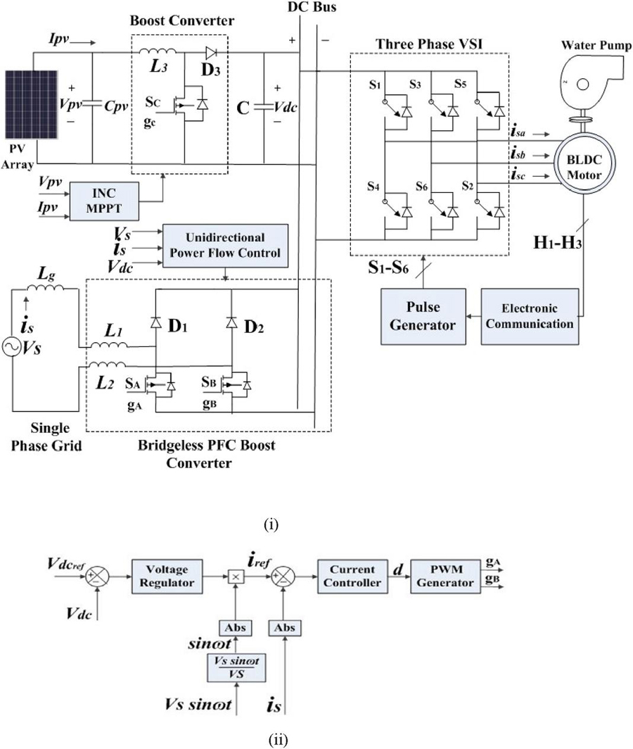
Figure 1 (i) Structure for water pumping system (ii) Unidirectional power flow.
3 Bridgeless PFC Boost Converter
The topology used for unidirectional power flow to drive the BLDC motor is shown in Figure 2. This topology has an important advantage over the PFC boost converter, i.e., the switches used in the topology have minimum conduction losses. This is because, at any instant of operation, only two devices are on the current path [12–14]. There are two single boost converters used in this topology without any rectifier. It operates in CCM. Controlling the switches S and S during all half cycles of ac input voltage regulates the current as well as the output voltage.
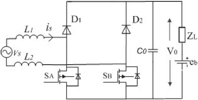
Figure 2 Bridgeless PFC boost converter topology.
When Switch S is in the on state during the positive half cycle, the current flows through S and the body diode of S. The stored energy from the inductor and capacitor is released through load during this period (0 t dTs)
| (1) | |
| (2) |
When the switch S is in an off state, the current passes via D1, the capacitor, and the body diode of the switch S. (dTs t Ts)
| (3) | |
| (4) |
During the negative half of the AC input voltage, when Switch S is in the on state, the current flows through S and the body diode of S. The stored energy from the inductor and capacitor is released through load during this period (0 t dTs)
| (5) | |
| (6) |
When the switch S is in an off state, the current passes via D1, the capacitor, and the body diode of the switch S. (dTs t Ts)
| (7) | |
| (8) |
During the time interval of 0 t dTs and dTs t Ts, the mathematical model of converter is given in (9) and (10)
| (9) | |
| (10) |
Where, , and are source voltage, current, switching period, output capacitance, the impedance of the motor, input inductance, and back emf respectively.
For small-signal analysis, the system is analyzed around the operating point with a small perturbation and is represented as
| (11) |
By substituting Equation (11) in Equations (9) and (10), the modified equation
Where, , .
Since is the operating point, . With these data, by considering only the information of the operating point, the states can be calculated as
| (13) |
The perturbed small-signal model becomes
| (14) |
Since and are known, by using Equation (14), the current and voltage loop transfer function shown in Figure 3 can be obtained.
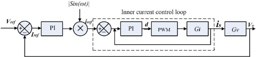
Figure 3 Block diagram of control loop of bridgeless PFC boost converter.
3.1 Current Control Loop
The transfer function is obtained by assuming .
| (15) |
This yields
| (16) |
Where, .
3.2 Voltage Control Loop
The transfer function is obtained from (14) by assuming
| (17) |
This yields
| (18) |
The transfer function in Equation (18) can be simplified as
| (19) |
Where .
The Equation (19) can be separated as
| (20) | ||
| (21) |
By combining (20) and (21), the transfer function becomes
| (22) |
4 System Design
4.1 Design and Estimation of PV Array
For a motor rated at 1.1 kW, a 1.26 kW photovoltaic array is designed. The higher rating of the photovoltaic array is chosen to compensate for converter losses. A PV module with a and of 15.14 V and 4.3 A was selected here. The MPP voltage of the PV array is chosen as V. Other parameters are estimated as
| (23) |
Where is the photovoltaic power at MPP.
Number of series-connected modules
| (24) |
Number of Parallel connected modules
| (25) |
4.2 Design of DC-DC Boost Converter
The estimation of the input inductor is part of its design. The duty cycle is evaluated as [15, 16]
| (26) |
Here, is the DC link voltage.
is evaluated as
| (27) |
Where is the switching frequency and is the in inductor current ripple.
4.3 Design of Bridgeless PFC Boost Converter
Considering CCM operation, the value of inductor L, for bridgeless PFC power boost converter, is calculated as [17]
Where is the switching frequency and is the maximum allowed current ripple through the inductor.
4.4 Design of DC-link Capacitor
Its value was evaluated as [18]
| (29) |
Where is a DC bus average current, is the line frequency rad/sec. is DC bus voltage ripple.
4.5 Design of Water Pump
The selection and design of the water pump based on its torque-speed characteristic as [19]
| (30) |
, and are pump constant, load torque in N-m and speed in rad/se.
4.6 Power Stage Design
4.6.1 Inductor loss
The inductor RMS current and the corresponding copper loss are [20]:
| (31) | ||
| (32) |
4.6.2 MOSFET loss
| (33) | ||
| (34) |
(Assuming )
The average input current is given as:
| (35) | ||
| (36) | ||
| (37) | ||
| (38) |
4.6.3 Diode loss
The diode conduction loss can be obtained as
| (39) | ||
| (40) |
The Switching loss is
| (42) |
5 Control Schematic
5.1 Electronic Communication of BLDC Motor
Voltage source inverter is used to drive the motor, which is operated by an electronic commutation system [21]. Electronic commutation uses a decoder logic circuit to commutate the currents flowing through its windings in a predetermined sequence [22]. The input currents are symmetrically placed at the centre of the back emf for 120. Three hall signals at an interval of 60 are generated by three hall sensors in consonance with the rotor position [23, 24]. Using a decoder circuit, these three signals are then converted into six switching pulses for a voltage source inverter at the fundamental frequency.
5.2 Speed Control of Motor-Pump
Since grid power support is feasible, the common bus voltage is set to its rated value for supplying the full volume of water. This allows the brushless DC motor to operate at its rated speed regardless of the environmental conditions. The phase current sensor is removed from the motor drive in this case. The bus voltage is not sustained at its rated value when utility grid power is unavailable. As a result, the speed is controlled by an inconsistent bus voltage that varies depending on the amount of solar irradiation available [25].
5.3 Unidirectional Power Flow Control
The power flow from the grid to the DC bus is regulated by the proposed control instantaneously. The control system is demonstrated in Figure 1(ii). The power flow control system has a two cascade control architecture consisting of a PI controller. The real DC bus voltage is compared with the reference value, and the difference is delivered to the PI controller for voltage regulation. As a result, regardless of operating conditions, the bus voltage is maintained. The controller output is multiplied with sint to generate a reference current iref. The real sensed source current ‘is’ is compared to the reference current, and the difference is delivered to a PI controller [26]. The duty cycle d is fed to the PWM generator, which generates pulses for the converter.
6 Simulation Results and Discussion
The proposed system is demonstrated in different states of operation using the MATLAB/Simulink platform, and comparative evolution of power quality using the different converters is presented.
6.1 Starting and Steady Performance
6.1.1 Motor-pump fed by only PV array
The various photovoltaic array, as well as motor parameter responses, can be seen in Figure 4. The PV array produces 1.26 kWp at MPP with a 1000 w/m irradiance, as shown in Figure 4(i). Hence, the motor operates at the speed and torque of its rated value, i.e. 3000 rpm, 3.5 N-m, which results in the delivery of full capacity of water. The motor parameters, i.e. bus voltage, , speed, , torque, , back emf, ea, winding current, , shown in Figure 4(ii). There is no need for grid power since the photovoltaic array provides enough power for the motor pump.
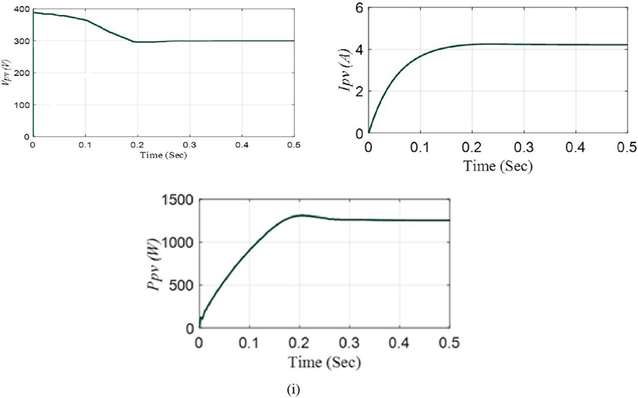
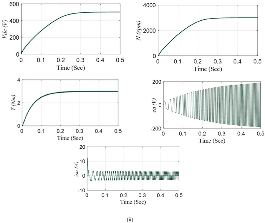
Figure 4 Steady-state performance of the system (i) Photovoltaic responses (ii) BLDC motor responses.
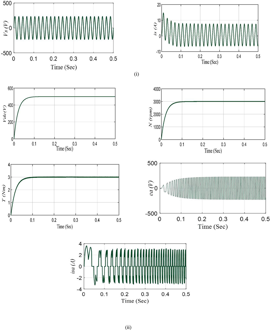
Figure 5 Steady-state performance of the system (i) Grid responses (ii) BLDC motor responses.
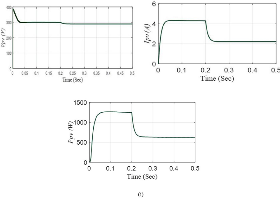
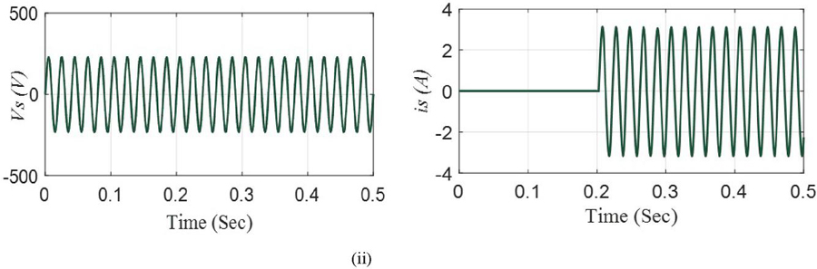
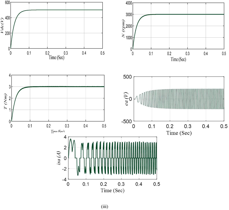
Figure 6 Dynamic state performance of the system (i) Photovoltaic responses (ii) Grid responses (iii) BLDC motor response.
6.1.2 Motor-pump fed by the only grid
The BLDC motor–pump extracts full power from the utility grid when there is a need for water pumping at night. A sinusoidal source current is extracted from the utility grid and modulates the bus voltage of 500 V represented in Figure 5(i). The motor achieved the speed and torque of rated the value shown in Figure 5(ii).
6.2 Dynamic Performance
A dynamic condition is described as a rapid change in solar irradiance caused by a change in environmental conditions. The proposed system is demonstrated by considering that a 1000 W/m of irradiance is available up to 0.2 sec as demonstrated in Figure 6(i). Hence, there is no requirement for utility grid support and the grid current is not drawn as presented in Figure 6(ii). Since solar insolation drops from an irradiance of 1000 w/m to half value i.e.500 w/m in 0.2 seconds, the photovoltaic power needed to run the motor pump at full capacity is presumed to be insufficient. The utility grid now supplies power. As a result, the motor receives power from both the grid and the photovoltaic array. After 0.2 seconds, a source current is drawn from the grid, maintaining the bus voltage of 500 V, as demonstrated in Figure 6(ii). Hence, the BLDC motor pump runs at speed of 3000 rpm, and the delivery of water is not disrupted, as can be seen in Figure 6(iii).
6.3 Power Quality Aspect Comparative Study
The grid power quality and the efficiency of the system using a converter topology i.e., bridgeless PFC boost converter is compared with a system using a conventional converter. In the Table 1 the comparison is presented. It is found that the proposed system reduced THD from 4.75% to 3.34%, improved the power factor to 0.99 and consequently improve the efficiency to 99.8% than the conventional PFC boost converter. The source current, its harmonic spectrum, and THD of both bridgeless and conventional boost converters are demonstrated in Figure 7.
Table 1
| PFC Boost Converter | Power Factor | THD (%) | Efficiency (%) |
| Conventional PFC boost converter | 0.96 | 4.75 | 96.4 |
| Bridgeless PFC boost converter | 0.99 | 3.34 | 97.8 |
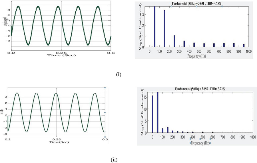
Figure 7 Source current and THD of (i) Conventional PFC boost converter (ii) Bridgeless PFC boost converter.
6.4 Robustness Plot
Figure 8 show the bode plot of the inner current control loop and outer voltage control loop, respectively.
The bode plot of the voltage control loop has a phase margin of 87.1 deg indicating the system is robust enough to mitigate the unmodelled dynamics and uncertainties. Similarly, the bode plot of the current control loop ensures that the system is robust and stable, with a cross over frequency of 7.93 kHz and a phase margin of 90.2 degrees.
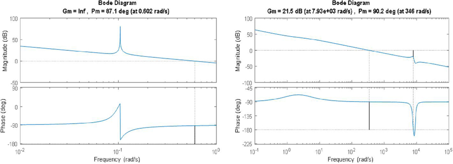
Figure 8 Bode plot of (i) outer voltage loop (ii) inner current loop.
7 Real-Time Implementation with OPAL-RT
The OPAL-RT (OP-5700) HIL simulator has been used to validate the real-time performance of the proposed work. The simulator is a state of the art real-time simulator with inbuilt support for simulink model. RT-Lab software which is bundled with the simulator has been used to implement the simulink model in the simulator. The simulator uses a Xilinx made Virtex 7 FPGA board for real-time simulation. The simulator has an Intel Xeon E5 processor with 16 cores (each core having a speed of 3.2 GHz) and 32 GB DRAM. The real-time simulator has analog I/O channel which can generate voltage in the range of 16 V. To observe the output voltage in the DSO a standard DB37 breakout board has been used, which can be connected to the I/O channels of the simulator.

Figure 9 OPAL-RT simulator OP5700 interfaced with console PC.
7.1 Starting and Steady-state Performance
7.1.1 Motor-pump fed by only PV array
The photovoltaic array provides the power needed for the water pump to operate under full irradiance conditions as presented in Figure 10(i). A PV power of 1.26 W is available under full irradiance conditions. As a result, the motor pump is set to run at 3000 rpm with a torque of 3.5 Nm. The motor parameters i. bus voltage, , speed, , torque, , back emf, ea, winding current, as presented in Figure 10(ii).
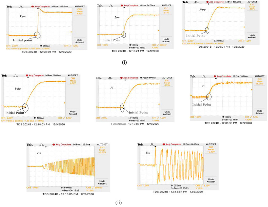
Figure 10 Real-time responses with OPAL-RT (i) Photovoltaic parameters (ii) BLDC motor parameters.
7.1.2 Motor-pump fed by only grid
During night time when there is a requirement for water pumping, grid supplies full power to the motor-pump as presented in Figure 11(i). Grid supply a sinusoidal current of 6.8 A, when controlling the bus voltage of 500 V, as conferred in Figure 11(i). The motor pump attains a speed and torque of rated value, i.e. 3000 rpm and 3.5 Nm, as depicted in Figure 11(ii).
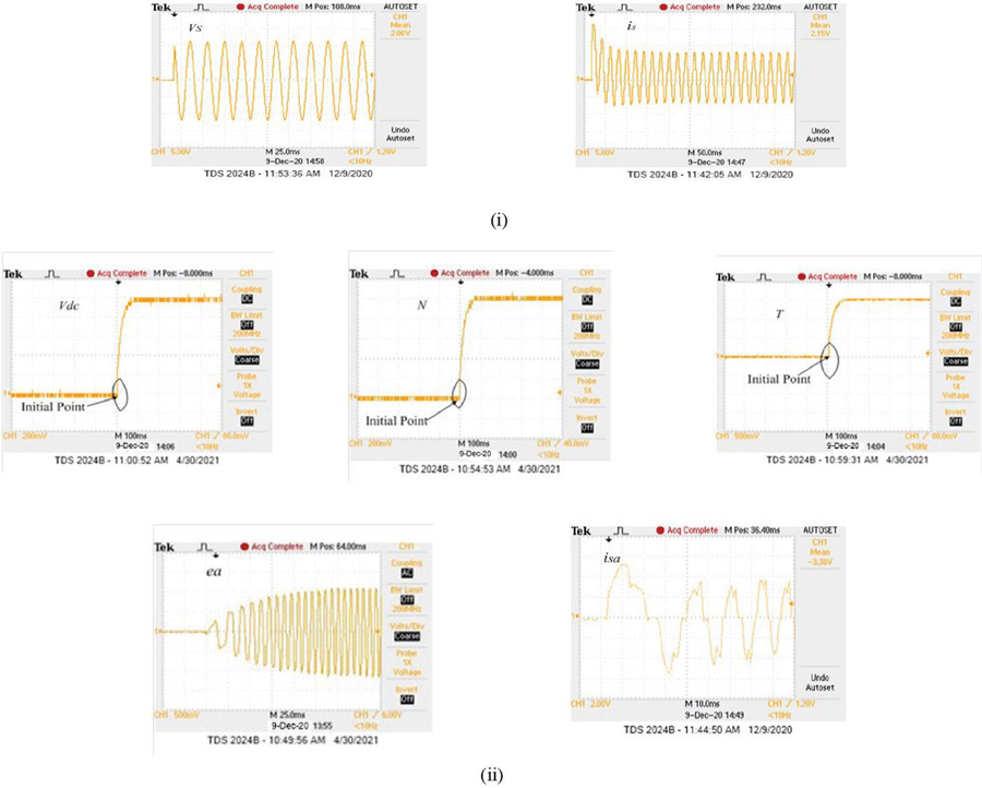
Figure 11 Real-time responses with OPAL-RT (i) Grid parameters (ii) BLDC motor parameter.
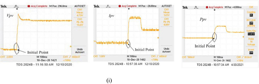
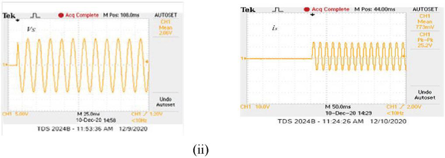
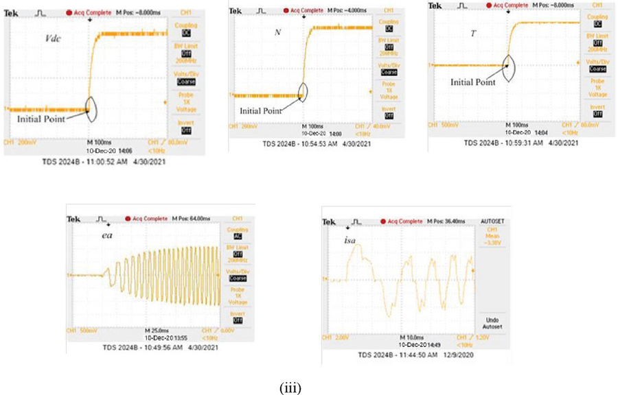
Figure 12 Real-time responses with OPAL-RT (i) Photovoltaic parameters (ii) Grid parameters (iii) BLDC motor parameters.
7.2 Dynamic State Performance
The dynamic conditions are realized by variations in weather conditions. Depending on the climate conditions the grid supplies power to the motor pump. As depicted in Figure 12(i) the solar irradiance suddenly drop from 1000 W/m to its half value i.e. 500 W/m at 0.2 sec. Before 0.2 seconds, the solar photovoltaic array supplies enough power to the pump to operate at full extent. However, because of decreases in solar insolation to 500 W/m, the unidirectional power control enables the grid to supply power as conferred in Figure 12(ii). Hence the motor pump runs at its rated value to supply the full volume of water consistently shown in Figure 12(iii).
8 Conclusion
An improvement to the power quality of the grid by using a bridgeless PFC boost converter for the proposed system is tested using MATLAB/ Simulink. An OPAL-RT simulator, OP5700, is used to validate the system in real-time. The utility grid has been supported as a power backup to the motor pump. The bridgeless PFC boost converter with power flow control shares the required power depending on the environmental conditions for pumping the water uninterruptedly at the full capacity of the motor pump. Through simulation studies, the performance of the proposed bridgeless PFC boost converter topology is compared with that of the PFC boost converter topology. The results show that a PF of 0.9, a THD of nearly 3.34% and an efficiency of 99% can be achieved by using a bridgeless PFC boost converter. It is found that this converter has provided much better performance in terms of power factor, third harmonic distortion and efficiency as compared to the PFC boost converter topology. The power quality of the system is well within the specified standard of IEC 61000-3-2 and IEEE 519-1992 under all working conditions.
Appendix
1. Parameters of the solar PV module:
Table 2
| Open circuit voltage, | 19.8 V |
| Short circuit current, | 4.8 A |
| MPP voltage, | 15.14 V |
| MPP current, | 4.3 A |
2. Parameters of the motor:
Table 3
| Power, | 1.1 kW |
| Speed, N | 3000 rpm |
| Torque, T | 3.5 Nm |
| Pole | 4 |
| Stator resistance, Rs | 2.87 |
| Stator inductance, Ls | 8.5 mH |
3. Parameters of the Grid:
Table 4
| Voltage | 230 V |
| Frequency | 50 Hz |
| Phase | Single |
4. Rating and specifications of switches
| MOSFET | IRF830,500V,4.5 A |
| Diode | MUR1560,400-600V,15A |
References
[1] C. Jain, B. Singh, An adjustable DC link voltage based control of multifunctional grid interfaced solar PV system, IEEE J. Emerg. Sel. Topics Power Electron., 2017, 5(2):651–660.
[2] J.S. Chandel, M.N. Naik, R. Chandel, Review of solar photovoltaic water pumping system technology for irrigation and community drinking water supplies, Renewable and Sustainable Energy Reviews, 2015, 49:1084–1099.
[3] S.M. Niapour, S. Danyali, M. Sharifian, M. Feyzi, Brushless DC motor drives supplied by PV power system based on Z-source inverter and FL-IC MPPT controller, Energy Conversion and Management, 2011, 52(9):3043–3059.
[4] P. Periasamy, N. K. Jain, I.P. Singh, A review on development of photovoltaic water pumping system, Renewable and Sustainable Energy Reviews, 2015, 43:918–925.
[5] R. Kumar, B. Singh, ‘Solar PV-Battery Based Hybrid Water Pumping System Using BLDC Motor Drive. IEEE First Int. Conf. Power Electron’, Intell. Control Energy Syst. (ICPEICES). 2016.
[6] A. Serhan, E. M Ahmed, ‘Effect of the different charging techniques on battery life-time: review’, Int. Conf. Innovative Trends in Computer Engineering (ITCE), Aswan, 2018:421–426.
[7] A. Boussaibo, M. Kamta., J. Kayem, D. Toader, S. Haragus, A. Maghet, ‘Characterization of photovoltaic pumping system model without battery storage by MATLAB/Simulink’, 9th International Symposium on Advanced Topics in Electrical Engineering (ATEE). 2015: 774–780.
[8] R. Kumar, B. Singh, Brushless DC motor-driven grid-interfaced solar water pumping system, IET Power Electronics, 2018, 11(12): 1875–1885.
[9] M.A. Elgendy, D.J. Atkinson, B. Zahawi, Experimental investigation of the incremental conductance maximum power point tracking algorithm at high perturbation rates, IET Renew. Power Gener, 2016, 10(2): 133–139.
[10] D.C. Huynh, M.W. Dunnigan, Development and comparison of an improved incremental conductance algorithm for tracking the MPP of a solar PV panel, IEEE Trans. Sustain. Energy, 2016, 7(4):1421–1429.
[11] N. Karami, N. Moubayed, R. Outbib, General review and classification of different MPPT techniques, Renew. Sustain. Energy Rev, 2017, 68(1):1–18.
[12] W.Y. Choi, J.M. Kwon, E.H. Kim, J.J. Lee, B.H. Kwon, Bridgeless boost rectifier with low conduction losses and reduced diode reverse recovery problems, IEEE Trans. Ind. Electron, 2007, 54(2):769–780.
[13] P. Kong, S. Wang F.C. Lee, Common mode EMI noise suppression for bridgeless PFC converters, IEEE Trans. Power Electron, 2008, 23(1):291–298.
[14] L. Huber, Y. Jang, M.M. Jovanovic, Performance evaluation of bridgeless PFC boost rectifiers, IEEE Trans. Power Electron, 2008, 23(3):1381–1389.
[15] M. H. Rashid, Power Electronics Handbook: Devices, Circuits, and Applications,” 3rd ed. Oxford, UK: Elsevier Inc; 2011.
[16] N. Mohan, M. Tore Undeland, P. William Robbins, Power Electronics: Converters, Applications and Design, 3rd ed. New Delhi, India: Jhon Wiley & Sons Inc; 2010.
[17] T. K. Jappe, M. K. Lohn, S. A Mussa, GaN-based single-phase bridgeless PFC boost rectifier. The Journal of Engineering, 2017, 19(17): 3614–317.
[18] S. Shukla, B. Singh, Improved power quality converter for three-phase grid-interfaced PV array fed reduced current sensor-based induction motor drive for water pumping, International transaction on Electrical Energy System, 2019, 30(4):2–20.
[19] FAO Aashoor, FVP Robinson, Maximum power point tracking of photovoltaic water pumping system using fuzzy logic controller, 48th Int. Universities Power Engineering Conf. 2013; 1–5.
[20] S. Abdel-rahman, F. Sückler, and K. Siu, “PFC boost converter design guide,” 2016.
[21] K. S. Rathore, U. K. Kalla, D. K. Palwalia, B. Singh, An improved power quality modified DC-DC converter fed PMBLDC motor drive system for household applications, International transaction on Electrical Energy System. 2020.
[22] B. Singh, V. Bist, A BL-CSC converter-fed BLDC motor drive with power factor correction, IEEE Trans. Ind. Electron, 2015, 62(1): 172–183.
[23] V. Bist, B. Singh, A unity power factor bridgeless isolated Cuk converter-fed brushless DC motor drive. IEEE Trans. Ind. Electron, 2015, 62(7):4118–4129.
[24] R. Kumar, B. Singh, BLDC motor driven solar PV array fed water pumping system employing zeta converter, IEEE Trans. Ind. Appl. 2016, 52(3):2315–2322.
[25] R. Kumar, B. Singh, Grid Interactive Solar PV-Based Water Pumping Using BLDC Motor Drive, IEEE Transactions on Industry Applications, 2011, 55(5):5153–5165.
[26] U. Yilmaz, O. Turksoy, A. Teke, Improving a battery charger architecture for electric vehicles with photovoltaic system, International transaction on Electrical Energy System, 2020, 44(6):4376–4394.
Biographies

Biranchi Narayan Kar received his BE in Electrical Engineering from Seemanta Engineering College, Jharpokharia, Odisha, India in 2005 and an M.Tech in Power Electronics and Drives from National Institute of Technology Rourkela, Odisha, India in 2011. He is currently working toward his PhD in the Electrical Engineering at Motilal Nehru National Institute of Technology, Allahabad, Pryagraj, Uttar Pradesh, India. His research interests include power electronics Drives and Renewable Energy.

Paulson Samuel received the Bachelor of Engineering (Electrical) degree from the G. S. Institute of Technology and Science, Indore, India, in 1984, and the Master of Engineering in Computer Science and Engineering degree from Motilal Nehru National Institute of Technology, Allahabad, India, in 1998. He completed his PhD in electrical engineering at Motilal Nehru National Institute of Technology, Allahabad, India, in 2013. From 1990 onward, he has been a faculty member in the Department of Electrical Engineering, Motilal Nehru National Institute of Technology, where he is presently a Professor. From 1984 to 1990, he was an Engineer at the National Thermal Power Corporation, New Delhi, India. His research interests include power quality, distributed generation, automation, control of power converters, and multilevel inverters.

Amit Mallick received his B.Tech in Electrical Engineering from NM Institute of Engineering and Technology, Bhubaneswar Odisha, India in 2013 and his MTech in Power System from VSSUT, Burla, Odisha, India in 2011. He is currently working as Assistant Professor in the Electrical Engineering Dept at VSSUT, Burla, Odisha. His research interests include Power electronics, Power systems and Microgrid operation and protection.

Jatin Kumar Pradhan received his BE in Electrical Engineering VSSUT, Burla, Odisha in 2008, MTech in Power Electronics and Drives from National Institute of Technology Rourkela, Odisha, India in 2011 and PhD from IIT Bhubaneswar, Odisha, India in 2019. He is currently working as Assistant Professor in the Electrical Engineering Dept at VSSUT, Burla, Odisha, India. His research interests include Control of MIMO System, Robust Control, Control System Applications.
Distributed Generation & Alternative Energy Journal, Vol. 38_5, 1477–1504.
doi: 10.13052/dgaej2156-3306.3856
© 2023 River Publishers