A New FL-MPPT High Voltage DC-DC Converter for PV Solar Application
Tole Sutikno1, 2,*, Arsyad Cahya Subrata1, 2 and Awang Jusoh3
1Department of Electrical Engineering, Universitas Ahmad Dahlan, Yogyakarta, Indonesia
2Embedded Systems & Power Electronics Research Group, Yogyakarta, Indonesia
3Department of Electrical Power Engineering, Universiti Teknologi Malaysia, Johor, Malaysia
E-mail: tole@ee.uad.ac.id; arsyad.subrata@te.uad.ac.id; awang@fke.utm.my
*Corresponding Author
Received 16 July 2021; Accepted 28 February 2022; Publication 24 June 2022
Abstract
To reduce the effects of global warming, there is an increasing need for renewable energy sources. Several studies have been carried out on photovoltaic (PV) systems to maximize their potential as an alternative electricity generator. However, various power converters for high voltage ratio applications have multiple drawbacks. This research was carried out to develop a power converter topology connected between the PV and the load for the need. In this research, the high step-up DC-DC converter for high-voltage gain conversion ratio and high efficiency is proposed. Furthermore, the fuzzy logic-based Maximum Power Point Tracking (MPPT) technique connected to the power converter was used to maximize the power converted from PV in changing atmospheric conditions. The MPPT control with fuzzy logic controller (FLC) was analysed and compared with the perturb and observe (P&O) algorithm. The results showed that the FLC algorithm could control the high step-up (HSU) DC-DC converter with an output voltage of 29% higher than the P&O algorithm.
Keywords: Fuzzy logic, maximum power point tracking, DC-DC converter, photovoltaic, power converter, perturb and observe algorithm, renewable energy.
1 Introduction
Photovoltaic (PV) system is one of the fastest-growing technologies in line with the severe energy crisis and environmental issues such as pollution and the effects of global warming. Meanwhile, the energy conversion efficiency generated from PV is relatively small [1–5]. Therefore, a lot of research has been carried out to develop PV systems regarding basic materials that form PV and the power converter side. This research was carried out to maximize the energy conversion results of a PV system and was divided into two main topics [6]. The first topic was related to new, high-efficiency, and low-cost PV cells and modules. In contrast, the second topic was related to the power converter topology and control strategy used.
Various topologies have been developed from the power converter point of view to maximize the energy conversion results obtained from PV. In general, conventional DC-DC converters were used for low-power applications [7]. Meanwhile, for applications requiring high voltage ratios, the development of a power converter topology has also received special attention [8–10]. Theoretically, a significant voltage gain in the DC-DC converter is achievable by providing a high duty ratio. Meanwhile, the increase in voltage generated by a high duty ratio is limited due to its electronic components, such as the effect of switches, diodes, equivalent series resistance (ESR) of inductors and capacitors. Therefore, many researchers have developed converters with high step performance, low cost, and high efficiency in power applications requiring high voltage ratios and various topologies.
Furthermore, Afzal et al. [11] and Ebrahimi et al. [12] developed a boost converter with a coupled inductor for high step-up applications due to the simplicity of the structure. However, this topology results in low efficiency at low power levels due to the leakage in coupled inductors, leading to increased conduction loss in semiconductors and copper losses in inductors. This problem is usually resolved with resistor-capacitor-snubber diodes, but it causes additional power loss [13]. The current-fed converter topology uses a transformer based on switched capacitors suitable for low power application systems. This converter produces zero magnetic DC offset and a low input ripple due to its current-fed structure [14]. Also, Sha et al. [15] optimized the current-fed dual active bridge DC-DC converter.
Meanwhile, this converter’s problem is poor voltage regulation on the output side, high voltage, and current surges through semiconductor devices caused by the charging and discharging of switched capacitors [16]. The cascaded converter also produces high voltage ratios but working unstably is its major drawback. Li et al. [17] also proposed a stable converter with an approach based on describing its function methods but, its efficiency is low because it requires two processes. Quadratic Boost Converter (QBC) topology connects two converters in series using one switch. Without optimization, the efficiency of QBC is lower than conventional boost converters. Furthermore, Wang et al. [18] proposed a different mode of operation, which yielded an efficiency of 90%.
Meanwhile, Lee [19] used a QBC with the coupled inductor. The passive voltage clamp connected to the power switch makes recycled energy stored in the leakage inductor of the coupled inductor; therefore, the power switch spike was reduced. Also, the resulting voltage ratio was the same as the one in the cascaded converter. The output voltage with high ratio and efficiency produced by the high step-up (HSU) converter was proposed by Dahono [20] and has been used for maximum power point tracking (MPPT) technique for PV systems, but still employed a conventional controller.
To produce high ratio output voltages, DC-DC converter topologies for PV systems should have high-voltage gain and deliver increased efficiency. In this research, the high step-up DC-DC converter for high-voltage gain conversion ratio and high efficiency is proposed. Modeling and simulation of MPPT technique using the high-voltage gain DC-DC converter based on a simple fuzzy logic controller (FLC) are presented in this paper. The FLC-based converter is compared with the perturb and observe (P&O) algorithm. Section 2 discusses the modeling and characteristic of PV modules using MATLAB/Simulink and describes the basic MPPT. Meanwhile, Section 3 describes a modeling of the HSU converter used and the MPPT technique based on FLC. Furthermore, the results and discussion are presented in Section 4, followed by conclusions in Section 5.
2 Materials and Methods
2.1 Modeling PV Module
Since the discovery of PV silicone crystalline designed for outdoor use in 1950 by Bell Labs [21], till now, there are two PV cell models still in use single-diode [22–24] and double diode [25, 26]. The single-diode model, shown in Figure 1, is superior and widely used due to its accuracy and complexity [27]. The output current of a single-diode model of the PV cell is expressed as
| (1) |
where the module is represented in M, , and are the voltage, current, and series resistance module, and is the number of cells connected parallel and in series, and are photocurrent and saturation current of the module, is the open-circuit voltage module, q is the electron charge , is Boltzmann constant T is the cell working temperature. At the same time, A is the diode constant ideality of cells depending on PV technology. With Equation (1), the characteristics of the PV module can be formed and developed to obtain the electrical character of the PV module shown in Figure 2.
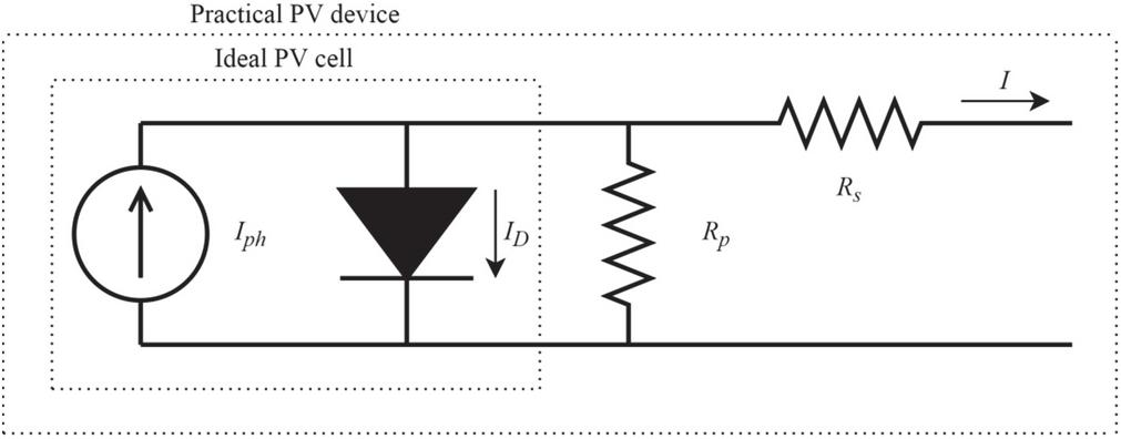
Figure 1 Single-diode model PV cell equivalent circuit.
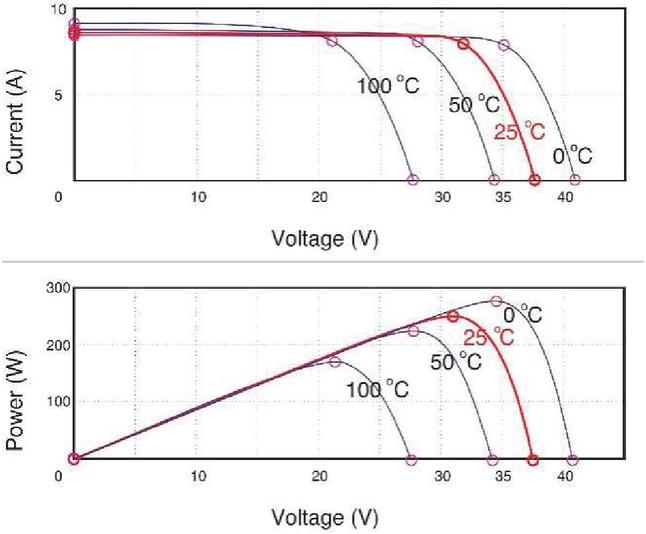
Figure 2 and characteristic.
The photocurrent module depends on solar irradiation, and it is also influenced by temperature, as shown in the equation.
| (2) |
where is the short-circuit current of the cell at the temperature of 25C at , is the temperature coefficiency of short-circuit cell current, is the cell reference temperature, meanwhile, is the solar irradiance level in .
The saturation current of the module varies with the cell temperature given by
| (3) |
where reverse saturation current at the reference temperature and solar radiation is the band-gap energy of the semiconductor used in the cell.
The reverse saturation module at the reference temperature is planned as,
| (4) |
where the open-circuit voltage at the reference temperature.
2.2 Maximum Power Point Tracking
To use energy optimally, PV is installed in an environment where the sun’s rays are not obstructed. Meanwhile, irradiation and temperature due to the atmosphere affect the efficiency of the power output [28]. Therefore, many researchers have developed the MPPT technique to obtain the maximum energy conversion efficiency to solve the efficiency problem in PV systems. MPPT is a method for tracing the Maximum Power Point (MPP), using the parameters such as voltage, current, and/or power as input. At the same time, the output from MPPT is a PWM signal or a change in a duty cycle that controls the power converter used.
MPPT is a technique used to trace the MPP of PV by moving its operating module point to its MPP. The and curves of the PV module show that the maximum power is only available under one specific functional condition called MPP. Also, its location varies with changes in irradiation and operating temperature. A simple example can be seen in the curve shown in Figure 3, produced from a PV module with a maximum voltage of 18.6 V (measured at a cell temperature of 25C, connected to a DC load of 12 V). The output voltage of the PV module varies with the cell temperature.

Figure 3 Curve of the characteristics of the PV module connected to a 12 V load.
The operating point of the PV module is not at its peak when it is directly connected to the load. For example, in Figure 3, the PV output power is 75 W, so the power generated is less than the maximum power available in the PV module. The electrical operation point can be moved to the high-power point by varying the impedance in the PV module. Furthermore, to change the impedance of the PV circuit to the load circuit, a DC-DC converter is used by changing its duty ratio [29].
The algorithm used to discover MPP is the hill-climbing method, namely Perturb and Observe (P&O). The conventional algorithm is easy to build algorithms because it does not require PV characteristics or solar intensity and cell temperature measurements. Meanwhile, the P&O algorithm is more straightforward and flexible, making it useful for commercial applications [30]. Furthermore, P&O works by perturbing the PV operating point to increase or decrease the control parameters in a small step size and measure the output power of the PV array before and after perturbation. If the power increases, the algorithm will perturb the system in the same direction. Also, it will perturb the system in the opposite direction if the power decreases [31]. P&O techniques use reference voltage and reference current perturbation or direct duty ratio perturbation which are widely used today.
Meanwhile, the P&O algorithm fluctuates in the MPP estimate around the actual reference MPP voltage depending on the perturbation size [32]. The resulting fluctuation becomes high if the step size used is significant. Also, if the step size is too small, the tracking speed to reach MPP will take a long time.
Furthermore, power oscillations also occur in both stable and unstable atmospheric conditions [33]. Due to the potential and advantages of Artificial Intelligent (AI), various AI-based algorithms are widely used in the MPPT technique. Furthermore, FLC, an intelligent control algorithm, is widely used in recent years because of its good performance and structural simplicity [6, 34]. The results reported by these researchers show that the FLC algorithm used for duty cycle control in the MPPT technique performs better than conventional techniques.
2.3 High Step-up DC-DC Converter
The system developed in this research is a stand-alone PV system, as shown in the general block diagram in Figure 4. The system consists of a PV generator, HSU DC-DC converter with MPPT based on fuzzy logic to adjust the converter’s duty ratio and resistive loads.
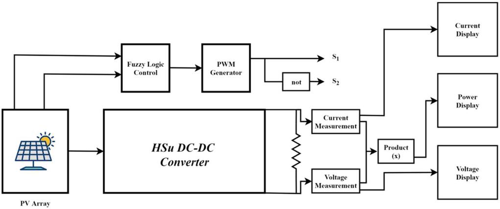
Figure 4 General block diagram of the system.
The converter used in this research was DC-DC buck-boost converter, producing a high voltage gain. This converter modification combines a derived boost and buck DC-DC converter, Dahono [20]. The conventional DC-DC boosts converter is shown in Figure 5(a).
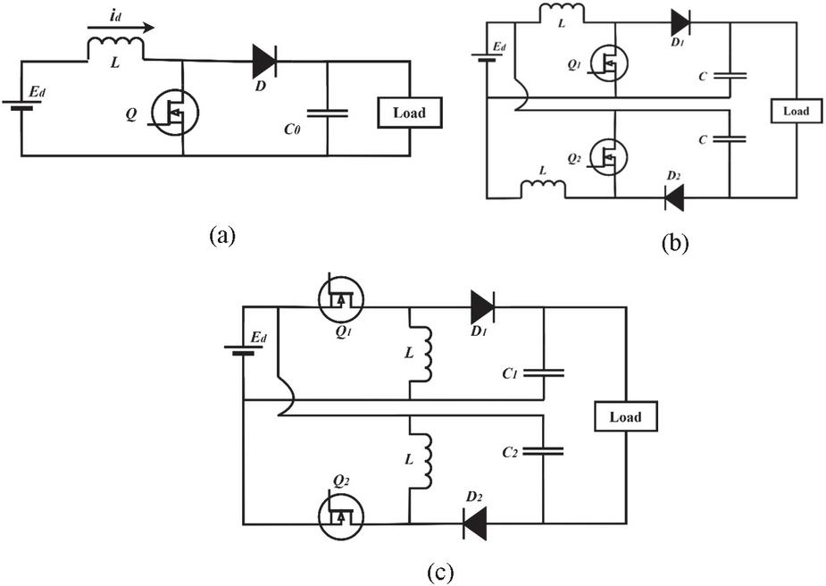
Figure 5 DC-DC converter (a) boost, (b) boost derived converter, and (c) buck-boost derived converter.
The voltage gain of the conventional DC-DC boost converter is
| (5) |
where is the duty factor of the transistor . While the output voltage is given by
| (6) |
Furthermore, the conventional DC-DC boost converter is differentiated with a parallel-connected input and a series-connected output, as shown in Figure 5(b). This connection increases the load ratio of the converter. Therefore, the voltage gain is given by
| (7) |
while the output voltage at steady-state condition is
| (8) |
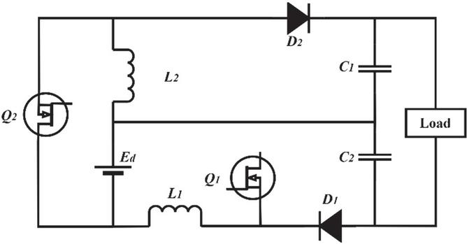
Figure 6 HSU converter.
Furthermore, the buck-boost converter is differentiated by the same method. This converter is shown in Figure 5(c), and it also produces the same voltage ratio (5). However, it has discontinuous input currents with significant ripple content, which reduced PV module performance or load. The total ripple input and output can be reduced by controlling two converters as two-phase converters.
The HSU converter was produced by combining a diversified boost and buck-boost converter. The converter made is shown in Figure 6, with the resulting voltage ratio equal to the one given by (10). In addition, the switch in this converter is used to reduce the ripple content of the switching device in a two-phase converter, as shown in Figures 5(b) and 5(c).
The RMS value of the output voltage ripple of this converter is
| (9) |
Meanwhile, the output voltage ripple for duty cycles more than half is
| (10) |
3 Fuzzy Logic Control for MPPT
The control method using the FLC algorithm has been developed for many applications. FLC implementation is rapidly increasing because of its simplicity and does not require mathematical modeling data [34–36]. Furthermore, FLC shows good performance in overcoming non-linear systems [29, 33, 37, 38].
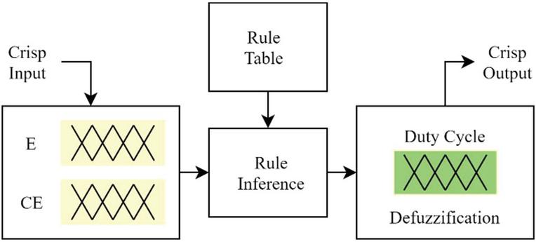
Figure 7 The basic structure of the FLC.
The FLC algorithm design has three main stages: fuzzification, rule evaluation, and defuzzification, as shown in Figure 7. At the fuzzification stage, there is a membership function that acts as FLC inputs. The number of input membership functions affects the accuracy of the FLC algorithm. Also, in rule evaluation, FLC linguistic rules are used to provide control measures that link logical functions between input and output membership functions. Furthermore, rule evaluation generates fuzzy membership function output for each action of the input membership function. The last stage is defuzzification which predicts the value of MF output obtained as the output of the whole system.
Solar PV has non-linear properties; therefore, the FL implemented in the MPPT technique overcomes this problem. In a solar PV system, the FL input is as Error (E) and Change in Error (E), with the output as a PWM feed, which controls the converter duty cycle. The error signal is obtained from the change in the PV output power divided by the change in output voltage. The two inputs are defined as
| (11) | |
| (12) |
where is the sample time, is power, the PV voltage, and is the previous PV power and voltage, respectively. shows that the operating load-point is located on the left or right, while the direction of motion of the point.
The FLC evaluates the output power of the PV and determines the change in power relative to voltage . If the value is greater than zero, the controller changes the PWM cycle to increase the voltage until it reaches the maximum power (). Conversely, if the value is less than zero, the controller changes the PWM cycle to reduce the voltage until it reaches the MPP.
3.1 Fuzzification
As shown in Figure 8, fuzzification is the initial process with input as crisp numbers. Furthermore, there are two input membership functions in estimating E and E in the proposed FLC algorithm. Each input and output have five triangular subsets, namely NB (negative big), NS (negative small), Z (zero), PS (positive small), and PB (positive big). Also, both input and output use a symmetrical membership function.
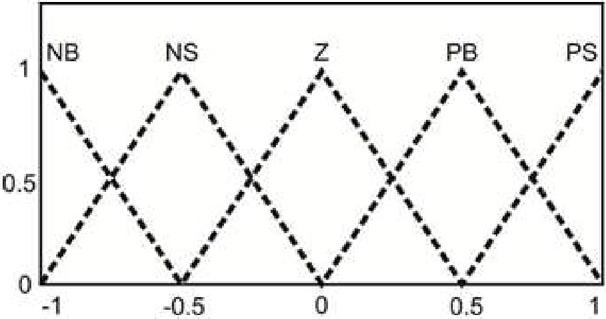
Figure 8 Membership function input and output.
This stage discovers out the value as a fuzzy number based on the membership function. In the input triangle function, the equation for discovering the fuzzy number for the left triangle which is tangent to the right triangle is given by
| (13) | ||
| (14) |
where is the left end of each triangle, is the vertex of the triangle, is the right end of the triangle, and is the input value.
3.2 Rule Evaluation (FIS and Rule Base)
Since each input has five membership functions, there are 25 rules for fuzzy control. The fuzzy numbers are therefore compared in the FIS, based on the created rule base. The rule base is a knowledge base that defines the desired relationship rules between input and output variables. The knowledge base is shown in Table 1. In contrast, the results of the rule base are illustrated with a surface in Figure 9.
Table 1 Knowledge base
| E/ | NB | NS | Z | PS | PB |
| NB | NB | NB | Z | PB | PB |
| NS | NS | NS | Z | PS | PS |
| Z | Z | Z | Z | Z | Z |
| PS | PS | PS | Z | NS | NS |
| PB | PB | PB | Z | NB | NB |
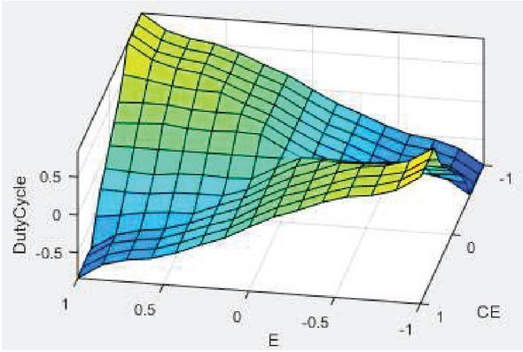
Figure 9 Rule surface of FLC.
This test uses Fuzzy Mamdani, which is based on the Min-Max function. In the first stage, when comparing fuzzy numbers, the value taken is Minimum. In the second stage, the linguistic variable will be handled with the Maximum fuzzy number if there are the same linguistic variables.
3.3 Defuzzification
In the third stage, fuzzy numbers are converted into crisp numbers as the output of the FLC. This process is based on the center of gravity. The FLC output is used to control the converter duty cycle. The equation in the defuzzification process is given by
| (15) |
where is the duty cycle, and is the output triangle value.
Error and error changes as FLC inputs are obtained from the PV output as voltage () and current (). Figure 10 shows an FLC with and . Inputs are connected to the PWM generator at its output.
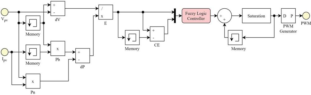
Figure 10 FLC algorithm with input and output in simulation.
4 Results and Discussion
The MATLAB/Simulink PV module model is used to test the MPPT on two converter topologies and two different algorithms. The converter models used are conventional and HSU DC-DC converters. The P&O and FLC algorithms are used in each converter model to control the duty ratio cycle. Furthermore, each converter is connected between the PV module and a resistive load. The first test was carried out by varying the PWM generator frequency, namely 5, 10, 20, and 40 kHz, and it was also carried out to discover the suitable PWM value for the HSU DC-DC converter used.
Figure 11(a) compares the PV generator output voltage simulation results on each converter with the P&O and FLV algorithms at various PWM generator values. It also shows that the oscillations in the HSU converter with P&O have large fluctuations at the PWM generator 5, 10, and 20 kHz. Meanwhile, the fluctuations in other conditions are more minor. Conversely, the output voltage ratio of the HSU-P&O converter has a higher value than the conventional P&O and FLC converters, as well as the HSU-FLC on the PWM generator of 5, 10, and 20 kHz.
At the 40 kHz PWM generator, the oscillation of conventional and HSU converters with P&O and FLC algorithms has the smallest values. Therefore, the fluctuation of the HSU-P&O converter decreased, but the resulting voltage ratio is not greater than that of the HSU-FLC converter. Furthermore, the detailed data of the HSU converter’s output voltage and oscillation values with the P&O and FLC algorithms are shown in Figure 11(b). The HSU DC-DC converter with the P&O algorithm has a voltage drop on a large PWM generator, but its oscillation decreases. Meanwhile, the HSU DC-DC converter with the FLC algorithm increases the voltage on a large PWM generator, and its fluctuation also decreases.
A further test was carried out to vary the irradiation parameters and temperature, which represent atmospheric changes. The irradiation parameters were run at 700, 800, to 1000 W/m at 25 C. Figure 12 shows the voltage, current, and output power results when testing with varied irradiation and temperature parameters.
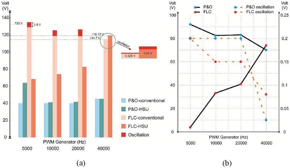
Figure 11 Comparison of voltage and oscillations (a) for each converter model with P&O and FLC, (b) details on HSU-P&O and HSU-FLC.
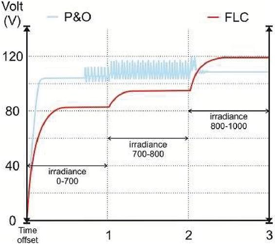
Figure 12 dari HSU-P&O dan HSU-FLC at varous irradiance.
As seen in Figure 12, the HSU-FLC output voltage at 700 to about 800 W/m irradiation has a lower ratio than HSU-P&O. Meanwhile, the oscillation at HSU-P&O is more prominent in this condition. At 1000 W/m irradiation conditions, the HSU-FLC ratio was higher than HSU-P&O. Meanwhile, the HSU-P&O oscillation decreases in this condition. In addition, HSU-FLC produced lower oscillations than HSU-P&O under all conditions.
5 Conclusions
In this research, the high step-up DC-DC converter for high-voltage gain conversion ratio and high efficiency was proposed. A simple fuzzy logic controller (FLC)-based MPP tracking (MPPT) technique using the DC-DC converter was employed to maximize the power converted from solar photovoltaic. The FLC performance was compared with Perturb and Observe (P&O) algorithm with a similar converter under varying irradiation conditions. Furthermore, the FLC was built as a duty cycle control for the DC-DC converter to track the maximum power available in the PV module. The first test was carried out to obtain a suitable PWM frequency. The results showed that the PWM generator with a frequency input of 40 kHz and the FLC algorithm for the control of the DC-DC converter produces a higher output ratio with lower oscillations than the P&O on the output voltage side. The next test was carried out by changing the irradiation value to determine the performance of the FLC and P&O techniques with the atmospheric changes. The test results of the two methods showed that they have advantages and disadvantages. The P&O algorithm produced a higher voltage ratio than FLC at low irradiation but large oscillations under the same conditions. Meanwhile, the FLC algorithm produced high voltage ratios at maximum irradiation. The resulting oscillations in the FLC algorithm were lower compared to the P&O under all conditions. This shows that the performance of the FLC algorithm applied to the DC-DC converter is better than that of P&O. Therefore, the efficiency of power transferred from PV can be maximum. Because power operation can always be controlled at a point close to MPP.
Acknowledgements
This research was funded by the Directorate General of Higher Education, Research and Technology, Ministry of Education, Culture, Research and Technology, Republic of Indonesia, for supporting this research under World Class Research (WCR) grant, contract No: 002/SKP.TT.PD/LPPM/IV/2021.
References
[1] D. Yousri, T. S. Babu, D. Allam, V. K. Ramachandaramurthy, and M. B. Etiba, “A Novel Chaotic Flower Pollination Algorithm for Global Maximum Power Point Tracking for Photovoltaic System Under Partial Shading Conditions,” IEEE Access, vol. 7, pp. 121432–121445, 2019.
[2] A. Jusoh, R. Alik, T. K. Guan, and T. Sutikno, “MPPT for PV system based on variable step size p&o algorithm,” Telkomnika, vol. 15, no. 1, p. 79, 2017.
[3] N. Kacimi, S. Grouni, A. Idir, and M. S. Boucherit, “New improved hybrid MPPT based on neural network-model predictive control-Kalman filter for photovoltaic system,” Indones. J. Electr. Eng. Comput. Sci., vol. 20, no. 3, 2020.
[4] K. L. Shenoy, C. G. Nayak, and R. P. Mandi, “Effect of partial shading in grid connected solar pv system with fl controller,” Int. J. Power Electron. Drive Syst., vol. 12, no. 1, pp. 431–440, 2021.
[5] L. Farah, A. Haddouche, and A. Haddouche, “Comparison between proposed fuzzy logic and ANFIS for MPPT control for photovoltaic system,” Int. J. Power Electron. Drive Syst., vol. 11, no. 2, p. 1065, 2020.
[6] S. Ozdemir, N. Altin, and I. Sefa, “Fuzzy logic based MPPT controller for high conversion ratio quadratic boost converter,” Int. J. Hydrogen Energy, vol. 42, no. 28, pp. 17748–17759, 2017.
[7] R. Palanisamy, K. Vijayakumar, V. Venkatachalam, R. M. Narayanan, D. Saravanakumar, and K. Saravanan, “Simulation of various DC-DC converters for photovoltaic system,” Int. J. Electr. Comput. Eng., vol. 9, no. 2, p. 917, 2019.
[8] B. Chandrasekar et al., “Non-Isolated High-Gain Triple Port DC–DC Buck-Boost Converter With Positive Output Voltage for Photovoltaic Applications,” IEEE Access, vol. 8, pp. 113649–113666, 2020.
[9] A. Pradhan and B. Panda, “A simplified design and modeling of boost converter for photovoltaic sytem,” Int. J. Electr. Comput. Eng., vol. 8, no. 1, p. 141, 2018.
[10] A. C. Subrata, T. Sutikno, S. Padmanaban, and H. S. Purnama, “Maximum power point tracking in pv arrays with high gain Dc-Dc boost converter,” in International Conference on Electrical Engineering, Computer Science and Informatics (EECSI), 2019.
[11] R. Afzal, Y. Tang, H. Tong, and Y. Guo, “A High Step-up Integrated Coupled Inductor-Capacitor DC-DC Converter,” IEEE Access, vol. 9, pp. 11080–11090, 2021.
[12] R. Ebrahimi, H. M. Kojabadi, L. Chang, and F. Blaabjerg, “Coupled-inductor-based high step-up DC–DC converter,” IET Power Electron., vol. 12, no. 12, pp. 3093–3104, 2019.
[13] S. Lee and H. Do, “High Step-Up Coupled-Inductor Cascade Boost DC–DC Converter With Lossless Passive Snubber,” IEEE Trans. Ind. Electron., vol. 65, no. 10, pp. 7753–7761, 2018.
[14] S. S. Dobakhshari, J. Milimonfared, M. Taheri, and H. Moradisizkoohi, “A Quasi-Resonant Current-Fed Converter With Minimum Switching Losses,” IEEE Trans. Power Electron., vol. 32, no. 1, pp. 353–362, 2017.
[15] D. Sha, T. Sun, and J. Zhang, “Varying Switching Frequency Control for Current-Fed Dual-Active Bridge DC–DC Converter With Constant Flux Density Change for Transformers,” IEEE Trans. Power Electron., vol. 35, no. 4, pp. 3766–3777, 2020.
[16] A. Ajami, H. Ardi, and A. Farakhor, “A Novel High Step-up DC/DC Converter Based on Integrating Coupled Inductor and Switched-Capacitor Techniques for Renewable Energy Applications,” IEEE Trans. Power Electron., vol. 30, no. 8, pp. 4255–4263, 2015.
[17] H. Li, C. Liu, X. Zhang, Z. Guo, and T. Q. Zheng, “Stability Analysis for Two-Stage Cascaded DC-DC Converters System Based on Describing Function Method,” in 2018 IEEE Energy Conversion Congress and Exposition (ECCE), 2018, pp. 4141–4147.
[18] Y. Wang, Y. Qiu, Q. Bian, Y. Guan, and D. Xu, “A Single Switch Quadratic Boost High Step Up DC–DC Converter,” IEEE Trans. Ind. Electron., vol. 66, no. 6, pp. 4387–4397, 2019.
[19] S. Lee and H. Do, “Quadratic Boost DC–DC Converter With High Voltage Gain and Reduced Voltage Stresses,” IEEE Trans. Power Electron., vol. 34, no. 3, pp. 2397–2404, 2019.
[20] P. A. Dahono, “New step-up DC-DC converters for PV power generation systems,” in 2017 International Seminar on Intelligent Technology and Its Applications (ISITIA), 2017, pp. 187–192.
[21] M. A. Green, “Silicon photovoltaic modules: a brief history of the first 50 years,” Prog. Photovoltaics Res. Appl., vol. 13, no. 5, pp. 447–455, 2005.
[22] A. K. Panchal, “I–V Data Operated High-Quality Photovoltaic Solution Through Per-Unit Single-Diode Model,” IEEE J. Photovoltaics, vol. 10, no. 4, pp. 1175–1184, 2020.
[23] I. A. Ibrahim, M. J. Hossain, B. C. Duck, and C. J. Fell, “An Adaptive Wind-Driven Optimization Algorithm for Extracting the Parameters of a Single-Diode PV Cell Model,” IEEE Trans. Sustain. Energy, vol. 11, no. 2, pp. 1054–1066, 2020.
[24] H. K. Mehta, H. Warke, K. Kukadiya, and A. K. Panchal, “Accurate Expressions for Single-Diode-Model Solar Cell Parameterization,” IEEE J. Photovoltaics, vol. 9, no. 3, pp. 803–810, 2019.
[25] F. Bradaschia, M. C. Cavalcanti, A. J. do Nascimento, E. A. da Silva, and G. M. de S. Azevedo, “Parameter Identification for PV Modules Based on an Environment-Dependent Double-Diode Model,” IEEE J. Photovoltaics, vol. 9, no. 5, pp. 1388–1397, 2019.
[26] S. Kumar, H. S. Sahu, and S. K. Nayak, “Estimation of MPP of a Double Diode Model PV Module From Explicit I–V Characteristic,” IEEE Trans. Ind. Electron., vol. 66, no. 9, pp. 7032–7042, 2019.
[27] Z. Mao, Z. Sunan, M. Peng, S. Yanlong, and Z. Weiping, “Modelling of PV module and its application for partial shading analysis – part I: model and parameter estimation of PV module,” J. Eng., vol. 2017, no. 13, pp. 1295–1298, 2017.
[28] T. Kamal, M. Karabacak, S. Z. Hassan, H. Li, and L. M. Fernández-Ramírez, “A Robust Online Adaptive B-Spline MPPT Control of Three-Phase Grid-Coupled Photovoltaic Systems Under Real Partial Shading Condition,” IEEE Trans. Energy Convers., vol. 34, no. 1, pp. 202–210, 2019.
[29] A. S. Samosir and H. Gusmedi, “Modeling and simulation of fuzzy logic based maximum power point tracking (MPPT) for PV application,” Int. J. Electr. Comput. Eng., 2017.
[30] R. Ahmad, A. F. Murtaza, and H. A. Sher, “Power tracking techniques for efficient operation of photovoltaic array in solar applications–A review,” Renew. Sustain. Energy Rev., vol. 101, pp. 82–102, 2019.
[31] M. A. Elgendy, B. Zahawi, and D. J. Atkinson, “Operating Characteristics of the P&O Algorithm at High Perturbation Frequencies for Standalone PV Systems,” IEEE Trans. Energy Convers., vol. 30, no. 1, pp. 189–198, 2015.
[32] B. Subudhi and R. Pradhan, “Adaptive predictive error filter-based maximum power point tracking algorithm for a photovoltaic system,” J. Eng., vol. 2016, no. 4, pp. 54–61, 2016.
[33] A. Hussain, H. A. Sher, A. F. Murtaza, and K. Al-Haddad, “Improved Restricted Control Set Model Predictive Control (iRCS-MPC) Based Maximum Power Point Tracking of Photovoltaic Module,” IEEE Access, vol. 7, pp. 149422–149432, 2019.
[34] H. Rezk, M. Aly, M. Al-Dhaifallah, and M. Shoyama, “Design and Hardware Implementation of New Adaptive Fuzzy Logic-Based MPPT Control Method for Photovoltaic Applications,” IEEE Access, vol. 7, pp. 106427–106438, 2019.
[35] D. N. Luta and A. K. Raji, “Comparing fuzzy rule-based MPPT techniques for fuel cell stack applications,” Energy Procedia, vol. 156, pp. 177–182, 2019.
[36] S. Assahout, H. Elaissaoui, A. El Ougli, B. Tidhaf, and H. Zrouri, “A neural network and fuzzy logic based MPPT algorithm for photovoltaic pumping system,” Int. J. Power Electron. Drive Syst., vol. 9, no. 4, pp. 1823–1833, 2018.
[37] K. Y. Yap, C. R. Sarimuthu, and J. M.-Y. Lim, “Artificial Intelligence Based MPPT Techniques for Solar Power System: A review,” J. Mod. Power Syst. Clean Energy, vol. 8, no. 6, pp. 1043–1059, 2020.
[38] H. A. Attia and F. delAma Gonzalo, “Stand-alone PV system with MPPT function based on fuzzy logic control for remote building applications,” Int J Pow Elec Dri Syst ISSN, vol. 2088, no. 8694, p. 8694, 2019.
Biographies

Tole Sutikno received the B.Eng. degree from Universitas Diponegoro, in 1999, the M.Eng. degree from Universitas Gadjah Mada, in 2004, and the Ph.D. degree from Universiti Teknologi Malaysia, in 2016, all in electrical engineering. He has been an Associate Professor with Universitas Ahmad Dahlan (UAD), Yogyakarta, Indonesia, since 2008. He is currently a Lecturer with the Electrical Engineering Department, UAD. He has been the Editor-in-Chief of the TELKOMNIKA, since 2005, and the Leader of the Embedded Systems and Power Electronics Research Group, since 2016. His current research interests include digital design, industrial applications, industrial electronics, industrial informatics, power electronics, motor drives, renewable energy, FPGA applications, embedded systems, artificial intelligence, intelligent control, internet of things and digital technologies.

Arsyad Cahya Subrata received B. Eng. and M.Eng. in electrical engineering from Universitas Ahmad Dahlan, Indonesia and Universitas Diponegoro, Indonesia in 2016 and 2020. Currently, he is a member of the Embedded Systems and Power Electronics Research Group (ESPERG) research team since 2018 and has been a Lecturer with the Electrical Engineering Department, Universitas Ahmad Dahlan (UAD) Indonesia since 2021. His research interests include power electronics, energy development renewables, robotics, artificial intelligence, control instrumentation, intelligent control, and internet of things.

Awang Jusoh received B.Eng. in electrical and electronic engineering from Brighton Polytechnic, the UK, in 1985, the M.Sc. and Ph.D. degree in power electronics and electrical engineering from the University of Birmingham, the UK, in 1995 and 2004. He is an Associate Professor with the Department of Electrical Power Engineering, Faculty of Electrical Engineering, Universiti Teknologi Malaysia, Johor, Malaysia. His current research interests include power electronics, energy conversion, and renewable energy.
Distributed Generation & Alternative Energy Journal, Vol. 37_5, 1527–1548.
doi: 10.13052/dgaej2156-3306.37510
© 2022 River Publishers