Enhancement of Weighting Coefficient Selection using Grey Relational Analysis for Model Predictive Torque Control of PMSM Drive: Analysis and Experiments
Avinash Vujji* and Ratna Dahiya
Department of Electrical Engineering, National Institute of Technology, Kurukshetra, Haryana, India
E-mail: avinash_6180026@nitkkr.ac.in; ratna_dahiya@nitkkr.ac.in
*Corresponding Author
Received 15 August 2022; Accepted 10 December 2022; Publication 10 July 2023
Abstract
Permanent magnet synchronous motor (PMSM) with model predictive torque control (MPTC) is popular for its simplified control structure and adaptable in incorporating control parameters into the control algorithm. However, in control technique the primary concern for objective function (OF) depends on the selection of appropriate weighting coefficient (WC). Basically, for weighting coefficient selection, empirical methods are used but it takes additional time and heuristic process. In this paper, Grey Relational Analysis (GRA) technique is introduced in optimization of objective function for selection of appropriate weighting coefficient. In this methodology, stator flux and torque having individual OF are modified from single-OF. This ensures that in each sampling period, selection of grey relational optimal control action is dependent on the preference given to the control parameters in OF. For each sampling, a Grey Relational Grade (GRG) is employed to determine the appropriate control action. The models for two-level inverter fed PMSM are developed in MATLAB/Simulink to test the various operations of PMSM drive and the results are validated on the experimental test bench using dSPACE-1104 R&D controller. In order to highlight the effectiveness of the proposed technique, the results are compared with DTFC and MPTC approach.
Keywords: Grey relational analysis (GRA), model predictive torque control (MPTC), objective function (OF) optimization, PMSM, weighting coefficient (WC).
1 Introduction
In many industrial applications permanent magnet synchronous motors (PMSM) are close competitors to induction motors (IM), and their applications are growing drastically. In general PMSMs are expensive but has higher efficiency which leads to increased life cycle cost [1–3]. Over the past few decades, Model predictive torque control (MPTC) has become a viable alternative for power electronic controlled electrical drives [4–7]. If direct torque-flux control (DTFC) is related with MPTC in the adjustable speed drives, then the later is proved to be meritorious in many aspects [8, 9]. However, the weighting coefficient (WC) tuning in the objective function (OF) is a drawback which exists and makes the DTFC approach simpler to apply. As opposed to the DTFC approach, which is more sensitive to hysteresis band width, the MPTC is much sensitive to the WC [10, 11]. Thereby, tuning of WC has become a vital role in MPTC for implementing in electric drives. In recent times, the weighting coefficient has come into greater attention-throughout the investigations related to MPTC. The approaches used in the literature can be classified into multi-objective OF [12–20], simplified MPTC [21–23], online [24–26] and offline [27, 28] WC calculations.
Multi-objective OF approach is dependent on many single OF’s. Ranking based approach is used to perform vector optimization. For each possible voltage, the OF value is determined and reformed. The voltage that has the least average rank is chosen [12]. This technique’s optimization is uncertain since the outcomes could differ if the weighted mean of the ranks were used in place of the arithmetic average. In [13–17] such difficulty in OF optimization is resolved using simple additive weighted, VIKOR and grey relational analysis approaches by using WC criterion for selection of voltages. Even though the sensitivity is reduced, still it is a challenging task to be performed for WC selection. In [18] for determining the optimum response, fuzzy logic control is used. In [19], switching was enhanced using the pareto-optimal genetic algorithm approach. The issue that led to a rise in expenditure was the converging duration. In general, it is never assured that the best solution is selected because various multiple objective approaches select various switching states. In practice, it is never assured that the optimum response is selected because various multiple objective approaches select various states of converter.
The WC is omitted in the modified MPTC by using a single-functional OF. In the past research, many types of single-functional OFs were employed. In [13, 20] voltage is employed as the OF. The OF in [21–23] is the stator flux. Another regulated factor in OF [24] is the current. The reactive torque is a new variable that is defined in [25] and has the same unit as torque. Depending on the deadbeat control theory, the modified MPTC calculates the flux, current or voltage reference. So, like deadbeat controller [26], this approach is susceptible on parameter fluctuation. Moreover, the direct axis part of the variable may be given a greater importance than the quadratic axis part. Due to the fact that it is analogous in giving flux or torque added weight, it could have an impact on the effect.
The offline searching strategy requires thorough simulation outputs in a variety of operational points. The simulated outputs will be used in the optimization process to select appropriate WC. To optimize the OF, a criteria i.e., empirical optimization [27] is employed as the objective to be achieved. In [28], the error-mean square is used to enhance the controllability. Due to the requirement for numerous simulations prior to the primary application, the offline methodology presents challenges for industry sectors. Another drawback of this strategy is its dependency on the specifications of the load.
Since the major significant research publications were presented in [29, 30], it could be inferred from the assessment of the aforementioned methodologies that little research is done for the online WC calculation. These studies suggest that usually WC offers the utmost ideal response but increases the complexity in appropriate selection of WC. For such online WC computation, an analytical procedure is put forward in [29]. To precisely determine the OF value, the approach use the minimization of torque ripple expression. The limitations of the approach have limited its adoption because of the increased computational cost and model-dependent expressions. These issues gave rise to the concept of adopting artificial intelligence-based techniques. In [30], fuzzy approach is employed. In this approach, there is a connection between membership functions and motor configuration. Many simulations are also required during training step for neural based approach as seen in [31]. [32] makes a proposal for normalising the weights depending on deviations. Even if the WC is determined online, this method’s weight optimization is not definite.
From the literature of MPTC, it has been noticed that its operation requires appropriate weighting coefficient selection in objective function for multi-objective control. The improper selection of weighting coefficient has a direct impact on control response. Therefore, the choice of weighting coefficient is considered one of the main issue to be resolved in MPTC operation. Multi Attribute Decision Making (MADM) schemes are generally implemented to choose the optimal result from the existing control actions in the existence of various conflicting criterion. These are used to solve problems involving non-discrete data and an unlimited number of control actions [33–35]. These are also used in applications with finite set of control actions and discrete data. The optimal approach for choosing the weights in the OF is MADM because there are only a limited number of alternatives for power electronic converters. Additional computational work is required in order to optimise OF in MPTC using the MADM approach. Therefore, the preferred MADM technique must be integrated into modern digital processor. Accordingly, in this paper a MADM method namely GRA approach is chosen for optimizing objective function in the selection of weighting coefficient for MPTC fed PMSM drives. Proposed GRA method is examined in various operating conditions on an experimental test bench for a PMSM drive.
2 Discrete Time Modeling of PMSM
Discrete time model of voltage source inverter and PMSM are used for the required estimations and predictions of PTC. Since the implementation of PTC is in the stationary reference frame, transformations (clarke’s) are used for converting 3- systems to 2- systems.
The voltage equations of PMSM are given by Equation (1)
| (1) |
Flux linkages in the two axis plane are given by Equation (2)
| (2) |
Electromagnetic torque () developed in the motor is given by Equation (3)
| (3) |
Where , , and are the dq-axis components of stator voltages, currents, flux linkages and inductances for PMSM respectively. ‘p’ is the differential operator, is the rotational speed, is total pole pairs, R is resistance of stator and is the permanent magnet flux of the rotor.
The output voltage of conventional voltage source inverter is given by Equation (4)
| (4) |
are the switching positions in the VSI i.e., (S S S) = (000:100: 110:010:011:001:101:111), ‘1’ and ‘0’ indicates the ON state of upper and lower switch in each leg of the voltage source inverter respectively.
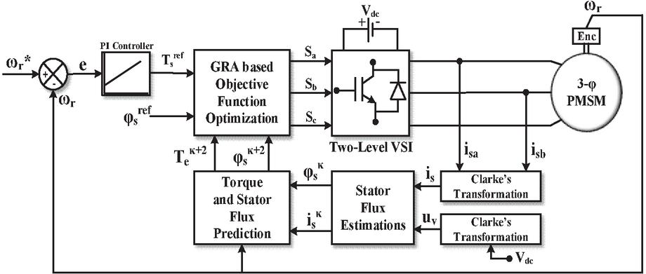
Figure 1 Control Structure of GRA based OF optimization for MPTC fed PMSM drive.
3 Implementation of GRA Based MPTC
The GRA approach is an proficient method for solving the models with inadequate information and complexity under discrete data. The predictions and estimations of the GRA based predictive torque control are similar to conventional MPTC. The objective-function optimization can be done by GRA based approach. The control structure for GRA based approach for PMSM drive is shown Figure 1. To begin, a dataset is created relying on the possible alternative solutions and necessary criteria. The collected dataset is validated to 0-1 scale. GRC and GRG are calculated using this simplified data set. The optimization of GRG generates an optimal value. The necessary predictions and estimations of the GRA based control algorithms are similar to MPTC. The OF is to be optimized by GRA based approach. To improve the WC choice, the existing OF is divided into two OFs analogous to stator flux () and torque () as given by Equations (5) and (6).
| (5) | ||
| (6) |
The implementation steps for GRA based MPTC approach for OF optimization is shown below in detail.
Step 1: Generation of dataset: The required dataset () for GRA approach can be attained from Equations (5) and (6)
| (7) |
Step 2: Dataset normalization: Dataset () is normalised to a scale of zero to one by means of Equations (8) and (9).
| (8) | ||
| (9) |
Where
Step 3: Identification of Grey Relational Coefficient (GRC): For Minimization of ripples, normalization dependent on cost criteria is used and the reference sequences for and T variables can be given by Equations (10) and (11)
| (10) | ||
| (11) |
for attaining the reference sequence required. GRC’s are estimated for and T reference sequences to attain the respective optimum alternatives. (coefficient distinguishing) is chosen to be 0.5.
| (12) | ||
| (13) |
Where
Step 4: Identification of Grey Relational Grade (GRG): By allocating the necessary weights, a GRG () is computed to acquire the mean correlation among GRC’s of and T and it is specified as
| (14) |
Where and are the weights given to GRC’s and T and the collective weight must satisfy as . By maximizing the GRG, optimal state of switching is achieved.
| (15) |
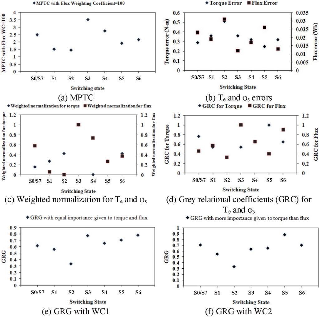
Figure 2 Selection of switching state in VSI for GRA based MPTC with two sets of WC.
Two sets of WC are selected for flux () and torque (T) in weighted normalization i.e WC1 with equal significance and WC2 with torque having greater significance using pair-wise comparison rules. Figure 2(a–f) shows the graphical representation for selecting the optimum switching instant of VSI for one periodic sample. Figure 2a shows that S is chosen as the optimum switching instant which gives second highest T and lowest errors for MPTC with flux WC 100. Figure 2b shows the T and errors; it is observed that S gives lowest T error, S gives lowest error and S gives highest errors for both T and . Figure 2c indicates the weighted normalized values for T, with WC1 and WC2. It is observed that S gives lowest T error, S gives lowest error. Figure 2d shows the GRC for both T and error terms. From this Fig., it can be observed that grey relational coefficient of toque is equal to 1 for switching state S and grey relational coefficient of stator flux is equal to 1 for switching state S. Hence, switching states S and S are the individual best alternatives for T and respectively. Figure 2e shows the GRG obtained for GRA based PTC with WC1. In this, switching state S gives maximum value for the GRG. Hence, switching state S is chosen as optimal control action for next sampling period. Figure 2f shows the GRG for GRA based PTC with WC2. In this, switching state S gives maximum value for the GRG. Hence, switching state S is chosen as optimal control action for next sampling period. The numerical values for OF of MPTC, GRCs and GRG values of proposed GRA based PTC with two sets of WC for all admissible switching states of the converter are presented in Table 1. In accordance with T and errors, the order of preference for choosing the switching instants of VSI are predicted as SSSSS/SSS for MPTC, SSSSS/SSS for GRA based MPTC with (WC1:) and SS/SSSSSS for GRA based MPTC with (WC2: , ). The implementation steps of GRA based PTC for PMSM drive is given below.
Step 1: Calculate i, V and
Step 2: Apply S
Step 3: Estimation of
Step 4: For different switching states i.e j 0,1,2…6, Prediction of T and
Step 5: Obtain G and G
Step 6: Dataset is to be generated and normalized
Step 7: GRC is to be obtained
Step 8: GRG is to be obtained
Step 9: Obtain S
Table 1 Selection of switching state for MPTC and GRA based PTC
| Switching | PTC Based on GRA | PTC Based on GRA | |||||||
| State | Errors | MPTC | WC1: | WC2:, | |||||
| of VSI | G | G | |||||||
| S/S | 0.29 | 0.023 | 2.5900 | 0.7647 | 0.4634 | 0.6141 | 0.7647 | 0.4634 | 0.7044 |
| S | 0.36 | 0.019 | 2.2600 | 0.5417 | 0.5758 | 0.5588 | 0.5417 | 0.5758 | 0.5485 |
| S | 0.51 | 0.031 | 3.6100 | 0.3333 | 0.3333 | 0.3333 | 0.3333 | 0.3333 | 0.3333 |
| S | 0.36 | 0.012 | 1.5600 | 0.5417 | 1.0000 | 0.7709 | 0.5417 | 1.0000 | 0.6333 |
| S | 0.32 | 0.017 | 2.0200 | 0.6500 | 0.6552 | 0.6526 | 0.6500 | 0.6552 | 0.6510 |
| S | 0.25 | 0.026 | 2.8500 | 1.0000 | 0.4043 | 0.7022 | 1.0000 | 0.4043 | 0.8808 |
| S | 0.32 | 0.013 | 1.6200 | 0.6500 | 0.9048 | 0.7774 | 0.6500 | 0.9048 | 0.7009 |
4 Hardware Results and Discussions
The dSPACE-DS1104 R&D controller board is used for real-time implementation of conventional and proposed control algorithms. The block diagram of this controller board is shown in Figure 3a. The main components of this controller board are main/master processor (MPC8240, PowerPC 603 core, 250 MHz), four multiplexed ADCs (16-bit), four independent ADCs (12-bit), eight DACs (16-bit), two incremental encoder interfaces, 20-bit digital I/Os, serial interface (RS232, RS485 and RS442) and one slave DSP (TMS320F240) with built-in PWM signals for both three-phase and single-phase PWM outputs. This controller board is placed in the 32-bit PCI slot of the personal computer (PC) and it requires MATLAB/SIMULINK/RTW as a prerequisite. To implement control algorithm in a digital platform, initially it has to be developed in MATLAB/SIMULINK environment. In order to communicate SIMULINK based control algorithm with PMSM drive, it is necessary to introduce I/O interfaces into the model using dSPACE real-time interfacing (RTI) blocks. This will allow the simulation to interface with the hardware. The two-level VSI used to drive the PMSM contains an inbuilt three-phase diode bridge rectifier and intermediate DC link capacitors. The DC supplies of 15 V are used for current sensors and voltage sensor and a DC supply of 10 V is used for incremental encoder. Figure 3b represents the setup for real time implementation of all algorithms.
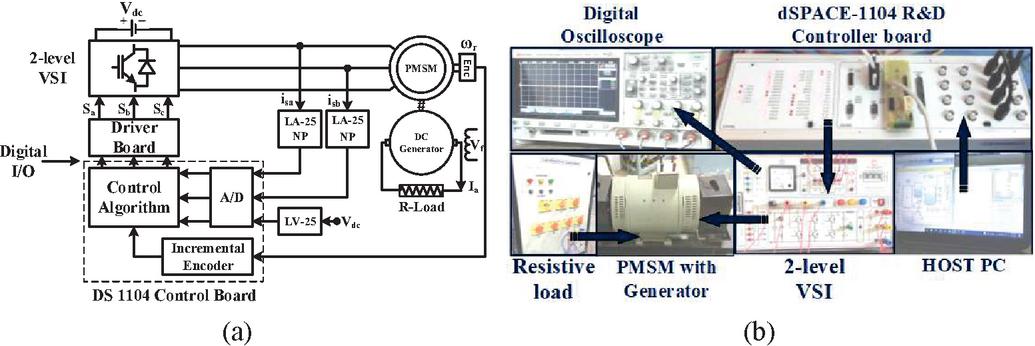
Figure 3 Model Predictive torque control: (a) Block diagram (b) Experimental set-up for PMSM drive.
4.1 Steady State Response of the Motor Drive in Real Time
Initially, PMSM is tend to operate at rated speed i.e., 150 rad/sec at 12 Nm loading condition Figure 4(a–d) represents the real time response of the drive for all control algorithms i.e., DTFC, MPTC, GRA with WC1&WC2. The responses of motor parameters are captured for developed torque (scaling 10N-m/div), mechanical speed (scaling 100rad/sec/div), stator phase current (scaling 5A/div) and stator flux (scaling 2Wb/div). Under steady state the ripples of torque, flux and %THD are calculated by taking the number of samples to be 4500. In DTFC: T, ripples and % THD are 10.1%, 3.01%, 7.13% respectively. In MPTC: T, ripples and % THD are 8.35%, 2.82% and 6.58% respectively. In GRA with WC1: T, ripples and % THD are 7.59%, 2.78% and 5.97% respectively. In GRA with WC2: T, ripples and % THD are 7.38%, 2.86% and 5.52% respectively.
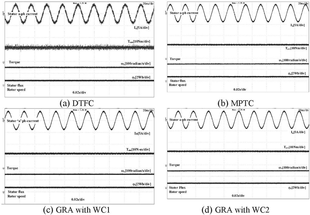
Figure 4 Response at 150radian/s and 12N-m load.
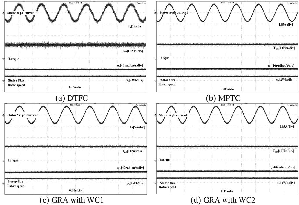
Figure 5 Response at 40radian/s and 12N-m load.
Similarly, PMSM is also tended to operate at low speed i.e., 40 rad/sec at 12 Nm loading condition Figure 5(a–d) represents the real time response of the drive for all control algorithms i.e., DTFC, MPTC, GRA with WC1&WC2. The responses of motor parameters are captured for developed torque (scaling 10N-m/div), mechanical speed (scaling 100rad/sec/div), stator phase current (scaling 5A/div) and stator flux (scaling 2Wb/div). Under steady state the ripples of torque, flux and %THD are calculated by taking the number of samples to be 4500. In DTFC: T, ripples and % THD are 11.14%, 2.82%, 7.91% respectively. In MPTC: T, ripples and % THD are 10.31%, 2.64% and 7.22% respectively. In GRA with WC1: T, ripples and % THD are 9.53%, 2.61% and 6.88% respectively. In GRA with WC2: T, ripples and % THD are 9.35%, 2.66% and 6.42% respectively. Table II indicates the comparison of steady state results for DTFC, MPTC and GRA with WC1&WC2 for a speed of 150 rad/sec and 40 rad/sec at loading of 12 Nm. From the comparison, it can be observed that steady state torque ripples and total harmonic distortion is low for GRA with WC2 and steady state flux ripple are low for GRA with WC1 at high and low speeds. All the lowest values of ripples in both the cases are shown with bold entities in Table 2.
Table 2 Comparison of steady state results for DTFC, MPTC and GRA with WC1&WC2
| Load | %T | % | ||||
| (Speed) | Torque | Control Algorithm | Ripple | Ripple | %THD | |
| 150 rad/sec | 12N-m | Conventional DTFC | 10.1% | 3.01% | 7.13% | |
| MPTC | 8.35% | 2.82% | 6.58% | |||
| GRA based | 7.59% | 2.78% | 5.97% | |||
| PTC | , | 7.38% | 2.86% | 5.52% | ||
| 40 rad/sec | 12N-m | Conventional DTFC | 11.14% | 2.82% | 7.91% | |
| MPTC | 10.31% | 2.64% | 7.22% | |||
| GRA based | 9.53% | 2.61% | 6.88% | |||
| PTC | , | 9.35% | 2.66% | 6.42% | ||
4.2 Dynamic Response of PMSM Drive in Real Time
Experiments are also conducted on the developed hardware for PMSM drive under dynamic state i.e., speed dynamics and torque dynamics. Figure 6(a–c) indicates the experimental results while the motor is undergoing speed dynamics keeping the load to be unchanged. Responses are extracted for MPTC and GRA with WC1 & WC2. To study the drive response during speed dynamics, motor has undergone change in speed i.e., 150 radian/s to 80 radian/s and from 80 radian/s to 120 radian/s at different instants of time, keeping the load to be unchanged at 12 Nm. The responses of motor parameters are captured for developed torque (scaling 10N-m/div), mechanical speed (scaling 100rad/sec/div), stator phase current (scaling 5A/div) and stator flux (scaling 2Wb/div).
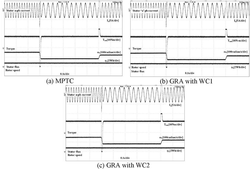
Figure 6 Speed dynamic responses of PMSM drive.
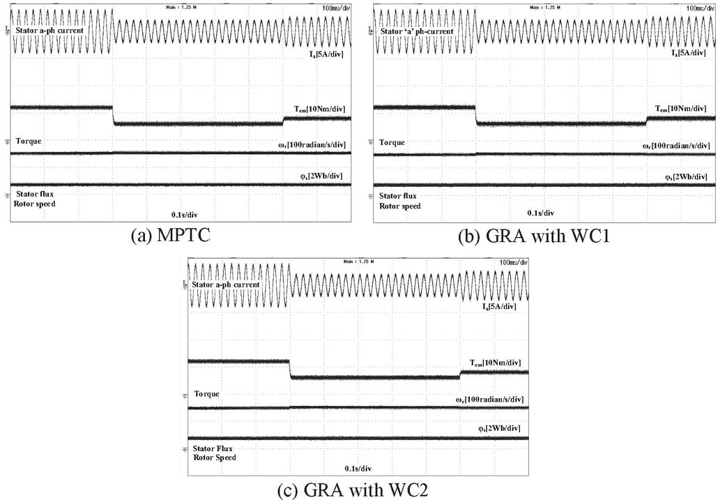
Figure 7 Torque dynamic responses of PMSM drive.
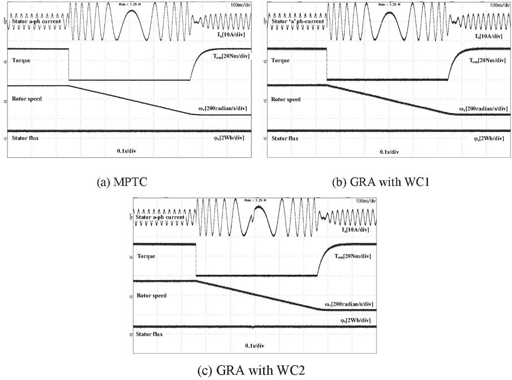
Figure 8 Response under speed reversals for PMSM drive.
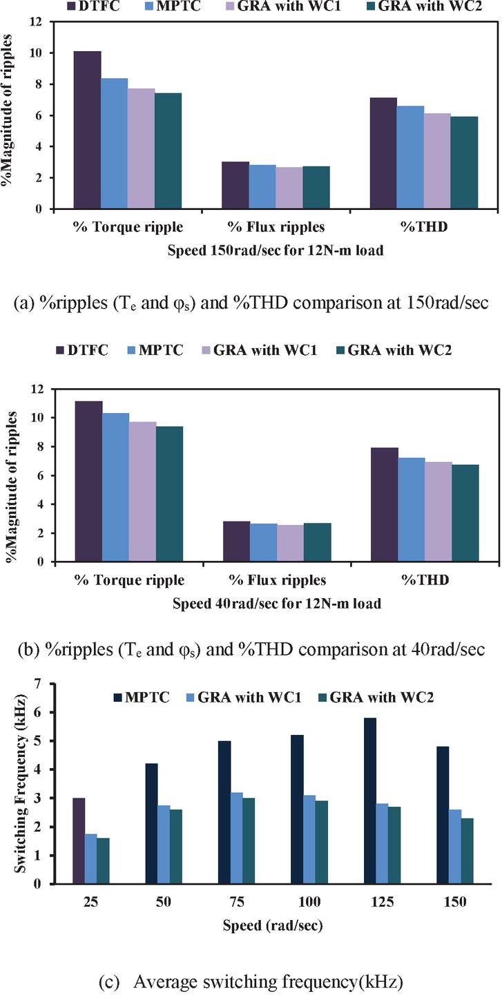
Figure 9 Comparative analysis of ripples and average switching frequency.
Figure 7a–c indicates the experimental results while the motor is undergoing torque dynamics keeping the speed to be unchanged. Responses are extracted for MPTC and GRA with WC1 & WC2. To study the drive response during torque dynamics, motor has undergone change in load i.e., 12Nm to 6Nm and from 6Nm to 8Nm at different instants of time, keeping the speed to be unchanged at 150radian/s. The responses of motor parameters are captured for developed torque (scaling 10N-m/div), mechanical speed (scaling 100rad/sec/div), stator phase current (scaling 5A/div) and stator flux (scaling 2Wb/div). From Figures 6 and 7, it can be observed that for GRA with WC2 the torque and flux profiles are improved.
4.3 Speed Reversals Response of PMSM Drive Real Time
Experiments are also conducted on the developed hardware for PMSM drive under reversals of speed. Figure 8(a–c) indicates the experimental results while the motor is undergoing speed reversals keeping the load to be unchanged. Responses are extracted for MPTC and GRA with WC1 & WC2. To study the drive response during speed reversals, motor has undergone change in speed i.e., 150 radian/s to 150 radian/s at different instants of time, keeping the load to be unchanged at 12 Nm. The responses of motor parameters are captured for developed torque (scaling 20N-m/div), mechanical speed (scaling 200rad/sec/div), stator phase current (scaling 10A/div) and stator flux (scaling 2Wb/div).
5 Comparative Analysis
Experiments are conducted on the developed hardware for PMSM drive under steady state for two different operating speed i.e., 150 radian/s and 40 radian/s at an unchanged load of 12Nm. Thereby calculated the ripples in flux, torque and %THD for DTFC, MPTC and GRA with WC1&WC2 as tabulated in Table 2. Figure 9(a–b) shows the graphical representation of steady state response for all the control algorithms. Figure 9c represents the graphical representation of average switching frequency under different speed of operations. From Figure 9, it could be observed that GRA with WC2 gives improved experimental responses compared to DTFC and MPTC.
6 Conclusion
In PMSM applications, MPTC offers a undeniable substitute for traditional control methods. With this approach, choice of best switching instant for each sampling duration is achievable using online optimization based on objective functions. However, identifying the suitable WC for the objective function is a tedious and heuristic process. To address this issue, the GRA approach is added to OF optimization to make the identification of WC simpler. It may also be simply expanded to any number of control variables in the objective function. GRC are computed based on the normalized values in order to obtain the individual optimal switching instants for control parameters (T and ). A distinguishing coefficient is used to expand or compress the range of GRC. A relative significance among control parameters in the GRG is simply chosen relying on pair-wise comparison rules. An optimal switching instant can be attained for next sample by maximizing the GRG. Experiments are conducted on the developed hardware using dSPACE-DS1104 R&D controller board for PMSM drive under steady state and dynamic state for DTFC, MPTC and GRA with WC1 & WC2. Responses declare that GRA with WC2 gives improved responses both in steady & dynamic states and can be replaced as a generic algorithm for performance improvement of PMSM drive.
Conflict of Interest
The authors declare no potential conflict of interest.
Appendix A
Specifications of PMSM: Rated speed (N) is 1500 rpm, Inductance of Stator (L) is 10.5 mH, Resistance of Stator (R) is 1.12, Permanent magnet flux () is 0.71 Wb, 2-pole pairs, Moment of inertia (J) is 0.0055 kg-m, 24 N-m of rated torque, DC link Voltage is 415V, and sampling time is 50 sec.
References
[1] R. Pothuraju, R. Tejavathu, A. K. Panda, ‘Multilevel Inverter fed Direct Torque and Flux Control-Space Vector Modulation of Speed Sensorless Permanent Magnet Synchronous Motor drive with Improved Steady State and Dynamic Characteristics’, International Journal of Circuit Theory and Application. 1–18; 2022.
[2] C. Qu, Z. Ge, C. Yang, and X. Wang, “Optimization and Simulation of Auxiliary Magnetic Barrier Permanent Magnet Synchronous Machine for Wind Turbine”, DGAEJ, vol. 37, no. 3, pp. 501–524, Dec. 2021.
[3] A. Vujji and R. Dahiya, “Speed Estimator for Direct Torque and Flux Control of PMSM Drive using MRAC based on Rotor flux,” 2020 IEEE 9th Power India International Conference (PIICON), 2020, pp. 1–6, doi: 10.1109/PIICON49524.2020.9113030.
[4] P. D. Kumar & R. Tejavathu, ‘Investigation of Torque Ripple Behaviour for Five-Level Inverter-Fed Modified Model Predictive Torque Control-Based PMSM Drive’, IETE Technical Review, 2022.
[5] K. Eshwar, K. M. Ravi Eswar, & T. V. Kumar, ‘An effective predictive torque control scheme for PMSM drive without involvement of weighting factors’, IEEE Journal of Emerging and Selected Topics in Power Electronics, 9(3), 2685–2697, 2020.
[6] I. Benhamida, A. Ameur, K. Kouzi, et al., ‘Torque Ripple Minimization in Predictive Torque Control Method of PMSM Drive Using Adaptive Fuzzy Logic Modulator and EKF Estimator’, J Control Autom Electr Syst 30, 1007–1018, 2019.
[7] M. B. Tirumalasetti; U. B. Manthati, P. Srinivas, C. R. Arunkumar, “A Novel Predictive Control Scheme for Interleaved Buck Converter in Low Power Applications”, DGAEJ, 37, 609–630, 2022.
[8] M. A. Husain, R. Rajput, M. K. Gupta, M. Tabrez, M. W. Ahmad, and F. I. Bakhsh, “Design and Implementation of Different Drive Topologies for Control of Induction Motor for Electric Vehicle Application”, DGAEJ, vol. 37, no. 4, pp. 999–1026, Apr. 2022.
[9] A. Vujji and R. Dahiya, “Design of PI Controller for Space Vector Modulation based Direct Flux and Torque Control of PMSM Drive,” 2020 First IEEE International Conference on Measurement, Instrumentation, Control and Automation(ICMICA),2020, pp. 1–6, doi: 10.1109/ICMICA48462.2020.9242812.
[10] A. Rojas, J. Rodriguez, F. Villarroel, J. Espinoza, and D. A. Khaburi, ‘Multi objective fuzzy predictive torque control of an induction motor drive’, in Proc. 6th Power Electron., Drive Syst. Technol. Conf., pp. 201–206, 2015.
[11] E. Kusuma, & V. K. Thippiripati, ‘Effective predictive torque control scheme for four-level open-end winding permanent magnet synchronous motor drive’, International Transactions on Electrical Energy Systems, 30(10), e12536, 2020.
[12] C. A. Rojas, J. Rodriguez, F. Villarroel, J. R. Espinoza, C. A. Silva, and M. Trincado, ‘Predictive torque and flux control without weighting factors’, IEEE Trans. Ind. Electron., vol. 60, no. 2, pp. 681–690, 2013.
[13] V. P. Muddineni, A.K. Bonala, and S. R. Sandepudi, ‘Enhanced weighting factor selection for predictive torque control of induction motor drive based on VIKOR method’, IET Electr. Power Appl., vol. 10, no. 9, pp. 877–888, 2016.
[14] A. Vujji, & R. Dahiya, ‘Experimental Evaluation of VIKOR-Based Cost Function Optimization of Finite Control Set-Predictive Torque Control for Permanent Magnet Synchronous Motor Drive’, Journal of Failure Analysis and Prevention, 1–16, 2022.
[15] V. P. Muddineni, A. K. Bonala and S. R. Sandepudi, ‘Grey relational analysis -based objective function optimization for predictive torque control of induction machine’, IEEE Transactions on Industry Applications, 57(1), pp. 835–844, 2020.
[16] V. P. Muddineni, S. R. Sandepudi, & A. K. Bonala, ‘Improved weighting factor selection for predictive torque control of induction motor drive based on a simple additive weighting method’, Electric Power Components and Systems, 45(13), 1450–1462, 2017.
[17] A. Vujji, R. Dahiya, Real-Time Implementation for Improvement of Weighting Coefficient Selection using Weighted Sum Method for Predictive Torque Control of PMSM Drive. Arab J Sci Eng, https://doi.org/10.1007/s13369-022-07430-z, 2022.
[18] C. A. Rojas, J. R. Rodriguez, S. Kouro, and F. Villarroel, ‘Multiobjective fuzzy-decision-making predictive torque control for an induction motor drive’, IEEE Trans. Power Electron., vol. 32, no. 8, pp. 6245–6260, 2017.
[19] P. R. U. Guazzelli, W. C. de Andrade Pereira, C. M. R. de Oliveira, A. G. de Castro, and M. L. de Aguiar, ‘Weighting factors optimization of predictive torque control of induction motor by multiobjective genetic algorithm’, IEEE Trans. Power Electron., vol. 34, no. 7, pp. 6628–6638, 2019.
[20] M. Siami, D. A. Khaburi and J. Rodriguez, ‘Simplified finite control set-model predictive control for matrix converter-fed PMSM drives’, IEEE Trans. Power Electron., vol. 33, no. 3, pp. 2438–2446, 2018.
[21] Y. Zhang and H. Yang, ‘Model-predictive flux control of induction motor drives with switching instant optimization’, IEEE Trans. Energy Convers., vol. 30, no. 3, pp. 1113–1122, 2015.
[22] Y. Zhang and H. Yang, ‘Two-vector-based model predictive torque control without weighting factors for induction motor drives’, IEEE Trans. Power Electron., vol. 31, no. 2, pp. 1381–1390, 2016.
[23] P. Chen, T. Pan & S. Chen, ‘Development of Double Closed-loop Vector Control Using Model Predictive Control for Permanent Magnet Synchronous Motor’, J Control Autom Electr Syst 32, 774–785, 2021.
[24] Z. Chen, J. Qiu, and M. Jin, ‘Adaptive finite-control-set model predictive current control for IPMSM drives with inductance variation’, IET Electr. Power Appl., vol. 11, no. 5, pp. 874–884, 2017.
[25] Z. Lu, R. Zhang, L. Hu, L. Gan, J. Lin, and P. Gong, ‘Model predictive control of induction motor based on amplitude-phase motion equation’, IET Power Electron., vol. 12, no. 9, pp. 2400–2406, 2019.
[26] J. F. Stumper, V. Hagenmeyer, S. Kuehl, and R. Kennel, ‘Deadbeat control for electrical drives: A robust and performant design based on differential flatness’, IEEE Trans. Power Electron., vol. 30, no. 8, pp. 4585–4596, 2015.
[27] P. Cortes et al., ‘Guidelines for weighting factors design in model predictive control of power converters and drives’, Proc. IEEE Int. Conf. Ind. Technol., pp. 1–7, 2009.
[28] S. Thielemans, J. Melkebeek, and T. J. Vyncke, ‘Weight factor selection for model-based predictive control of a four-level flying-capacitor inverter’, IET Power Electron., vol. 5, no. 3, pp. 323–333, 2012.
[29] S. A. Davari, D. A. Khaburi, and R. Kennel, ‘An improved FCS-MPC algorithm for an induction motor with an imposed optimized weighting factor’, IEEE Trans. Power Electron., vol. 27, no. 3, pp. 1540–1551, 2012.
[30] F. Villarroel, J. R. Espinoza, C. A. Rojas, J. Rodriguez, M. Rivera, and D. Sbarbaro, ‘Multiobjective switching state selector for finite-states model predictive control based on fuzzy decision making in a matrix converter’, IEEE Trans. Ind. Electron., vol. 60, no. 2, pp. 589–599, 2013.
[31] O. Machado, F. J. Rodriguez, E. J. Bueno, and P. Martin, ‘A neural network-based dynamic cost function for the implementation of a predictive current controller’, IEEE Trans. Ind. Informat., vol. 13, no. 6, pp. 2946–2955, 2017.
[32] A. Bhowate, M. Aware, and S. Sharma, ‘Predictive torque control with online weighting factor computation technique to improve performance of induction motor drive in low speed region’, IEEE Access, vol. 7, pp. 42309–42321, 2019.
[33] M. Velasquez, and P. T. Hester, ‘An Analysis of Multi-Criteria Decision Making Methods’, Int. J. Oper. Res., vol. 10, no. 2, pp. 56–66, 2013.
[34] K. S. Prasad, S. R. Chalamalasetti, and N. R. Damera, ‘Application of grey relational analysis for optimizing weld bead geometry parameters of pulsed current micro plasma arc welded Inconel 625 sheets’, Int. J. Adv. Manuf. Technol., vol. 78, nos. 1–4, pp. 625–632, 2014.
[35] M. H. Arshad, M. A. Abido, A. Salem and A. H. Elsayed, ‘Weighting factors optimization of model predictive torque control of induction motor using NSGA-II with TOPSIS decision making’, IEEE Access, vol. 7, pp. 177595–177606, 2019.
Biographies

Avinash Vujji received the B.Tech degree in electrical and electronics engineering from Jawaharlal Nehru Technological University, Hyderabad, India, in 2008, the M.Tech degree in power and industrial drives from Jawaharlal Nehru Technological University, Kakinada, India, in 2013. Presently doing research for Ph.D degree in the department of electrical engineering, National Institute of Technology (NIT), Kurukshetra, India. His research interests include power electronics, control of electrical drives.

Ratna Dahiya received the BE degree in electrical engineering from G B Pant University, Pantnagar, Nainital, Uttar Pradesh, India, in 1982, the M.Tech degree from the REC (National Institute of Technology (NIT)) Kurukshetra, India, in 1985, and the Ph.D degree from the Kurukshetra University, Kurukshetra, India, in 2002. Currently, she is a Professor in the Department of Electrical Engineering, NIT Kurukshetra. Her research interests include power electronics, control of electrical drives power system, FACTs and electrical power distribution system.
Distributed Generation & Alternative Energy Journal, Vol. 38_5, 1433–1454.
doi: 10.13052/dgaej2156-3306.3854
© 2023 River Publishers