Performance Investigation of Grid Connected DFIG Based Wind Energy System
Bisma Hamid*, Sheikh Javed Iqbal and Ikhlaq Hussain
Department of Electrical Engineering, NIT Srinagar, India
E-mail: bismahamid@gmail.com; jvd@nitsri.net; ikhlaq@nitsri.net
*Corresponding Author
Received 15 January 2022; Accepted 03 April 2022; Publication 09 December 2022
Abstract
The paper realizes the investigation of control operation and performance in grid integrated Doubly Fed Induction Generator (DFIG) system. Battery Energy Storage (BES), coupled at the DC link of DFIG is controlled by bidirectional power converter to compensate for utility/load demand. Rotor side converter (RSC) uses tip-speed ratio maximum power point tracking (MPPT) algorithm to harness maximum power from the wind turbine. An adjustable step size least mean square (LMS) based adaptive control is implemented for the grid side converter (GSC) of DFIG system that besides managing power balance at the Point of Common Coupling (PCC) also addresses power quality issues encountered in the system due to the presence of non-linear, unbalanced loads. The step size changes with the mean square error enabling the adaptive filter to detect system changes while producing a small steady state error. Performance of the system is exhibited and validated through simulated results in a developed Simulink model for steady state and dynamic conditions. The Total Harmonic Distortion (THD) in grid currents and voltage is within IEEE 519 standard guidelines.
Keywords: Battery energy storage, bidirectional converter, doubly fed induction generator, power quality, power electronics, wind energy conversion system.
1 Introduction
The electric power generation has emanated as the primary application of wind energy across the globe. Economic growth, technological breakthroughs, expanding population and environmental concerns have all contributed to a considerable increase in wind power penetration. Consequently, the control of wind energy conversion systems to endorse system stability and power quality in the connected system is an absolute necessity. Wind turbines with variable speeds have come a long way in recent years. The variable speed wind turbines employing Doubly Fed Induction Generator (DFIG) topology are gaining popularity with advanced power electronics and control systems due to increased energy capture, higher stability, decoupled control of active and reactive power, lower mechanical stresses and enhanced power quality [1–3]. The stochastic nature of wind energy source, however, continues to pose issues for smooth grid integration and in this aspect, energy storage is a potential option. The incorporation of energy storage emphasises the efficient use of wind energy for high-quality and reliable electricity [4, 5].
Integrating an energy storage device with a wind energy system to reduce wind generation uncertainty will improve grid dependability and security. Various energy storage systems (ESS) have been used with DFIG-based wind energy systems based on their operating suitability over various time spans. The flywheel energy storage offers a boost of power in the event of low wind generation and stores surplus power during high wind generation with a fuzzy logic-based supervisor to deal with uncertain wind power [6]. Super-capacitor energy storage has been employed to successfully minimise the issue of power fluctuations and improve FRT capability of DFIG system [7]. The author in [8] focuses on a new SMES with fault current limitation function (SMES-FCL) setup and optimization technique for boosting LVRT capabilities and mitigating power fluctuation of DFIG wind energy system. However, BES is still gaining traction as one of the key solutions for integrating large scale of wind energy into the power systems both in low and high power applications. As batteries are expensive and considerably increase system expenditure and maintenance, a control approach is critical for optimising BES utilisation and, as a result, lowering its capacity and investment [9, 10]. The vector control strategy finds wide application in control of DFIG converters. S Puchalapalli [11], Naidu [12] and Tourou [13] used BES for DFIG systems to achieve grid power smoothing and voltage and frequency regulation for standalone operation. However, the BES was integrated to the DC link without any control. Many conventional control schemes operating on instantaneous reactive power theory [14], enhanced phase locked loop [15], synchronous reference frame theory [16], reduced-order multiple integrator (ROMI) [17] have been utilised for the control of grid interfaced converters.
The vector control approach is mainly used in DFIG wind energy systems to execute converter control as reported in [18–21]. Contrary to vector control strategy, adaptive control has rarely been investigated for DFIG systems particularly in the context of power quality enhancement. In such a control, the error between the desired output and output obtained is minimized based on the mean square error. The error as a cost function is optimised to the smallest possible value by an algorithm that continuously alter its weights until the intended output is obtained [22]. In this paper, a grid connected DFIG system along BES has been modelled to examine the control and operation of the system for grid power regulation and power quality mitigation challenges. The main objectives of the paper are as follows:
(i) Maximize power capture from the DFIG wind energy system under variable wind speed employing MPPT algorithm.
(ii) Implementation of variable step size least mean square (LMS) based adaptive control for GSC of DFIG system to maintain power balance in the system and address power quality issues emerging from harmonics, unbalanced load and other grid disturbances.
(iii) Integration of BES at the DC link of the system that acts as a standby supply to compensate for the utility/load demand.
(iv) To evaluate controller performance under steady state condition, variable wind speed, non-linear unbalanced loads and during other dynamic conditions.
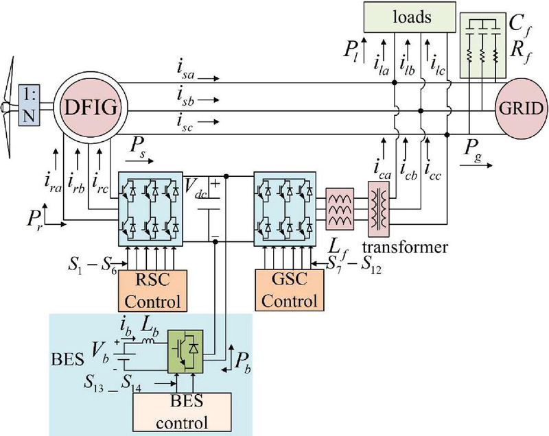
Figure 1 Schematic diagram of proposed grid tied DFIG system.
Table 1 Specifications of proposed grid connected DFIG wind turbine
| Parameter | Rating | Parameter | Rating |
| Wind turbine | 11 kW | Transformer | 10 kVA |
| Rotor diameter | 4.34 m | Interfacing inductors L | 1.135 mH |
| Air density | 1.1514 kg/m | Ripple filter | R, C F |
| Gear-box ratio | 16.84 | DC link voltage | 240 V |
| Rated wind speed | 9 m/s | Battery voltage V | 180 V |
| DFIG | 8.75 kW | Battery capacity | 360 Ah |
2 System Description
The schematic diagram of the proposed grid tied DFIG wind energy system is represented in Figure 1. The system constitutes of the wind turbine connected to generator shaft through a gearbox. The stator directly connects with the system of loads and the power grid while as machine rotor is assessed through power electronic converters that process about 25–30% of the rated power. A bidirectional DC-DC converter connects energy storage to the DC link of DFIG converters, keeping its operation within safe limits. A three phase transformer steps up the low rating voltage of converter system to the line voltage for operational compatibility of the system. Three phase interfacing inductor (L) and ripple filter (C, R) takes the edge of current and voltage ripples in the system. The design of each component of the system including wind turbine is reported in [23–25]. The ratings of various components of the proposed system is given in Table 1 above.
2.1 Wind Turbine Rating
The following equation determines the amount of power that can be extracted from the wind energy [26].
| (1) |
where V represents wind speed in (m/s), is air specific density in (kg/m), r is the radius of turbine in (m) and C is the power coefficient of the turbine. The coefficient of performance C is a function of tip speed ratio and blade pitch angle (deg). C is determined by the following set of equations.
| (2) | ||
| (3) |
The pitch angle in this study has been taken as zero degree.
3 Control Scheme
The entire control operation of the presented grid integrated DFIG wind energy conversion system is realized by the independent control of three different power electronic converters. Each converter is dedicated to its own control objectives for the rotor side, grid side and battery energy storage system. The detail of each control is presented in the following sub-sections.
3.1 RSC Control
RSC control is allocated to active and reactive power generation of DFIG machine. The vector control based on d-q reference frame with stator voltage positioned along d axis is used to execute the desired control by generating d and q axis rotor current references appropriately. The TSR MPPT algorithm is utilised to extract optimum power from the wind turbine. From the sensed wind speed and specified turbine parameters reference; a rotor speed is generated that is compared with sensed rotor speed to build direct axis rotor reference I after fixing the error by PI controller. The quadrature axis rotor current reference I is generated from DFIG parameters that considers reactive power requirement for machine magnetization. The rotor current references in d-q frame are transformed into natural frame references with the aid of transformation angle as shown in Figure 2. The rotor current references i and sensed rotor currents i are compared and the pulses for RSC are generated by the hysteresis current controller.
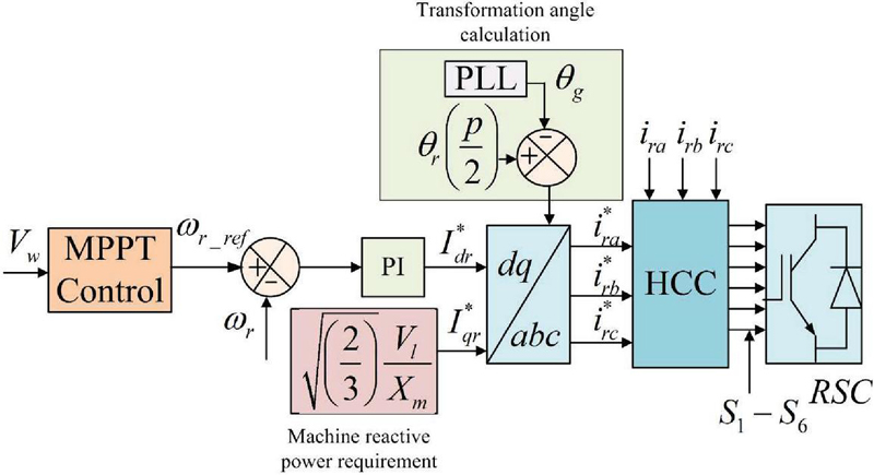
Figure 2 RSC control implementation.
3.2 GSC Control
The role of GSC control in grid integrated DFIG system is multifunctional. The controller in addition of regulating wind power to the connected network, addresses power quality issues prevalent in the system due to the presence of non-linear loads, reactive power requirement of loads, load unbalance and other grid disturbances. For this purpose, a single layer variable step size least mean square based adaptive filter has been employed for grid interfaced converter of DFIG system where the active load component weight is derived as shown in Figure 3 below. The active fundamental weight of load currents for each phase are calculated by following set of equations.
| (4) | |
| (5) | |
| (6) |
where w(k), u(k), e(k), i(k) and t(k) are the weight, in-phase unit vector templates, adaptive error, desired load components and step-size of each phase. , and are the constant values used for the determination of step size parameter adjusted suitably to obtain balance between rate of convergence and response of adaptive control.
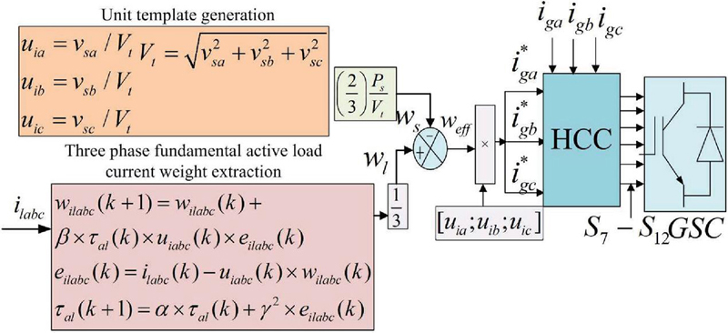
Figure 3 GSC control implementation.
The DFIG wind feed-forward term is estimated as.
| (7) |
where P is the power generated by DFIG machine and V is the magnitude of terminal voltage.
The effective weight concerning active reference component is given as.
| (8) |
where w is the weight of the load current components on average. The three phase active grid current reference are further calculated as.
| (9) |
The active grid current references i are compared with sensed grid currents i and the gating pulses for GSC are generated by the hysteresis current controller.
3.3 Battery Energy Storage Control
BES system constitutes of battery energy storage with bidirectional DC-DC converter. Depending on the operation of switches, the bidirectional converter can work in two modes: buck and boost. The converter comprises of an inductor L and two IGBT switches S and S with anti-parallel diodes D and D respectively as shown in Figure 4. The duty cycle of the switches is controlled for regulating amount of battery power exchange with the grid. The battery operation is controlled by employing a control loop that regulates the DC link voltage at a specified value. The reference V and measured DC link voltage V is compared; the resulting error is processed by a PI controller that determines the battery reference current i. In the inner control loop, i is compared with measured battery current i and the PI controller outputs reference signal of duty cycle which is compared with PWM generator to generate pulses for the converter switches. In cases, when battery is required to release energy, the bidirectional converter operates in boost mode with switch S and diode D functional thereby discharging the battery. In cases, when the generation from the wind energy source is more than that required to fulfil the demand the surplus power is diverted to the storage and henceforth the converter operates in buck mode with switch S and diode D functional there by battery charges. However, an additional limiter block is introduced in the control that operates the battery within safe limits to ensure its optimal performance. The peak battery current occurs when DFIG energy source generates maximum power with zero energy demand on AC side.
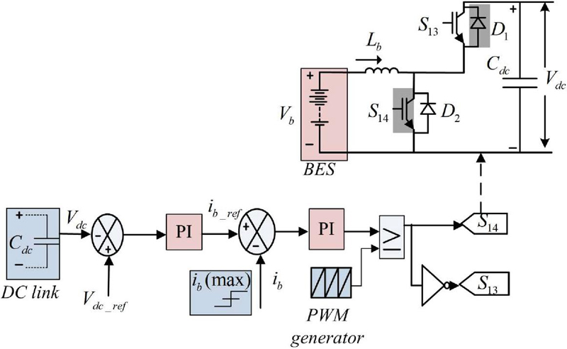
Figure 4 Bidirectional buck-boost control for BES.
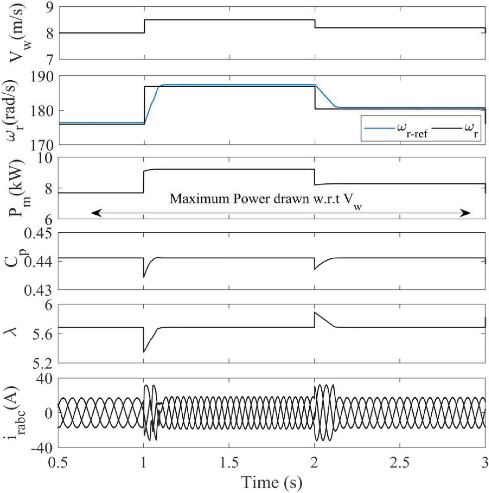
Figure 5 MPPT operation of grid tied DFIG system.
4 Results and Discussion
The proposed grid tied DFIG system along with associated control schemes for RSC, GSC and BES is designed in MATLAB software and the performance of the system is evaluated for different operating conditions as explained below.
4.1 MPPT Algorithm Operation of DFIG System
Figure 5 shows that the MPPT algorithm used in the RSC control of the DFIG system provides a suitable response. The rotor speed of the machine properly tracks the reference speed in accordance with the changing wind profile V. The amount of power produced by wind turbine P is at its maximum value depending on the variable speed. The power coefficient C and tip speed ratio of the turbine are at their optimal values irrespective of V variation. The frequency of rotor i is also seen changing with V that consequently maintains DFIG output at constant frequency as that of connected grid.
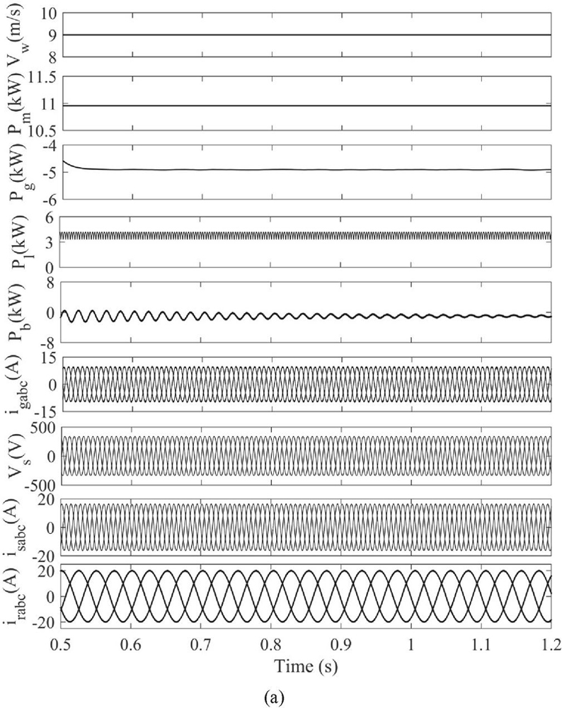
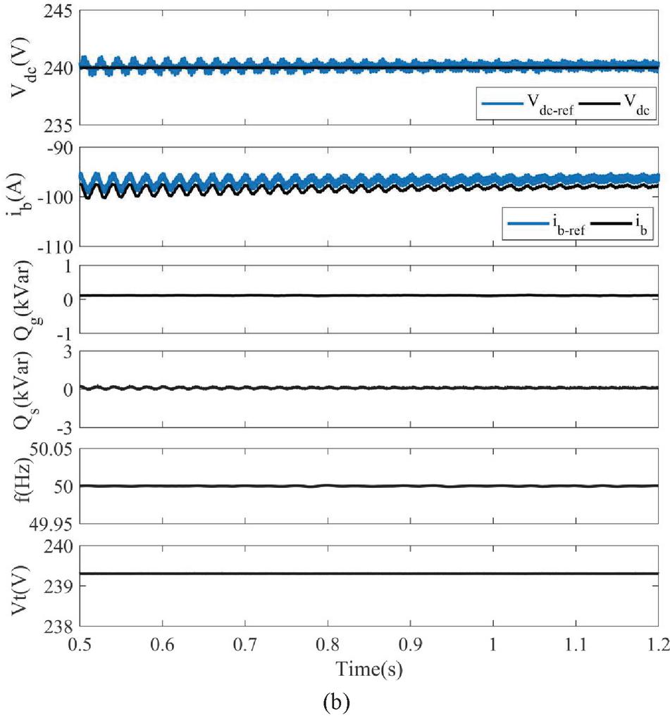
Figure 6 Performance of system at steady state (a) V, P, P, P, P, i, V, i and i (b) V, i, Q, Q, f and V.
4.2 Steady State Operation of DFIG System
At a rated wind speed of 9 m/s, the active power P generated by the DFIG wind turbine is around 11 kW with the wind energy source operating at maximum power point (MPP). The grid currents i, stator voltage V, stator currents i and rotor currents i are all sinusoidal and balanced as seen in Figure 6(a). The response of grid P and battery power P is also shown in figure. The system after feeding a load of P kW directs remaining power to the grid. The bidirectional converter control for the BES also depicts satisfactory performance by maintaining DC link voltage V at a predefined value of 240 V and tracking battery reference current i as shown in Figure 6(b). As illustrated in Figure 6, the system maintains unity power factor on both the grid and stator sides, with negligible reactive power consumption at both ends (Q Q 0). The terminal voltage V and frequency f at the connected grid are also maintained at their respective rated values as seen in figure.
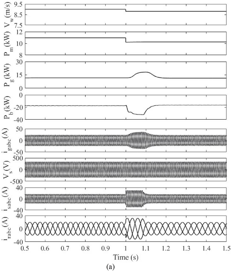
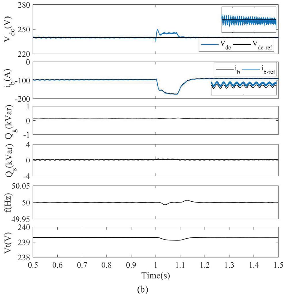
Figure 7 Performance of system at steady state (a) V, P, P, P, i, V, i and i (b) V, i, Q, Q, f and V.
4.3 System Operation During Wind Speed Variation
The performance of DFIG system under varying wind speed is shown in Figure 7(a–b). The wind turbine is also subjected to a step wind speed changeat the instant of t 1 s. The active power output P of the DFIG changes with variable V. However, irrespective of wind power generation, a fixed amount of power P is supplied to the grid as shown in Figure 7(a). The battery in this case compensates for any deviation in power to be supplied to the grid. BES either charges or discharges depending on the generation and demand from the grid and fed loads. The response of grid currents i, stator voltage V, stator currents i and rotor currents i with variable V is also shown in figure. DC link voltage controller although experiences transients due to sudden change in V but following that it again attains stable steady state value as shown in Figure 7(b). Unity power factor operation is maintained throughout the variation as seen in figure. The DFIG operates at different speeds and irrespective of this variation, the terminal voltage and frequency of the system remains equal to that of connected grid.
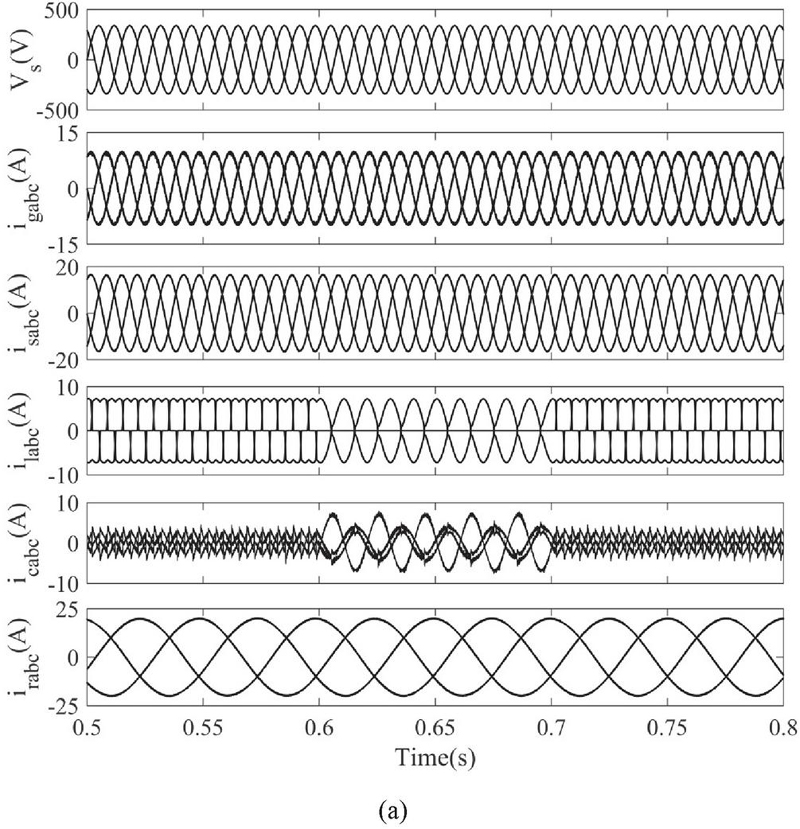
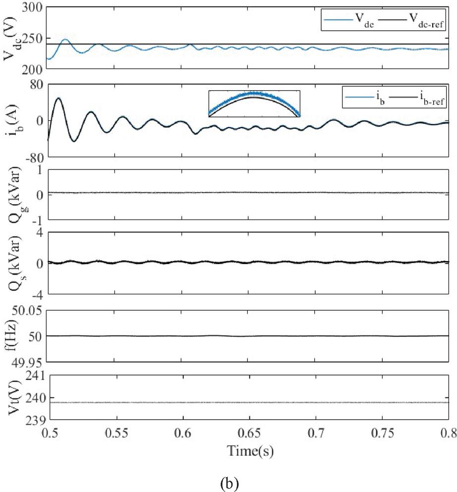
Figure 8 Performance of system at steady state (a) V, i, i, i, and i (b) V, i, Q, Q, f and V.
4.4 System Operation at Unbalanced Load
At the time instant from t 0.6 s to t 0.7 s, phase a of load is disconnected to create unbalance; such loads draw unbalanced currents from the source and affect system stability. GSC control compensates for the unbalanced load by supplying converter currents i that result in sinusoidal and balanced currents being drawn from the source as depicted in Figure 8(a). Also due to the presence of non-linear loads, harmonics are introduced in source i and grid currents i that can deteriorate system performance considerably. The presented variable step LMS based adaptive control executed for the GSC compensates for these harmonics and reduces total harmonic distortion (THD) in the currents. The response of V, i, i, load currents i, converter currents i and rotor currents i during unbalanced operation is shown in figure. GSC also considers reactive power requirement of load. Unity power factor is maintained throughout the operation with negligible Q and Q. The performance of BES controller executed in the system is intact with V maintained at defined value and i following i. V and f are also at their operating values as shown in Figure 8.
4.5 Frequency Spectrum of System Parameters
Figure 9(a–d) below demonstrates the total harmonic distortion (THD) in grid voltage V, grid current i, source current i and load current il. It can be seen that THD in grid current and voltage is within 5% that is in accordance with IEEE Standard limits.
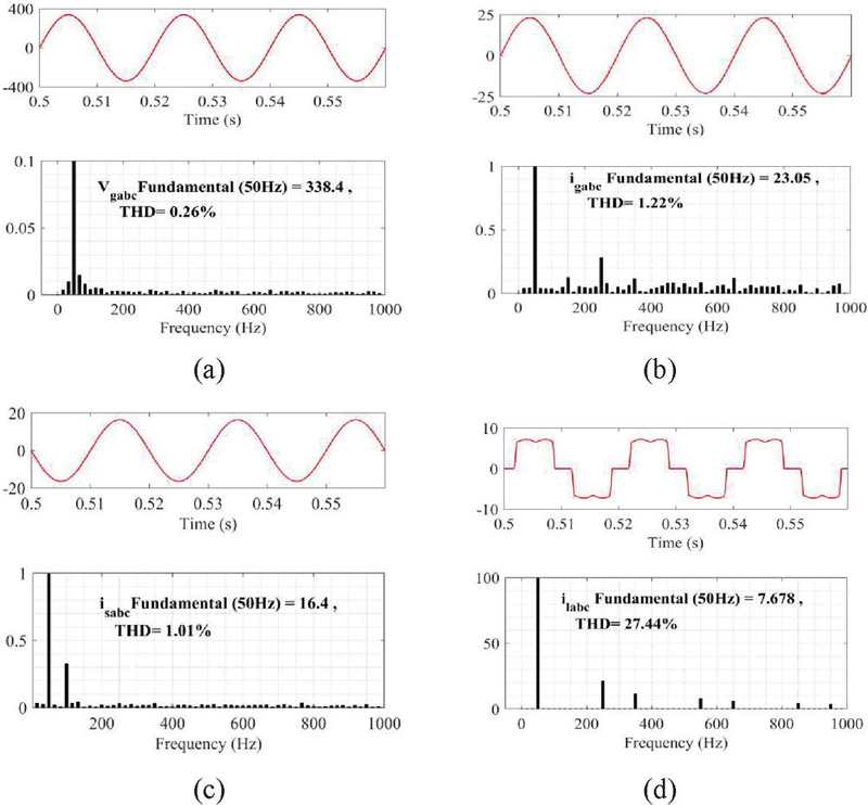
Figure 9 Frequency Spectrum of system parameters(a) V (b) i (c) i and (d) i.
5 Conclusion
This paper focuses on control operation of grid connected DFIG/BES based wind energy system. The peak power extraction is realized by employing tip speed ratio MPPT control. BES with bidirectional DC-DC converter control is used to regulate the grid power and address wind intermittency. A variable step size least mean square based adaptive control maintains quality power at both stator and grid side with unity power factor operation. The adaptive control also reduces system complexity by eliminating complex reference transformations for load current components. Simulated results depict satisfactory response of all the system parameters under changing operating conditions.
References
[1] J. M. Carrasco et al., “Power-electronic systems for the grid integration of renewable energy sources: A survey,” IEEE Trans. Ind. Electron., vol. 53, no. 4, pp. 1002–1016, 2006, doi: 10.1109/TIE.2006.878356.
[2] R. Pena, J. C. Clare, and G. M. Asher, “Doubly fed induction generator using back-to-back PWM converters and its application to variablespeed wind-energy generation,” IEE Proc. Electr. Power Appl., vol. 143, no. 3, pp. 231–241, 1996, doi: 10.1049/ip-epa:19960288.
[3] A. Kumar, V. M. Mishra, and R. Ranjan, “LVRT enhancement in grid connected DFIG based wind turbine using PSO optimized DVR,” Distrib. Gener. Altern. Energy J., vol. 35, no. 4, pp. 249–264, 2020, doi: 10.13052/dgaej2156-3306.3541.
[4] M. S. Lu, C. L. Chang, W. J. Lee, and L. Wang, “Combining the Wind Power Generation System With Energy Storage Equipment,” IEEE Trans. Ind. Appl., vol. 45, no. 6, pp. 2109–2115, 2009, doi: 10.1109/TIA.2009.2031937.
[5] P. H. A. Barra, W. C. de Carvalho, T. S. Menezes, R. A. S. Fernandes, and D. V. Coury, “A review on wind power smoothing using high-power energy storage systems,” Renew. Sustain. Energy Rev., vol. 137, no. April, p. 110455, 2021, doi: 10.1016/j.rser.2020.110455.
[6] M. Nadour, A. Essadki, and T. Nasser, “Power Smoothing Control of DFIG Based Wind Turbine using Flywheel Energy Storage System,” 2020 Int. Conf. Electr. Inf. Technol. ICEIT 2020, pp. 0–6, 2020, doi: 10.1109/ICEIT48248.2020.9113213.
[7] D. M. Yehia, “DFIG-Based Wind Turbine with Supercapacitor Energy Storage,” in IEEE International Conference Power & Energy (PECON), 2014, pp. 187–190.
[8] I. Ngamroo and T. Karaipoom, “Improving Low-Voltage Ride-Through Performance and Alleviating Power Fluctuation of DFIG Wind Turbine in DC Microgrid by Optimal SMES with Fault Current Limiting Function,” IEEE Trans. Appl. Supercond., vol. 24, no. 5, 2014, doi: 10.1109/TASC.2014.2333031.
[9] L. M. S. de Siqueira and W. Peng, “Control strategy to smooth wind power output using battery energy storage system: A review,” J. Energy Storage, vol. 35, no. December 2020, p. 102252, 2021, doi: 10.1016/j.est.2021.102252.
[10] X. Li, S. Member, D. Hui, and X. Lai, “Battery Energy Storage Station ( BESS ) -Based Smoothing Control of Photovoltaic ( PV ) and Wind Power Generation Fluctuations,” vol. 4, no. 2, pp. 464–473, 2013.
[11] S. Puchalapalli, B. Singh, S. K. Tiwari, and P. K. Goel, “Design and Analysis of Grid-Interactive DFIG Based WECS for Regulated Power Flow,” vol. 9994, no. c, pp. 1–11, 2020, doi: 10.1109/TIA.2020.3011059.
[12] N. K. S. Naidu and B. Singh, “Grid-Interfaced DFIG-Based Variable Speed Wind Energy Conversion System With Power Smoothening,” IEEE Trans. Sustain. Energy, vol. 8, no. 1, pp. 51–58, 2017, doi: 10.1109/TSTE.2016.2582520.
[13] P. Tourou, J. Chhor, K. Günther, and C. Sourkounis, “Energy storage integration in dfig-based wind energy conversion systems for improved fault ride-through capability,” 2017 6th Int. Conf. Renew. Energy Res. Appl. ICRERA 2017, vol. 2017-Janua, pp. 374–377, 2017, doi: 10.1109/ICRERA.2017.8191088.
[14] B. Singh, A. Adya, A. P. Mittal, and J. R. P. Gupta, “Modeling and control of DSTATCOM for three-phase, four-wire distribution systems,” Conf. Rec. – IAS Annu. Meet. (IEEE Ind. Appl. Soc., vol. 4, pp. 2428–2434, 2005, doi: 10.1109/IAS.2005.1518801.
[15] B. Singh and S. R. Arya, “Implementation of single-phase enhanced phase-locked loop-based control algorithm for three-phase DSTATCOM,” IEEE Trans. Power Deliv., vol. 28, no. 3, pp. 1516–1524, 2013, doi: 10.1109/TPWRD.2013.2257876.
[16] S. Yang, L. Zhan, C. Huang, and Z. Xie, “Unbalanced control system design for DFIG-based wind turbines,” Proc. - Power Eng. Autom. Conf. PEAM 2012, no. 1, pp. 3–6, 2012, doi: 10.1109/PEAM.2012.6612440.
[17] S. Bhattacharyya, S. Puchalapalli, and B. Singh, “Battery management and operation of a wind-PV based microgrid,” 2020 IEEE Int. Conf. Comput. Power Commun. Technol. GUCON 2020, pp. 423–429, 2020, doi: 10.1109/GUCON48875.2020.9231116.
[18] R. Hemmati, H. Faraji, and N. Y. Beigvand, “Multi objective control scheme on DFIG wind turbine integrated with energy storage system and FACTS devices: Steady-state and transient operation improvement,” Int. J. Electr. Power Energy Syst., vol. 135, no. August 2021, p. 107519, 2022, doi: 10.1016/j.ijepes.2021.107519.
[19] Y. Chang, I. Kocar, J. Hu, U. Karaagac, K. W. Chan, and J. Mahseredjian, “Coordinated control of DFIG converters to comply with reactive current requirements in emerging grid codes,” J. Mod. Power Syst. Clean Energy, vol. PP, no. 99, pp. 1–12, 2021, doi: 10.35833/MPCE.2021.000191.
[20] Z. Rafiee, R. Heydari, M. Rafiee, and M. R. Aghamohammadi, “Enhancement of the LVRT Capability for DFIG-Based Wind Farms Based on Short-Circuit Capacity,” pp. 1–12, 2022.
[21] R. G. Mohamed, M. A. Ebrahim, Z. Alaas, and M. M. R. Ahmed, “Optimal Energy Harvesting of Large-Scale Wind Farm Using Marine Predators Algorithm,” IEEE Access, vol. PP, pp. 1–1, 2022, doi: 10.1109/access.2022.3156084.
[22] S. S. Haykin., Adaptive filter theory. Pearson Education India, 2008.
[23] D. Schulz, Grid Integration of wind energy systems, vol. 34. Wiley, 2008.
[24] S. Puchalapalli and B. Singh, “A Novel Control Scheme for Wind Turbine Driven DFIG Interfaced to Utility Grid,” IEEE Trans. Ind. Appl., vol. 56, no. 3, pp. 2925–2937, 2020, doi: 10.1109/TIA.2020.2969400.
[25] B. Hamid, “Higher Order Optimization Based Control of Grid-Tied DFIG Wind Energy Conversion System,” doi: https://doi.org/10.1109/GUCON50781.2021.9573798.
[26] S. Heier, Grid Integration of Wind Energy Conversion Systems. Wiley, 2006.
Biographies

Bisma Hamid, born in Srinagar, J & K, India received her B. Tech from University of Kashmir, Srinagar, India in 2014 and M.Tech from JNTUH, Hyderabad, India in 2016. She is currently persuing her Ph.D in the electrical engineering department, NIT Srinagar. She is specializing in areas of power quality, power electronics, renewable energy and their grid integration.

Sheikh Javed Iqbal received his B.E. degree in 1993 from NIT Srinagar, India. He worked as an Assistant Engineer Trainee in Power Grid Corporation of India, Ltd. and later joined as a lecturer in the Department of Electrical Engineering, NIT, Srinagar, in 1996. He obtained his M.Tech from the Indian Institute of Science, Bangalore, India, in 2002 and Ph.D. from NIT Srinagar, India in 2014. He is presently working as an Associate Professor in the later institute. His research expertise includes power system stability and control, intelligent control of energy storage devices and renewable energy generation systems.

Ikhlaq Hussain graduated from University of Jammu, India with bachelors in Electrical Engineering in the year 2009. He received his M. Tech. from Jamia Millia Islamia, New Delhi, India, in 2012. He completed his PhD from Indian Institute of Technology Delhi, India, in 2018 where he specialized in areas of power electronic converters, power quality, custom power devices and renewable energy. He continued his research in the field microgrid and its control and is currently expertizing in application of AI techniques for their control. For his research excellence, he was honored with several awards like POSOCO award and Gandhian Innovations Award in 2018. He was also associated with 3rd BRICS young scientist conclave, 2018 as a young scientist.
Distributed Generation & Alternative Energy Journal, Vol. 38_1, 273–292.
doi: 10.13052/dgaej2156-3306.38112
© 2022 River Publishers