Protection Algorithm for Fault Identification and Isolation in DC Microgrid
N. Nageswara Reddy, Rajesh Velpula, P. Raja* and S. Moorthi
Department of Electrical and Electronics Engineering, National Institute of Technology Tiruchirappalli, Tiruchirappalli, Tamilnadu 620015, India
E-mail: praja@nitt.edu
*Corresponding Author
Received 31 January 2022; Accepted 18 May 2022; Publication 03 January 2023
Abstract
In renewable energy dominated distributed ring configuration direct current (DC) networks, the protection philosophy is one of the critical challenging task. It is due to the existence of power electronic converters and erratic attributes of distributed energy sources. Consequently, conventional current direction based as well as over current protection strategies is not applicable for DC microgrids. In this paper, protection algorithm for fault recognition and isolation of faulty line is presented based on the polarity of change in inductance immediately after fault inception. The voltage and current sample information is used to determine the parameter by employing the least square estimation (LSE) technique. The efficiency of the proposed method is tested for internal and external faults, the impact of fault resistance and fault location, different system configurations, and load change conditions in MATLAB/Simulink simulation. It is noted that proposed method would categorize internal and external faults perfectly. The operating time of the proposed protection method is comparatively less than the existing methods. It also improves selectivity, security, and reliability under above mentioned abnormal cases.
Keywords: Fault recognition, DC microgrid protection, fault isolation, protection devices, and polarity of change in inductance.
1 Introduction
Nowadays, the rise in power demand along with environmental conditions attracts researchers to enhance the performance of existing power networks. The penetration of nonconventional energy sources maintains an uninterrupted power supply to the consumers and also assists in developing a contamination free environment [1, 2]. The spread of DC loads will strengthen the development of a direct current (DC) microgrid rather than an alternate current (AC) microgrid [3]. The DC microgrid holds many advantages as compared to the AC microgrid such as, the absence of skin effect, increase in overall system efficiency, reduction in power conversion stages, simplified converter control strategies, no synchronization issue due to the absence of frequency and reactive power [4, 5]. Nevertheless, the DC system demands sophisticated protection philosophy due to the involvement of power converters [6]. A protection system should ensure the enhancement of reliability, dependability, and selectivity of the system [7]. In the DC grid, the converters limit the fault current value due to current limiting nature, and this limited fault current may be similar to the disturbance due to load change [8]. Hence, the recognition of DC faults is more complicated by implementing an overcurrent protection method [9]. The fault resistance and location changes will impact the current magnitude [10]. [11] has presented an overcurrent protection scheme that identifies appropriate fault segments during low fault resistance values. Nevertheless, this current based scheme may not be accurate during high resistance faults. [12], introduced the current difference based protection technique for low voltage DC grid. However, its performance is not efficient during low current magnitude faults. In [13] have detailed about the current differential protection approach for DC ring configuration microgrid. However, it needs a dedicated communication arrangement to transfer the data from one end to another. Moreover, which dehancement the selectivity of the relay during high fault resistance. In [14], the protection methodology based on apparent resistance has been proposed. Howsoever, the final decision to derive trip command relies on threshold value which may be system dependent. [15, 16] introduced the travelling wave-based protection method for multi-terminal DC microgrids. Still, this method is immune to noise signal and not applicable for low voltage DC systems due to the shorter length of the line. The protection method implements the fault detection and location by using the difference in current samples and correlation coefficient, respectively [17]. The slope of fault current based protection technique for constant impedance load microgrids has been proposed. However, it may not be the precise approach for high resistance faults [18]. [19] has addressed apparent resistance based protection techniques. However, this method is restricted to low resistance shunt faults and expects an additional auxiliary relay in case of high resistance faults, which leads to an increase in cost. Recently, the neural network based protection method to detect faults has been suggested [20, 21]. The parameter based protection method to locate the appropriate faulty section for smart microgrids has been explained [22]. [23], have presented a protection strategy by employing resistance to track the faults in the zonal DC microgrid. Despite that, this method may not be precise due to ignorance of effect of line inductance during fault study. In [24], the presented protection method adopts the concept of threshold resistance violation. However, the relay settings depend on the fault current direction, and it may fail for low magnitude fault currents.
In this paper, the unit protection scheme for ring configured DC microgrid has been presented. The proposed method continuously acquires the voltage and current samples and estimates the change in inductance (CI) by employing (9). The estimated CI at each protection device in the system holds zero value during normal operating conditions and conversely, CI has a non-zero value at the immediate inception of fault and sudden change in load conditions. Subsequently, with the help of sign of CI, the appropriate classification of internal, external faults and change in load has been accomplished. The proposed method has been tested for various abnormal conditions like the impact of fault resistance and location of the fault, effect of disconnection of line, source outage and the effect of sudden load change.
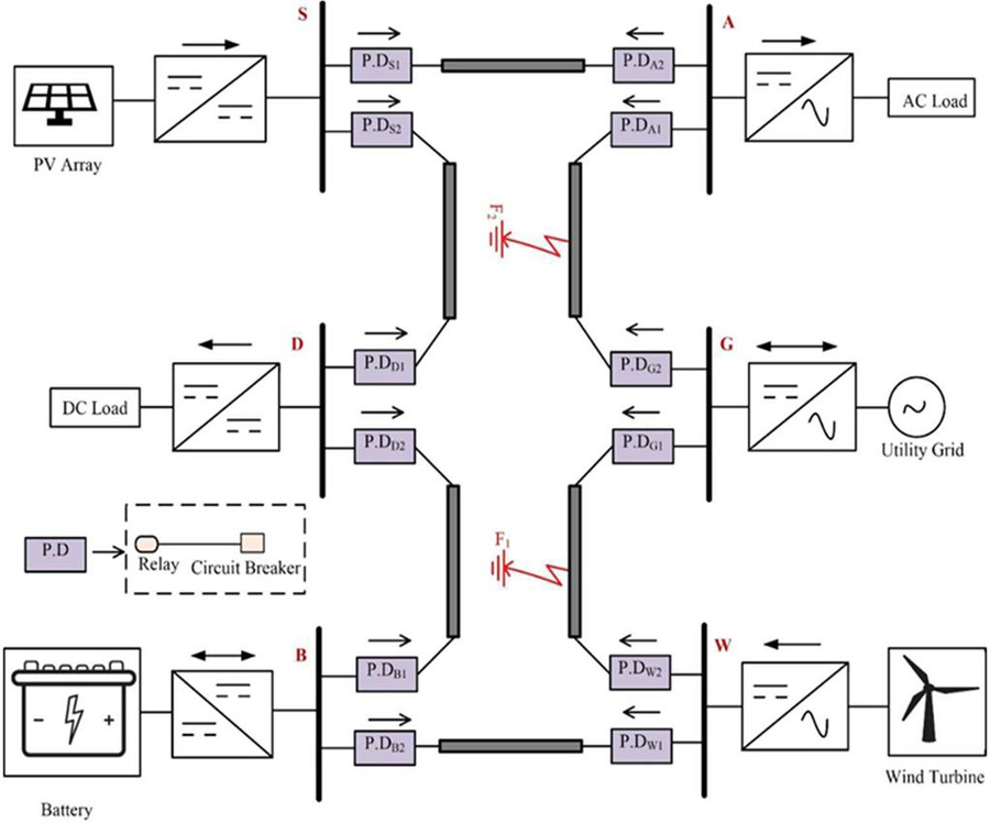
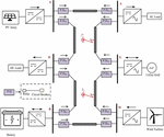
Figure 1 Architecture of six-terminal DC microgrid.
Table 1 Test system data [27]
| Parameter | Ratings |
| System voltage | 350 V |
| Base Power | 500 kW |
| Battery | 96V, 0.4kAh |
| Battery converter | 125 kW |
| Solar panel | VV, IA, P W |
| PV DC-DC converter | 125 kW |
| Wind turbine | 500 kW |
| VSC interfaced to grid | 250 kW |
| Resistance | 0.125 /km |
| Inductance | 0.97 mH/km |
| Capacitance | 12.1 mF/km |
| Constant Impedance Load | 250 kW |
| Single-phase AC load | 250 kW, 0.8 power factor lagging |
2 Proposed Protection Technique
The schematic diagram of the six terminal ring configuration DC microgrid is under test, as given in Figure 1. The system ratings of the tested microgrid are listed in Table 1. The DC microgrid constitutes solar PV, battery for storage, wind turbine, alternate current (AC) load, DC load, and AC grid. All resources and loads are interfaced to the DC grid through appropriate converters, where solar PV and wind turbine generates maximum power with the help of maximum power point tracking (MPPT) technique [25]. The battery works as a backup source for power management and controlled using a bidirectional DC-DC converter [26]. Each line segment of the network is modelled as II-network. Each line terminal is associated with a voltage sensor, current sensor, and protection device (PD) to provide an appropriate trip signal to the breakers.
2.1 Fault Line Identification and Isolation
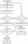
Due to the shorter length of line, low value of line resistance, and interfaced power electronic converters, the protection algorithm needs to produce a trip signal faster. This paper proposes the flow of the proposed method, as illustrated in Figure 2. To begin with, by using the local values of voltage and current, the inductance has been estimated. The non-zero inductance value corroborates that system subjected to the disturbance. Further, it is necessary to discriminate internal and external faults to enhance the selectivity of the protection system. If both the end protection devices (PDs) in a line detect a fault in the forward direction, it is confirmed as internal fault by PDs. However, for external fault, one end of the protection device (PD) senses the fault in the forward direction and the other end PD observes the same fault in the reverse direction [5, 27]. In this connection, the fault analysis has been performed by considering faults F and F in the lines GW and GA, respectively, as shown in Figure 1. For a detailed understanding, the three bus system is considered (part of tested microgrid) as depicted in Figures 3 and 4. Assume that pre-fault current is directed from bus G to W.
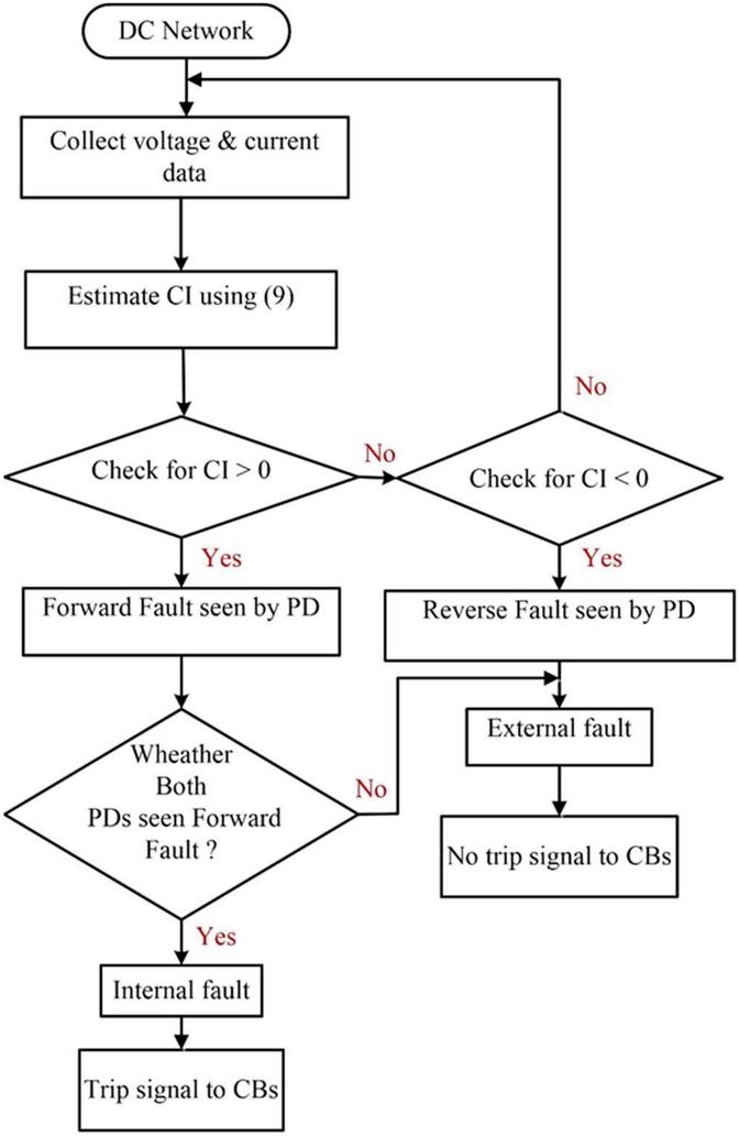
Figure 2 The flowchart of proposed protection method.
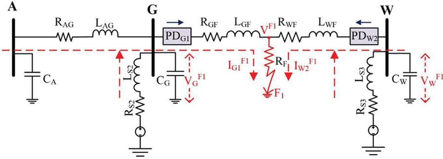
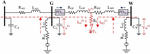
Figure 3 Model for internal fault analysis.
2.1.1 Internal fault analysis
When the system is operating under normal or steady operating conditions, the voltage at PD in the line GW is
| (1) |
V and V are pre-fault voltages measured at the PD and PD, respectively, R is the total resistance of the GW line, and I is current measured at PD.
For the pole-ground fault (F), as shown in Figure 3, the voltage at PD during transient conditions is
| (2) |
where, and are voltages sensed at PD and fault point, respectively. R and L are resistance and inductance from PDG1 to fault location (F).
Using (1) and (2)
| (3) |
where, , it represents the change in voltage observed by PD during the fault and (3) can be written in matrix as
| (4) |
Similarly, expression at PD during F is
| (5) |
where, and are the pre-fault and fault currents noted at PD, respectively, and are the pre-fault and fault voltages at bus W, respectively, R and L are resistance and inductance from PD to fault location (F).
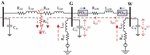
2.1.2 External fault analysis
For the ground fault (F) in the line GA as depicted in Figure 4, the voltage at PD is
| (6) |
where, is current measured at PD during F, and are the voltages measured at PD and PD, respectively. and represents the inductance and resistance of the GW line.
Using (1) and (6), the change in voltage observed at PD is
| (7) |
Similarly, the change in voltage observed at PD is
| (8) |
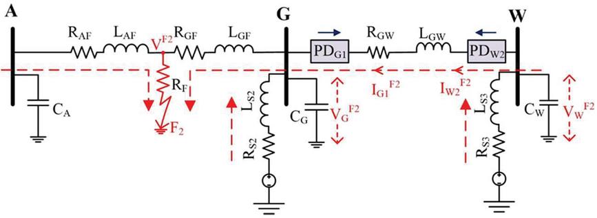
Figure 4 Model for external fault analysis.
Using the Least Square Estimation method, the expressions (4), (5), (7), and (8) would be solved. It reveals that in the case of a forward fault (F), both PD and PD carry positive inductance coefficients. But for a reverse fault (F), PD and PD have a negative and positive coefficient, respectively. The estimation of change in inductance (CI) as follows
| (9) |
Eight consecutive samples of inductance at a sampling rate of 8000 Hz have been considered to estimate change in inductance. From this information, the sign of CI is positive and negative for forward fault and reverse fault, respectively. Moreover, if both end protection devices hold positive signs, the fault is treated as an internal fault and allows the corresponding circuit breakers to operate; otherwise, the fault is external and no operating signal is issued to the breakers.
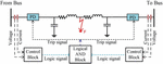
2.2 Protection Arrangement for Isolation of Faulty Line
The protection arrangement between two protection devices located on both terminals of the line plays an essential role in enhancing the selectivity and reliability of the protection system. The effective protection arrangement for the trip signal generator is illustrated in Figure 5. Appropriate isolation of faulty line enhances the continuity in power supply to the consumers to increase the reliability of the microgrid. By employing local current and voltage samples data, the polarity of change in inductance is computed using (9) immediately after fault initiation. The polarity of computed change in inductance is positive for forward fault and the control block produces logic signal ‘1’. The other way around, computed inductance holds a negative value for reverse fault and logic signal ‘0’ has been produced.
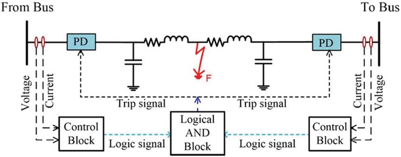
Figure 5 Protection arrangement for isolation of faulty line.
In case of the internal fault, the logic signal produced by both control blocks would be logic ‘1’, and as a result, the logical AND block will issue trip signals to breakers to isolate the faulty line. For external fault, anyone of the control blocks obtains logic ‘0’ and results in no function of circuit breakers.
3 Results and Discussions
The technique is proposed for the detection and isolation of fault for multi-terminal DC microgrid has been modelled and simulated using Matlab/Simulink tool and the response of the grid model under different fault conditions is analysed. The genuineness of the proposed protection method has been simulated and verified on a six terminal DC microgrid during dissimilar abnormal conditions.
3.1 Internal Fault Case
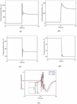
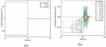
A pole-ground fault with fault resistance of 0.1 is placed in the GW line at a distance of 0.2 km from bus G at the time (t) 0.4 s, as shown in Figure 1. The three bus system has been considered for this fault study, as depicted in Figure 3. The current and voltage waveforms at PD and PD are shown in Figure 6.
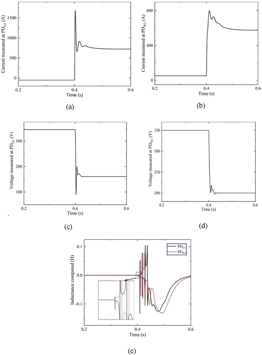
Figure 6 Current measured at (a) PD (b) PD, Voltage measured at (c) PD (d) PD, (e) Inductance computed at PD and PD.
From the results, the voltage, current values are committed with transients, and an increment in the current, decrement in voltage has been observed. As the fault is located nearer to PD, the impact of fault at PD is more as compared to PD. During the disturbance, both end protection devices compute inductance, as shown in Figure 6(e).
Subsequently, the change in inductance is calculated by employing (9) and it is seen that both PD and PD hold positive values immediately after initiation of fault. The concern relays identified the fault in the frontward direction and corroborated that the fault is internal. Consequently, the two relays associated with the fault line feed the enable signal to logic AND block, which grant trip signals to concern breakers. Hence, this protection approach effectively isolates the faulty line from the microgrid.
3.2 External Fault Case
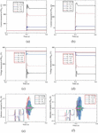
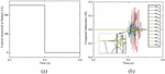
The ground fault with R is created at 0.5 km distance from bus A in AG line at time (t) 0.4 s as shown in Figure 5. During this fault case, concern PDs sense changes in the voltage and current have presented in Figure 7. This fault study reveals that, a uniform change in current at both PD and PD and these currents contains transient rise and dip. As the fault is located closer to PD, Consequently, the reduction in voltage at PD is slightly more than the voltage at PD.
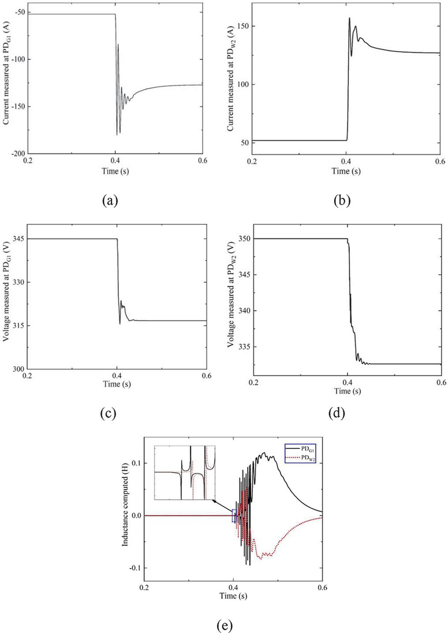
Figure 7 Current measured at (a) PD (b) PD, Voltage measured at (c) PD (d) PD, (e) Inductance computed at PD and PD.
Figure 7(e) shows the computed values of inductance at PD and PD and the change in inductance is calculated by adopting (9). It demonstrates that the computed value at PD and PD carries negative and positive values, respectively, immediately after fault initiation. It confirms as the PD is sensed the fault in the AG line as a reverse fault and the same fault treated as forward fault concerned to the PD. The concern relays identified the fault in the frontward direction and corroborated that the fault is internal. Consequently, the PD and PD produce logic ‘1’ and ‘0’, respectively. The logic AND block will not grant trip signals to concern breakers. Hence, this proposed protection approach improves the selectivity of the protection system.
3.3 Impact of Fault Resistance
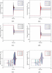
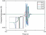
The proposed protection algorithm has been examined by considering the pole-ground fault in the WB line at 0.4 km distance from bus W and fault resistance (R) value ranging from 0 to 15 . The voltage and current waveforms as shown in Figure 8.
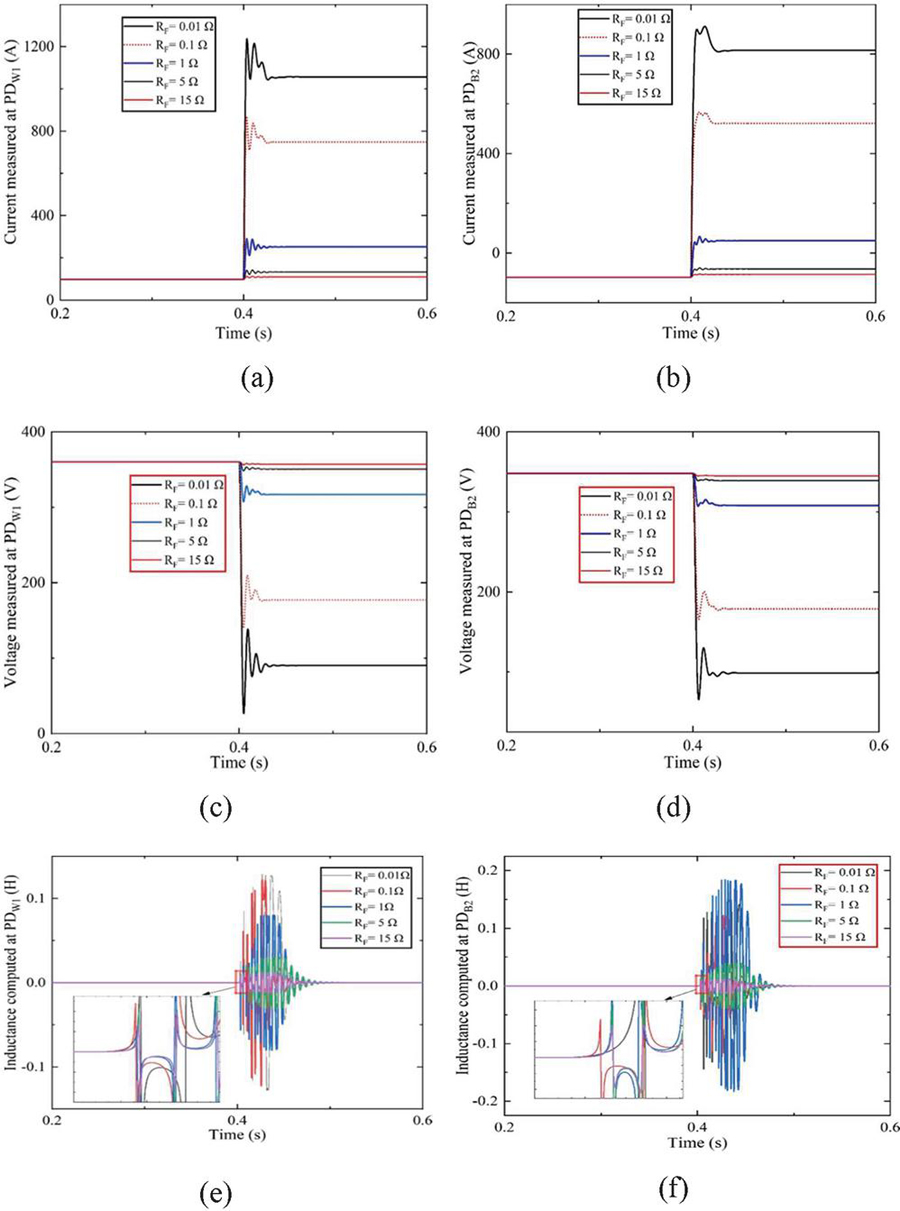
Figure 8 Current measured at (a) PD (b) PD, Voltage measured at (c) PD (d) PD, Inductance computed at (e) PD (f) PD.
From this fault investigation, when fault resistance increases, then the fault current decreases. Concurrently, the value of voltage measured at relay will increase with fault resistance. From Figure 8(e) & (f), the computed inductance at PD and PD have positive values immediately at fault inception for different fault resistance. Consequently, the corresponding protection devices confirm the fault as internal fault, and appropriate signal would be issued to operate breakers.
3.4 Impact of Fault Location
A fault in the WB line with R is simulated for various fault locations to examine the proposed algorithm. In this case, the location of the fault is represented by ‘P’ w.r.t. PD. The currents and voltages sensed at PD and PD have presented in Figure 9. When the fault location moves towards another end of the same line segment, the values of current and voltage decrease and increase, respectively, and there is a reduction in current transients. It noted that the location of the fault also affects the system performance.
Figure 9(e) & (f) shows that for all the cases, the computed value of inductance by concern PDs remains positive, and the proper operation of breakers takes place to isolate the line. Hence, the accuracy of the proposed method is not affected by the fault location, which will improve the dependability of relay.
3.5 Radial Configuration
This protection method is also simulated for the sudden removal of the line segment due to its maintenance. The DS line is disconnected at t 0.4 s from rest of the system to test the functionality of the proposed method during unhealthy conditions. The current measured values at PD and PD are presented in Figure 10.
The computed inductance at various protection devices is displayed in Figure 10(b) and by using (9) the sign of CL has been obtained. Figure 10(b) it confirms that PD, PD, PD, PD have positive inductance values and heeded the disturbance in the forward direction.
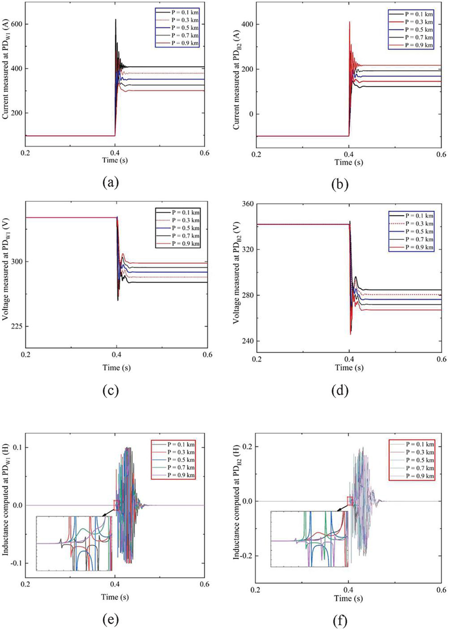
Figure 9 Current measured at (a) PD (b) PD, Voltage measured at (c) PD (d) PD, Inductance computed at (e) PD (f) PD.
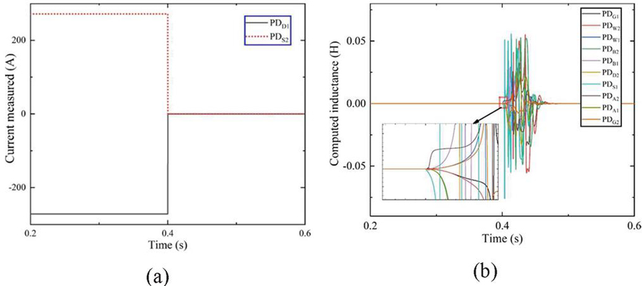
Figure 10 (a) Current measured at PD and PD (b) Inductance computed at all PDs.
However, PD, PD, PD, PD, PD, PD have negative inductance values and detect the disturbance in the reverse direction.
3.6 Effect of Source Outage
Consider the battery is out of service due to service maintenance and during such case, the current supplied by the battery source becomes zero at t 0.4 s, as shown in Figure 11. The inductance computed at all PDs is displayed during this validation process in Figure 11. Immediately after the disturbance, PD, PD, PD, PD, PD hold positive inductance values and identified the disturbance as a forward fault. However, PD, PD, PD, PD, PD, PD, PD owned the negative values of inductance and disturbance identified as a reverse fault.

Figure 11 (a) Current measured at battery terminal (b) Inductance computed at various PDs.
3.7 Sudden Change in Load
To examine the protection algorithm to enhance security, the disturbance in load is created at t 0.4 s at bus D. The simulation has been carried out for overloading conditions like 150% of its rated load.
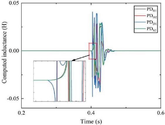
Figure 12 Inductance computed during sudden load change.
Under these conditions, the computed inductance values at PD and PD carry a positive identity. Simultaneously, PD and PD have a negative identity, as shown in Figure 12. Hence the proposed algorithm will not respond to the sudden change in the load, strengthening the security of the protection system.
4 Conclusion
The protection of ring configuration DC microgrid plays a crucial role in the distributed system because of the current limiting nature of converters and bi-directional power flow. This research proposes an accurate and reliable protection scheme for a ring configured DC microgrid that includes detection of disturbances like fault and sudden load changes. This method also identifies and isolates the faulty line for reliable operation. In the proposed method, the sign of CI is used to categorize internal and external faults with accurate communication between PDs on both ends. The proposed protection scheme has been tested on a 6-Bus ring configured DC microgrid in MATLAB/Simulink tool for several dissimilar abnormal conditions such as low and high resistance magnitude faults, the impact of fault location in a line segment, sudden removal of the line, inactive operation of solar PV due to natural variation in solar irradiation and sudden switching operation of loads. From the fault study, it is noted that the proposed protection algorithm has improved the selectivity, dependability, security and reliability. This method is found to be fast and accurate during the aforementioned cases as a consequence the detriment of power electronic switches can be prevented.
References
[1] D. Salomonsson, L. Söder, and A. Sannino, “Protection of low-voltage DC microgrids,” IEEE Trans. Power Deliv., vol. 24, no. 3, pp. 1045–1053, 2009, doi: 10.1109/TPWRD.2009.2016622.
[2] H. J. Laaksonen, “Protection principles for future microgrids,” IEEE Trans. Power Electron., vol. 25, no. 12, pp. 2910–2918, 2010, doi: 10.1109/TPEL.2010.2066990.
[3] E. Sortomme, S. S. Venkata, and J. Mitra, “Microgrid protection using communication-assisted digital relays,” IEEE Trans. Power Deliv., vol. 25, no. 4, pp. 2789–2796, 2010, doi: 10.1109/TPWRD.2009.2035810.
[4] R. Mohanty, S. Sahoo, A. K. Pradhan, and F. Blaabjerg, “A cosine similarity-based centralized protection scheme for dc microgrids,” IEEE J. Emerg. Sel. Top. Power Electron., vol. 9, no. 5, pp. 5646–5656, 2021, doi: 10.1109/JESTPE.2021.3060587.
[5] G. K. Rao and P. Jena, “Fault Detection in DC Microgrid Based on the Resistance Estimation,” IEEE Syst. J., pp. 1–12, 2021, doi: 10.1109/JSYST.2020.3046054.
[6] S. D. A. Fletcher, P. J. Norman, S. J. Galloway, P. Crolla, and G. M. Burt, “Optimizing the roles of unit and non-unit protection methods within DC microgrids,” IEEE Trans. Smart Grid, vol. 3, no. 4, pp. 2079–2087, 2012, doi: 10.1109/TSG.2012.2198499.
[7] T. S. Ustun, C. Ozansoy, and A. Zayegh, “Fault current coefficient and time delay assignment for microgrid protection system with central protection unit,” IEEE Trans. Power Syst., vol. 28, no. 2, pp. 598–606, 2013, doi: 10.1109/TPWRS.2012.2214489.
[8] G. Allee and W. Tschudi, “Edison redux: 380 Vdc brings reliability and efficiency to sustainable data centers,” IEEE Power Energy Mag., vol. 10, no. 6, pp. 50–59, 2012, doi: 10.1109/MPE.2012.2212607.
[9] A. Pratt, P. Kumar, and T. V. Aldridge, “Evaluation of 400V DC distribution in telco and data centers to improve energy efficiency,” INTELEC, Int. Telecommun. Energy Conf., pp. 32–39, 2007, doi: 10.1109/INTLEC.2007.4448733.
[10] R. Uluski et al., “Microgrid controller design, implementation, and deployment: A journey from conception to implementation at the Philadelphia Navy Yard,” IEEE Power Energy Mag., vol. 15, no. 4, pp. 50–62, 2017, doi: 10.1109/MPE.2017.2691239.
[11] L. Tang and B. T. Ooi, “Locating and isolating DC faults in multi-terminal DC systems,” IEEE Trans. Power Deliv., vol. 22, no. 3, pp. 1877–1884, 2007, doi: 10.1109/TPWRD.2007.899276.
[12] A. Meghwani, S. C. Srivastava, and S. Chakrabarti, “A Non-unit Protection Scheme for DC Microgrid Based on Local Measurements,” IEEE Trans. Power Deliv., vol. 32, no. 1, pp. 172–181, 2017, doi: 10.1109/TPWRD.2016.2555844.
[13] S. Dhar and P. K. Dash, “Differential current-based fault protection with adaptive threshold for multiple PV-based DC microgrid,” IET Renew. Power Gener., vol. 11, no. 6, pp. 778–790, 2017, doi: 10.1049/iet-rpg.2016.0577.
[14] P. Cairoli and R. A. Dougal, “Fault detection and isolation in medium-voltage DC microgrids: Coordination between supply power converters and bus contactors,” IEEE Trans. Power Electron., vol. 33, no. 5, pp. 4535–4546, 2018, doi: 10.1109/TPEL.2017.2724145.
[15] S. Azizi, M. Sanaye-Pasand, M. Abedini, and A. Hassani, “A traveling-wave-based methodology for wide-area fault location in multiterminal DC systems,” IEEE Trans. Power Deliv., vol. 29, no. 6, pp. 2552–2560, 2014, doi: 10.1109/TPWRD.2014.2323356.
[16] K. Saleh, A. Hooshyar, and E. F. El-Saadany, “Fault detection and location in mediumvoltage DC microgrids using travelling-wave reflections,” IET Renew. Power Gener., vol. 14, no. 4, pp. 571–579, 2020, doi: 10.1049/iet-rpg.2019.0370.
[17] L. Kong and H. Nian, “Fault Detection and Location Method for Mesh-Type DC Microgrid Using Pearson Correlation Coefficient,” IEEE Trans. Power Deliv., vol. 36, no. 3, pp. 1428–1439, 2021, doi: 10.1109/TPWRD.2020.3008924.
[18] N. Bayati, H. R. Baghaee, A. Hajizadeh, and M. Soltani, “Localized protection of radial DC microgrids with high penetration of constant power loads,” IEEE Syst. J., vol. 15, no. 3, pp. 4145–4156, 2020, doi: 10.1109/JSYST.2020.2998059.
[19] J. Do Park, J. Candelaria, L. Ma, and K. Dunn, “DC ring-bus microgrid fault protection and identification of fault location,” IEEE Trans. Power Deliv., vol. 28, no. 4, pp. 2574–2584, 2013, doi: 10.1109/TPWRD.2013.2267750.
[20] D. K. J. S. Jayamaha, N. W. A. Lidula, and A. D. Rajapakse, “Wavelet-Multi Resolution Analysis Based ANN Architecture for Fault Detection and Localization in DC Microgrids,” IEEE Access, vol. 7, pp. 145371–145384, 2019, doi: 10.1109/ACCESS.2019.2945397.
[21] W. Xiang, S. Yang, L. Xu, J. Zhang, W. Lin, and J. Wen, “A Transient Voltage-Based DC Fault Line Protection Scheme for MMC-Based DC Grid Embedding DC Breakers,” IEEE Trans. Power Deliv., vol. 34, no. 1, pp. 334–345, 2019, doi: 10.1109/TPWRD.2018.2874817.
[22] R. Mohanty and A. K. Pradhan, “Protection of smart DC microgrid with ring configuration using parameter estimation approach,” IEEE Trans. Smart Grid, vol. 9, no. 6, pp. 6328–6337, 2018, doi: 10.1109/TSG.2017.2708743.
[23] N. Yadav and N. R. Tummuru, “A Real-Time Resistance Based Fault Detection Technique for Zonal Type Low-Voltage DC Microgrid Applications,” IEEE Trans. Ind. Appl., vol. 56, no. 6, pp. 6815–6824, 2020, doi: 10.1109/TIA.2020.3017564.
[24] V. Nougain and B. K. Panigrahi, “Detection of DC System Faults Based on the Principle of Threshold Violation in i-r Plane,” IEEE Syst. J., vol. 15, no. 1, pp. 856–864, 2021, doi: 10.1109/JSYST.2020.3010370.
[25] S. S. Gite and S. H. Pawar, “Modeling of wind energy system with MPPT control for DC microgrid,” Proc. 2017 2nd IEEE Int. Conf. Electr. Comput. Commun. Technol. ICECCT 2017, 2017, doi: 10.1109/ICECCT.2017.8118026.
[26] Z. Yi, W. Dong, and A. H. Etemadi, “A unified control and power management scheme for PV-Battery-based hybrid microgrids for both grid-connected and islanded modes,” IEEE Trans. Smart Grid, vol. 9, no. 6, pp. 5975–5985, 2018, doi: 10.1109/TSG.2017.2700332.
[27] R. Mohanty and A. K. Pradhan, “DC ring bus microgrid protection using the oscillation frequency and transient power,” IEEE Syst. J., vol. 13, no. 1, pp. 875–884, 2019, doi: 10.1109/JSYST.2018.2837748.
Biographies

N. Nageswara Reddy received the B.tech. degree in Electrical and Electronics Engineering from JNTU, India, in 2008 and the M.Tech. degree in power systems engineering from the National Institute of Technology Calicut, India, in 2011. He is currently working toward the Ph.D. degree in Electrical Engineering with the National Institute of Technology Tiruchirappalli, Tiruchirappalli, India. His research interests include renewable energy integration, protection and control of microgrids and FACTS controller.

Rajesh Velpula received the B.tech. degree in Electrical and Electronics Engineering from Acharya Nagarjuna University, India, in 2008, and the M.Tech. degree in power systems engineering from JNTUK, India, in 2010. I am currently working towards the Ph.D. degree in Electrical Engineering with the National Institute of Technology Tiruchirappalli, Tiruchirappalli, India. My research interests include power system protection, microgrids.

P. Raja received the B.E. degree in electrical and electronics engineering from Manonmaniam Sundaranar University, Tirunelveli, India, in 2000, the M.Tech. degree in energy systems from IIT Madras, Madras, India, in 2001, and the Ph.D. degree from the National Institute of Technology, Tiruchirappalli, India, in 2013. He has 15 years of teaching and research experience in the field of power systems. He is currently an Associate Professor in the Electrical and Electronics Engineering Department, NIT Tiruchirappalli, Tiruchirappalli, India and is associated with the Hybrid Electrical Systems Laboratory. His areas of interest include renewable energy systems, electrical machines, and power system protection, microgrid protection.

S. Moorthi received the B.E. degree in electrical and electronics engineering from the University of Madras, Chennai, India, in 2001, the M.E. degree in applied electronics from the PSG College of Technology, Coimbatore, India, in 2003, and the Ph.D. degree in the area of very large scale integration (VLSI) for communication circuits from Anna University, Chennai, India, in 2008. He was a Postdoctoral Fellow of the Erasmus Mundus External Cooperation Window initiated under the EURINDIA Program, through which he has done postdoctoral research on memory design for reconfigurable architectures with the Royal Institute of Technology (KTH), Stockholm, Sweden, in 2010–2011. Since 2007, he has been a member of faculty of the Department of Electrical and Electronics Engineering, National Institute of Technology Tiruchirappalli, Tiruchirappalli, India, where he is also associated with the Hybrid Electrical Systems Laboratory. His research interests include VLSI for Digital Controllers for Power Applications, signal processing and embedded systems.
Distributed Generation & Alternative Energy Journal, Vol. 38_2, 691–714.
doi: 10.13052/dgaej2156-3306.38214
© 2023 River Publishers