Design and Analysis of Solid State DC-AC Transformer
K. Suresh1,*, I. Kumaraswamy1 and R. Arulmozhiyal2
1Department of EEE, Sree Vidyanikethan Engineering College, Tirupati, India
2Department of EEE, Sona College of Technology, Salem, India
E-mail: sureshk340@gmail.com
*Corresponding Author
Received 09 October 2021; Accepted 19 December 2021; Publication 27 February 2023
Abstract
Multimodal single/dual stage conversion (BSDC) based on a new solid-state DC-AC transformer (SDAT) is proposed. The suggested conversion can perform variable or constant DC voltage operation. A variable DC voltage is controlled dynamically in response to changes in DC input side voltage, allowing the DC-DC conversion stage to always operate at its best. New DC-AC power conversion of 2 port two-way choppers (TBDC) and two-way rectifier/inverter conversion (BRIC) was planned for the implementation of the proposed SDAT. SDAT, consisting of a bi-directional step-down-step-up converter and a bi-directional step-up-step-down converter, has been used as a prototype model to check the suggestion system. Functional concepts of this BSDC converter with TBDC are designed and simulated on the MATLAB/simulink environment network. PWM and control methods have been applied for SDAT to accomplish a wide variety of voltage and power loss reduction in the proposed device. Test bench model hardware is designed and tested to validate the effectiveness and benefits of the proposed approach.
Keywords: Multimodal single/dual stage conversion, solid-state DC-AC transformer, Two port two-way choppers, Pulse width modulation, DC-AC conversion.
1 Introduction
Rapid growth of renewable energy resources, smart grids, modern electric vehicles, high power and energy system has crucial in shaping the stable and reliable activity of such conversion system [1, 2]. Multimodal inverter is the main device used to integrate with utility grid and the energy storage unit, including the batteries or ultra-capacitor, capable of handle the dynamic and multi flow of power and to start charging the storage element [3]. The voltage level of batteries varies greatly depending on the stage of charge. Big problem during designing and installation of high behaviour multimodal inverter will be how to obtain higher power transfer and flexible voltage control [4, 5]. Dielectric insulation is typically available for charging and discharging electric cars and low voltage battery storage systems [6]. For multimodal core-type DC-AC power transfer, 2 stages expand the existing of an core-type Multimodal chopper converter and a regular multimodal DC-AC/AC-DC converter is commonly used in electrical system which is illustrated in Figures 1 and 2 illustrated proposed system of energy conversion.
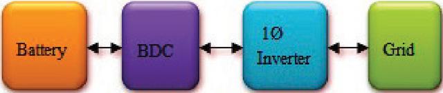
Figure 1 Existing cascaded system.
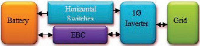
Figure 2 Proposed system of energy conversion.
The multimodal Chopper regulates the battery’s charge/discharge and ensures a consistent V on the DC [7, 8]. The multimodal inverter governs grid current and connects the DC bus to the Main grid.
In this situation, the multimodal Chopper assumes full responsibility for the battery’s broad voltage control [9, 10]. An independent multimodal converter is much more complex and expensive to deploy than unidirectional discrete PWM and evocative chopper [11, 12]. TBDC converter is appealing solution among numerous multimodal chopper converters owing to its improved smooth switching efficiency and power control capacity [13, 14]. Even then, the multimodal TBDC converter performs better when the switching frequency is set to the resonant frequency of all its tank circuit. When the voltage of the TBDC converter ranges widely, it is hard to achieve performance across the whole operating range [15, 16]. While several new topologies, control techniques, and design techniques for multimodal choppers were proposed, high performance is still tough to accomplish when a unidirectional voltage is controlled over a wide range [17]. Furthermore, since the gain of the voltage of normal and reversal mode of TBDC vary, it’s indeed difficult to obtain a quick and fast response when the converter energy flowing path is shifted. Multiple input inverters with an active DC voltage were suggested to address these disadvantages. The primary aim of this approach is to run the chopper with SDAT in order to maximize performance and optimize regulation of the multimodal chopper. Unidirectional voltage output, on the other hand, must be adjusted in response to changes in the battery voltage, resulting in a variable DC voltage [18]. The highest DC voltage would be more than the traditional two conversion systems of constant DC voltage [19, 20]. Since the minimum DC voltage must be higher than the peak amplitude of AC voltage to ensure proper operation of the multimodal inverter. As just a consequence, even higher voltage control devices and DC capacitors must be used, resulting in higher switching losses. Smooth switching methods were used to eliminate switching errors in the multimodal inverter. Soft-switching techniques were employed for the multimodal inverter to reduce switching losses. A significant disadvantage of the smooth inverter, in contrast to the dynamic power, is the additional load ripple and low resistance. Because of reduced power conversion stage, a single-stage multimodal Inverter seems appealing. Packet switched T-source or quasi Z-source inverters are appealing for normal implementations. Even so, designing a single-stage multimodal Inverter for discrete approaches to improve effective AC current control and DC voltage/current control over a large variety is far more complicated. Circuit diagram of the proposed model is as shown in Figure 3. The main purpose of this work is to suggest a new a double 2 stage design for multimodal independent DC-AC power transfer, as well as a voltage regulation technique. Revised version of core-type multimodal chopper and BRIC circuit groups is also planned. To investigate the structure of the selected approaches, one of the suggested two input Inverters composed of a TBDC converter and a T-type BRIC is used as an illustration. The following is a breakdown of the paper’s structure. For two input independent DC-AC power conversion, a new configuration and groups of multimodal 3 port DC-DC and DC-AC control schemes are suggested in Section 1. Section 2 discusses the operation rules, power, modulation techniques, and features of one of the suggested multimodal Inverters. The findings of the experiments are presented in Section 4. Finally, in Section 5, conclusions would be drawn.

Figure 3 Proposed converter (SSD).
2 DC-AC Power Conversion
2.1 Proposed System
Figure 1 shows the configuration of a 2 stages multimodal integrated inverter, which consists of a multimodal core-type DC conversion stage and a quasi-DC-AC level. The voltage gain of the multimodal DC-DC level must be hung as per the difference of the battery to achieve a steady Bus voltage. As is well known, achieving a high performance multimodal independent Chopper with a broad voltage range is nearly impossible. High enhanced performance for all active power directions can be easily accomplished if the voltage gain of a multimodal Chopper is still unchanged. For e.g., if the frequency range of a multimodal TBDC conversion is often the same as frequency response of its tank circuit, high quality can be obtained. Even then, unless the step-up of the DC-DC level remains constant, a dynamic battery voltage will result in a varying DC voltage, which would be inappropriate for the DC-AC level in the conventional 2 stages configuration seen in Figure 1. To address this problem, a new a double carriage approach is developed for two input Power electronic transition. The DC throughout the traditional 2 stages configuration is separated into two DC, as seen in Figure 3. V is a DC with a fixed voltage, equivalent to the DC in a traditional 2 stages layout. V is yet another DC which voltage varies in accordance with the voltage supply. And then when the voltage level ranges widely, a consistent voltage gain for the multimodal chopper level can be obtained by adjusting the voltage of V. As a consequence, the multimodal chopper waveform operating state can be streamlined, the chopper architecture and execution can be reduced, and high performance can be obtained.
2.2 Solid State DC-AC Transformer
The suggested technique focuses on three multimodal Power converter and 3 port multimodal DC-AC/AC-DC that can communicate with dc Power at the same time.
2.2.1 DC conversion stages (Single stage AC-DC conversion)
On the basis of a traditional 2 port power converters, a two multimodal Chopper can indeed be developed. As either an instance, know the entire multimodal TBDC conversion. To receive two Variable dc interfaces, the supplementary side huge rectifier could be broken into two independent shifting legs with a commonality and greater intended interfaces. Single stage AC-DC conversion is illustrated in Figure 4.
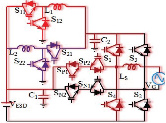
Figure 4 Single stage AC-DC converter.
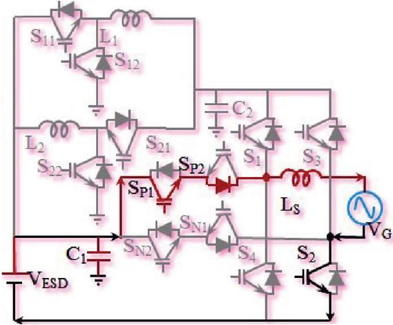
Figure 5 Single stage DC-AC converter.
2.2.2 Single stage inversion
To integrate multiple output sources of energy, multiple input Power electronic converters are being suggested, and comprehensive computational complexity de-fuzzification systems have been suggested in that include a strong guide for designing BRIC optimization techniques. A traditional full-bridge multimodal step-up converter is made up of two multimodal Step-down staircases. A traditional Step-down converter only has one Input dc port, but using the mentioned methods in it can be converted to a multi-input Step-down – step-up converter. Figure 5 depicts the single stage inversion.
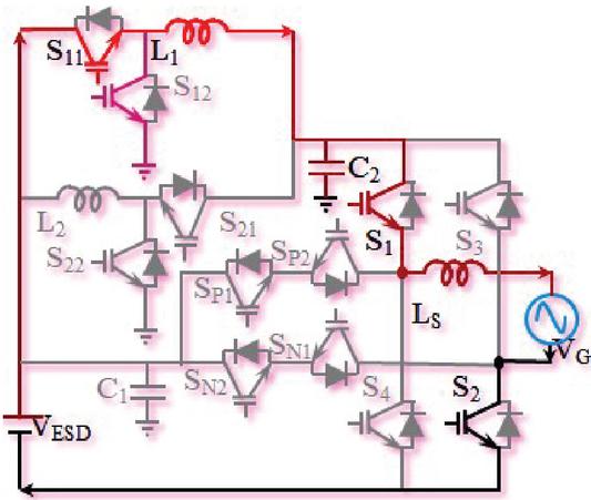
Figure 6 Double stage boost DC-AC converter.
2.2.3 Double stage inversion
Figure 6 shows a new 2 stages multimodal DC-AC conversion made up of the 3 port TBDC conversion and current path is shown in red colour line, pink colour lines indicated freewheeling path.
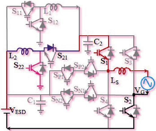
Figure 7 Double stage Buck DC-AC converter.
Figure 7 shows a new 2 stages multimodal AC-DC conversion made up of the 3 port TBDC conversion, blue colour lines indicated charging current path and main current path is shown in red colour line. This converter can perform AC-DC and DC-AC operations with boost and buck in opposite direction as compared to Figures 6 and 7.
2.2.4 Proposed converter analysis
The following equation is solved by the volt-second equilibrium of the inductors:
| (1) |
Where, V and V are the DC voltages.
C2 DC bias voltage is (V–V)/2 that is not the case for a traditional TBDC converter. The current of the addition of energy is spherical in the both half cycles, as seen in Figure 10. As a result, the DC typical currents V and V satisfy the following equation:
| (2) |
Where I, I and I are the average current of battery
| (3) | |
| (4) |
TRIC duty cycles are calculated and given as LOW voltage port
| (5) |
Two port
| (6) |
High voltage port
| (7) |
The power ratio and the transfer voltage have a relationship.
| (8) | |
| (9) | |
| (10) |
3 Control Strategy
Overall control strategy is as shown in Figure 8. The typical multimodal Inverter control system flow chart. For the BSDC, a current feedback controller is used, with the relation I of the required to charge current determined by the condition of the device. To reduce a double paragraph wave, the BSDC can adjust its duty cycle significantly. The BRIC controls the AC current I as well as the voltages V and V. The voltage comparisons of V and V must meet the following conditions, as per the review in Section 3:
| (11) |
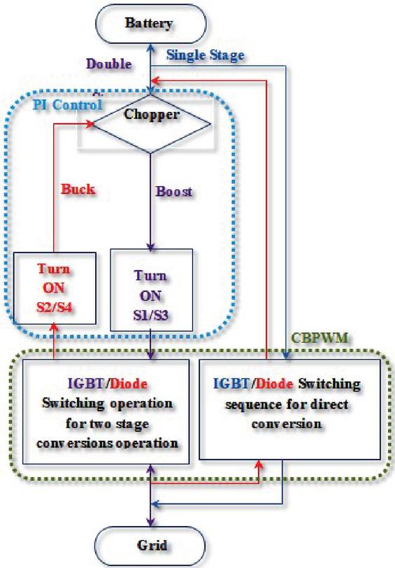
Figure 8 Control strategy.
As the voltage level V increases V remains unchanged whereas V changes. The BRIC uses a control mechanism close to that of a traditional multimodal Inverter. V is controlled by a voltage regulator, whose performance defines the AC grid current reference maximum values I. The duty cycle of S2 and S1 in different operation mode can be expressed by:
| (12) |
The AC voltage should be called stable before and after mode switching since the switching frequency is much greater than the frequency of the AC voltage. The relationship between vcl, V, and V can be deduced from (5), (6), (7), and (12). Furthermore, since S1 overall service period is 1, vc1 highest values should be reduced to one. Likewise, since S1 minimum service period is zero, V minimum value must be set to one. As a result, in the both half cycles of utility grid, V and V are expressed as:
| (13) |
The mode transformation among V level1 and level2 could be done seamlessly with a dual dependent approach, as shown in Figure 19. However, by alternating here between level2 and the V level1, the service period of S1 will shift abruptly, and the frequency powered switch can switch between S2 and S1 whenever the BRIC switches here between V-level1 and the V-level1. Maybe if one amplified wave V is being used, achieving a seamless transition between both the level2 and the V-level1, or the V-Level1 and the V-level1, is difficult. Smooth switching between these modes is accomplished by producing its other two modulated waves, V and V, and choosing the related modulated wave in separate operating modes. Furthermore, the suggested modulation strategy differs from the traditional one in that it employs various modulated waves in different operating modes.
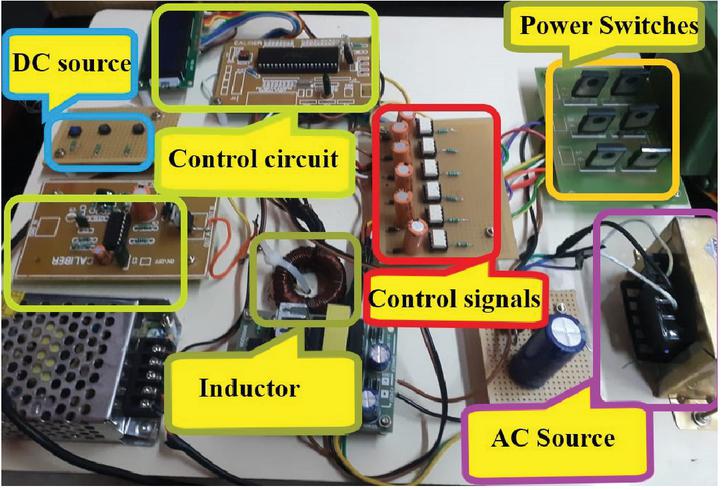
Figure 9 Experimental setup.
4 Experimental Verification
Prototype model of solid state transformer is as shown in Figure 9. For real time model investigation of the empirical knowledge, a Multimodal inverter with 3 level converters with 2 DC line is installed. Figure 11 depicts the configuration. A digital signal processor is used to apply intensity modulation and adaptive control. To meet the requirements of the away Inverter, the battery voltage V is upto 24 V, the AC signal V V AC, 50 Hz and V is planned to be 48 V DC. The frequency range of BRIC is 15 kHz, while the frequency response of BSDC is 50 kHz.
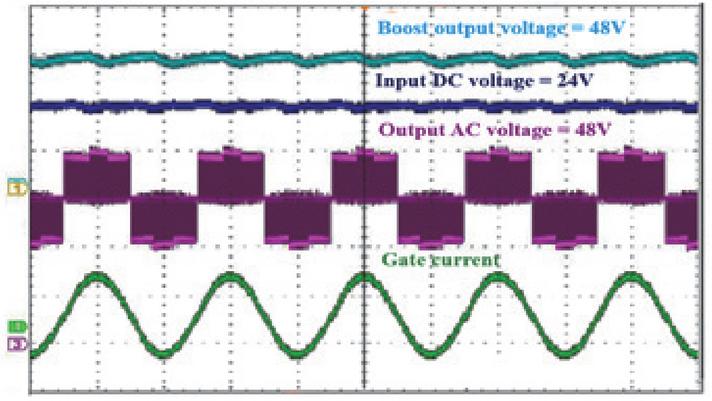
Figure 10 Boost DC-AC mode.

Figure 11 Buck DC-AC mode.
The voltages of DC lines are V and V, V is the middle point voltage, and I is the V current. The voltage of V is 24 V in Figure 10, and the BRIC operates in the V-level1, level2, and V-level1. The Electric signal I is well controlled with the proposed modulation and control technique, as can be seen. To limit switching errors, five voltage levels are collected from the middle point of the various control legs. The V voltage is 24 V, and the BRIC only operates in V-Level1 and V-level1.
Table 1 Components and parameters comparison
| Conversion Stage | Parameters | TPC-BESS [3] | PE-BSS [5] | IBP-BESS [6] | DP-BESS [7] | CHB-BESS [10] | Proposed Converter |
| DC-DC | Type | CLLC | PE | IBP | CHB | BHC | |
| Bidirectional Boost | Not possible | Not possible | Not possible | Not possible | Not possible | possible | |
| Bidirectional Boost | Not possible | Not possible | Not possible | Not possible | Not possible | possible | |
| Voltage input | V | V | V | V or V | V | V or V | |
| Voltage output | V | V | V | V or V | V | V or V | |
| AV Range | Broad | Broad | constant | Broad | Constant | constant | |
| FS Range | Broad | Broad | Narrow | Broad | Narrow | Narrow | |
| Number of switches | 2 | 2 | 2 | 2 | 2 | 4 | |
| Number of Inductors | 1 | 1 | 1 | 1 | 1 | 2 | |
| Number of capacitors | 1 | 2 | 2 | 2 | 2 | 2 | |
| Efficiency | 95.3 | 97.7 | 97.1 | 95.2 | 96.1 | 97.9 | |
| DC-AC | Type | Full bridge | Full bridge | Full bridge | Full bridge | Full bridge | DPSC |
| Number of switches | 4 | 4 | 4 | 4 | 4 | 8 | |
| Modulation technique | SPWM | Intelligent | ASPWM | SPWM | SPWM | CBPWM | |
| Cost | Less | Less | High | Less | High | High | |
| Complexity | Simple | Complex | Simple | Simple | Complex | Simple |
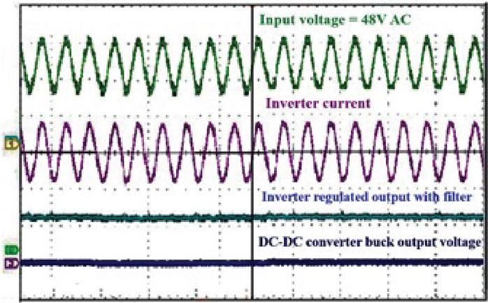
Figure 12 Buck AC-DC mode.
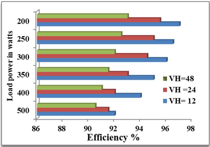
Figure 13 Efficiency versus Power.
The drive signals are, of course identical to those used in DC-AC mode. The orientation of the AC grid voltage seems to be the only distinction. During begin the voltage or current control is understood as seen in Figure 11. The waveforms of the DC-AC mode and AC-DC mode transformation are seen in Figure 12, while two DC voltages remain stable while the Grid side current overturns. Comparisons table are shown in Table 1.
Owing to the Chopper balanced normal operation and the Inverter inter characteristic, good conversion quality is obtained. These preliminary findings back up the feasibility of the proper approach. Ac power under various V is applied in all modes of operation and efficiency is calculated plotted in a graph which is as shown in Figure 13.
5 Conclusion
For independent multimodal DC-AC power converters, a modern energy conversion system is examined. A traditional 2 stages Inverter’s fixed dc line voltage is broken into a constant voltage dc line and an adjustable voltage dc line. The voltage of the dc voltage varies in response to changes in the multimodal Inverter side voltage. As a consequence, the chopper in the 2 stage system will still run at its most effective configuration. For the proposed hybrid layout, BRIC topologies were introduced. As an illustration, one of previously proposed inverters has also been thoroughly examined. The BRIC regulates the voltage of two DC bus using the suggested modulation, feature ensures, and an adaptive control approach achieves smooth behavioral intention. The suggested converter configuration, function, modulation, and control have all been thoroughly examined. The viability and efficacy of the suggested Inverter were confirmed by research observations from a model. The suggested solution tends to be high performance multimodal independent DC-AC power conversion based on analytical and empirical results.
References
[1] Murali Muniraj and R. Arulmozhiyal, “Investigation on Solar PV generation and design of switched reluctance motor for Smart Agriculture actuation system.”, Brazilian Archives Of Biology And Technology, Vol. 61: e18160767, 2018, 1–16, Sept. 2018.
[2] Arulprakash Arulmozhiyal and M. Murali, Anfis controlled solar power generation system for domestic applications, Ecology, Environment and Conversation, Vol. 23, Sept. Suppl. Issue 2017; (235–241), 2017.
[3] M. Murali & Arulmozhiyal, Intelligent Optimum Control of Brushless DC Motor, International Journal of Control Theory Applications, Vol. 10, No. 8. 49–58, March 2017.
[4] Murali Muniraj and R. Arulmozhiyal, “An improved self-tuning control mechanism for BLDC motor using Grey Wolf optimization Algorithm”, Lecturer Notes Series In Electrical Engineering Vol. 637, 315–324, Mar 2020.
[5] Murali Muniraj and R. Arulmozhiyal, “Investigation on Block Chain Based Controller Design for Bidirectional Inverter for Micro Grid Tie System”, Journal of Computational and Theoretical Nanoscience, Vol. 16, 1552–1559, APR-2019.
[6] Pothuraju, P, Subbarao, M and Suresh, K, “HBC based three phase system for wide range power conversion, ‘IEEE Canadian journal of electrical engineering., vol. 44, no. 3, pp. 321–328, Jan. 2021.
[7] Parimalasundar E and Suresh, K, “An Efficient Asymmetric Direct Current (DC) Source Configured Switched Capacitor Multi-level Inverter’, Journal européen des systèmes automatisés, Vol. 53–6, pp. 853–859. Dec. 2020.
[8] Thurairaaj, V B, Suresh, K, Srinivasa Rao, G, “Applying Three Port Converter with Dual Battery Storage System for Hybrid”, ‘Journal of scientific and industrial research, Vol. 79, pp. 640–649, July 2020.
[9] Saravana Ram, R, Lordwin cecil Prabhaker, M, Suresh, K, Kamalraj, S and Venkatesan, M, “Dynamic partial reconfiguration enhanced with security system for reduced area and low power consumption”, ‘Microprocessors and Microsystems – Elsevier, Volume 76, July 2020.
[10] Prabhu Sundaramoorthy, Balaji M, Suresh K., Ezhilventhan Natesan and Mohan K.,’Prototype implementation for vibration analysis in circuit coupled E-Core flux reversal Free stator switched reluctance motor drives,‘Circuit world, e-ISSN: Vol. 46 No. 4, pp. 325–334, April 2020.
[11] Venkatesan, M, Adhavan, B, Suresh, K, Balachander, K, and Lordwin Cenil Prabakar, M, “Research on FPGA Controlled Three Phase PV Inverter using Multi Carrier PWM Control Schemes”, ‘Microprocessors and Microsystems – Elsevier, Volume 76, July 2020.
[12] Raghavaih, K Srinivasarao G and Suresh, K, “Investigation on intelligent controllers performance used in electric vehicle application”, ‘International journal of ambient energy’ Taylor and francis, doi.org/10.1080/01430750.2020.1861092.
[13] V. B. Thurai Raaj and K. Suresh, “An Intelligent Controller based Power Grid Interconnected System for Reliable Operation,” 2019 3rd International Conference on Computing Methodologies and Communication (ICCMC), 2019, pp. 608–613, doi: 10.1109/ICCMC.2019.8819771.
[14] K. Suresh, K. Jyotheeswara Reddy, R. Dash, S. Hampannavar, R. Srikakulapu and V. Subburaj, “A Universal Converter For Different Power Conversion Operations and High Power Applications,” 2021 IEEE 12th Energy Conversion Congress & Exposition – Asia (ECCE-Asia), 2021, pp. 1666–1671, doi: 10.1109/ECCE-Asia49820.2021.9479284.
[15] Pothuraju, P Subbarao M and Suresh, K,‘Design and Analysis of Grid Tied Renewable Energy System based e-chopper Using Main Controller’, Journal européen des systèmes automatisés, Vol. 52–6, pp. 225–237, Sep 2020.
[16] Vijay babu, AR, Suresh, K and Srinivasa Rao G,‘Wind energy storage system by SOC balancing control for a stand-alone windmill’, Majlesi journal of electrical engineering, Volume 13, No. 2, pp. 7–13, June 2019.
[17] Suresh, K and Vijaybabu, AR, ‘Design and analysis of an intelligent controller for wind-solar hybrid energy conversion system’, Journal européen des systèmes automatisés, Vol. 4-62018, pp. 225–237, Dec 2018.
[18] Thurairaaj, VB Suresh, K and Arulmozhiyal R,‘BDC-Based Wind Energy Storage for Multimode Operating System’ Modelling, Measurement and control A, International Journal, ISSN: 1259-5985, Volume 91. Issue: 3, pp. 131–138, Sep 2018.
[19] Narasimha Rao Ch, N. Suresh, K. Srinivasa Rao, Y. Durga Sukumar, G. 2018, ‘Analysis of brushless direct current motor drive system for low power applications’, Journal of Advanced Research in Dynamical and Control Systems, pp. 1995–2004, Dec 2018.
Biographies

Suresh Krishnan received the Bachelor of engineering degree in electrical and electronics engineering from Government College of engineering Bargur, in 2008, Master of engineering degree in power electronics and drives from sona college of technology, in 2012 and the PhD degree in Power electronics from Anna University Chennai India, in 2017. He is currently an associate professor in the Department of electrical and electronics engineering from Sree Vidyanikethan engineering college, Tirupati, India. His research interest focuses on universal converter & controllers, hybrid electrical vehicles and DC-AC converter.

I. Kumaraswamy received the Bachelor of engineering degree in electrical and electronics engineering from Narayana engineering college, Nellore Andhra Pradesh in 2006, Master of engineering degree in power system from Sree Vidyanikethan engineering college, Tirupati, Andhra Pradesh in 2008 and the PhD degree in Power system from JNTUH in 2018. He is currently an associate professor in the Department of electrical and electronics engineering from Sree Vidyanikethan engineering college, Tirupati, India. His research interest focuses on power system engineering.

R. Arulmozhiyal was born in Chennai, Tamil Nadu, India in 1973. She received B.E. and M.E. degrees in Electrical Engineering from the University of the Madras, Anna, India, in 1999 and 2006, respectively. Since 1999, She has been with Department of Electrical and Electronics Engineering, Faculty of Engineering, Sona College of Technology, Tamil Nadu, India where she is currently a Senior Lecturer. Her research interests are in the areas of AC motor control and AI techniques for solid state drives. Mrs. Arulmozhiyal is a member of the IEEE and a life member in ISTE.
Distributed Generation & Alternative Energy Journal, Vol. 38_3, 743–760.
doi: 10.13052/dgaej2156-3306.3832
© 2023 River Publishers