Battery Electric Tractor Powertrain Component Sizing With Respect To Energy Consumption, Driving Patterns and Performance Evaluation Using Traction Motor
Chandrasekhar Reddy Gade and W. Razia Sultana*
School of Electrical Engineering (SELECT), Vellore Institute of Technology, Vellore, India-632014
E-mail: raziafriendly@gmail.com, wraziasultana@vit.ac.in
*Corresponding Author
Received 18 January 2022; Accepted 12 March 2022; Publication 27 February 2023
Abstract
In this paper sizing the powertrain of battery electric tractor (BET) including major farming implements are investigated for various real world driving patterns. Powertrain components are modelled using torque-load characteristics which are function of speed, acceleration, plowing implement and depth of plowing and texture of the soil. Effect of load variations on powertrain performance and energy consumption are also explained in detail. In this powertrain design major farming implements like chisel plough, mould board plough, field cultivator, sweep plough are considered. Tractor hauling a trailer carrying goods with 2000 kg weight is also considered for powertrain design. Typical operating velocities of 18, 15 and 25 kmph are taken for sand, tillage and asphalt surfaces respectively for tractor trailer applications and 7 kmph for plowing applications. The dynamic model of the powertrain is modelled in MATLAB/SIMULINK. PMSM is selected as a traction motor and its performance is evaluated in MATLAB/SIMULINK. Same has been verified using real-time Hardware in loop (HIL) simulator with help of OPAL-RT (OP5700).
Keywords: Battery electric tractor, farming implements, powertrain, electric motor, driving patterns, PMSM, HIL-simulator.
1 Introduction
A tractor is a machine that is designed in order to provide a high torque or tractive effort at low speeds and is required to pull a trailer or any other agricultural machinery including tillage implements, seeding implements etc. [1]. Internal Combustion Engine (ICE) powered tractors causing environmental pollution. Electric tractors is one of the alternative [2], which provides a high level of sustainability. Many manufacturers have suggested that electric tractors can prove to be a potential solution in form of more sustainable farming [3]. The operation of electric tractors is less noisy, electric powertrains offer higher fuel efficiency and improved torque-speed control than ICE powered tractors. The powertrain of an ICE powertrain and electric powertrain is quietly different, and it is given in Table 1, and cost comparison is given in Table 2. Demand for low-powered mini electric tractors has risen for the last decade [4]. At present development of electric tractor is most promising technology and has a tremendous potential for research.
Table 1 ICE powertrain vs Electric powertrain
| Parameters | Internal Combustion Engine | Electric Motor | Electric Motor is… |
| Specific energy | 1–3 kW/kg | 3–10 kW/kg | 3 times more powerful |
| Energy density | 0.4 kW/L | 13.6 kW/L | 40 times smaller |
| Efficiency | 5–30% efficient | 93–96% efficient | 3–20 times more efficient |
| Moving parts | Many moving parts | One moving part | Maintenance free |
Table 2 Economic comparison of BET and ICE tractor
| ICE Tractor | FET in 2020 | FET by 2030 | |
| Cost Type | (in USD) | (in USD) | (in USD) |
| Drivetrain | 15k | 20k | 5k |
| Battery | 0 | 100k | 10k |
| Fuel | 17k – 40k | 6k – 10k | 6k – 10k |
| Maintenance | 18k | 12k | 6k |
| Total | 50k – 73k | DISADVANTAGE 65k – 92k | ADAVATAGE 19k – 46k |
The design of an electric tractor has undergone extensive research. A 20 kW diesel tractor is converted into a fabricated electric tractor and a prototype is proposed in [5], and same is tested in [6]. Successful case studies about electrification of compact agriculture tractor has been carried out in [7, 8]. An ICE based tractor is converted into parallel hybrid electric tractor by adding electric motor and down sized ICE [9]. A report on electric drives in agriculture machinery explains the areas to be electrified in tractor [10] an approach from tractor side. Feasibility proposal of heavy duty farm tractor and electrification of agricultural machinery is explained [11]. In [12] the design concept of mini electric tractor is proposed. In [13] a first tractor model for light duty applications in the farm is developed, constructed and analyzed. In [14] an existing 10 kW IC engine tractor is remodeled into an electric tractor. As a result of the remodeling, the weight of the tractor is increased but the energy consumed during the operation decreases by almost 70%.
Power train is most crucial element which consists of an electric motor powered by battery. Sizing of power train deals with motor and battery power estimation for different operating modes. Each mode requires different torque with respect to its driving profile. Various functions require various driving patterns which incorporates change in torque for time to time. In [15] hybrid power train architecture is proposed, but farming application is not considered in the powertrain design [16]. Presents small power electric tractor to carryout plowing operations and identifies best working regime for better power delivery efficiency. Additionally In connectional, drive system for small electric tractor suitable for family farming is proposed. Here a 9 kW prototype of electric tractor with two induction motors each of 4.5 kW is controlled by two independent inverters. The tractor performance is verified by conducting a drawbar test.
Limited literature are published related to E-Tractor for farming applications. These works cover the feasibility, environmental aspects, market and economical aspects of E-tractor [17–19]. Analysis of load acting on tractor with the farming implements and its torque analysis with respect to real world driving patterns are not analysed in earlier research. The powertrain analysis has not been carried out with help of real world driving patterns [16–22]. In this paper parameter matching of the powertrain is performed based on design of torque and energy requirements of electric tractor, which is analysed by considering various real world driving patterns used for tractor. For farming application major farm implements like field cultivator, chisel plough, sweep plough and mouldboard plough are taken into account and for transport application a trailer hauled by a tractor on asphalt, sand and tillage surfaces is used for different speed ranges. Once after sizing the powertrain, PMSM is selected as a traction motor and its performance is evaluated in MATLAB/SIMULINK. Same has been verified using real-time Hardware in loop (HIL) simulator with help of OPAL-RT (OP5700).
2 Powertrain Model
In this paper a small battery electric tractor (BET) is conceptualized for farming applications. BET parameters are given in Table 3.
Table 3 Parameters of battery electric tractor
| Parameter | Value |
| Mass | 600 kg |
| Frontal area, | 1.237 m |
| Drag coefficient, | 0.3 |
| Air density, | 1.23 kg/m |
| Acceleration gravity, g | 9.8 m/sec |
| Roll resistance coefficient, | |
| Tilled field/ non-tilled field/sand/asphalt | 0.3/0.15/0.09/0.029 |
| Grading angle, | 5 degrees |
| Velocity, V | 7 kmph |
| Plowing | 18/15/25 kmph |
| With trailer (sand/tillage/ asphalt) | |
| Radius of tire, r | 0.26 m |
The powertrain of BET is equipped with an electric motor fed from battery pack. Unlike EV, the tractor has an extra feature known as power take-off (PTO) to provide power to the rotational farm implements like rotavator. PTO can also be used to generate electricity [23]. The battery feeds the motor through a suitable power converter. Tractor doesn’t require high speeds, but requires high power density and torque density motors such as PMSM and BLDC [24–26]. Typical speed of tractor is 25 kmph with trailer and 7 kmph with farm implements. This requires wheel speed around 1000 rpm or lesser than that. Therefore inherently a gear ratio reduction is needed at the wheels. A typical BET schematic is shown in Figure 1. It has lesser number of components, lesser than the ICE vehicle which makes it simpler.
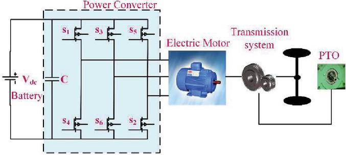
Figure 1 Schematic of battery electric tractor.
2.1 Tractive Force
Tractor requires very high torque during its operation. Tractor performance is determined by making use of parameters such as strength, rpm and torque. There are a number of forces acting on an electric tractor while in operation. The forces that act on the tractor while in operation are to be taken into consideration while performing the calculations for power and torque requirements [27, 28]. The tractor motion can be determined by analysing the forces acting on it, in the direction of motion. The forces acting on a tractor, moving up a grade are shown in Figure 2.

Figure 2 Representation of dynamic forces acting on tractor.
Instantaneous force experienced at tractor’s wheel is consider to be tractive force (Ftr). It is sum of rolling resistance of wheels, aero dynamic drag force, acceleration force and road angle gradient force as shown in Equations (1) and (2).
For tractor alone,
| (1) |
For tractor hauling trailer,
| (2) |
Where is air density (in kg/m), A is the frontal area of the tractor (in m), Cd is drag coefficient, V is velocity (in m/s), M is the mass of the tractor (in kg), Cr is rolling resistance co-efficient, g is gravitational constant (in m/s), is the inclination angle of the road surface. During farming applications tractor will operate in fields with farming implement connected behind it. An additional draft force (Df) due to ploughing tool (an implement) is added to this force is calculated based on standard formulae from the ASABE [29]. During field operations operating velocity of tractor is less and typically around 7 kmph and major farming lands are flat in level and hence no gradient exist [30]. So aerodynamic drag force and gradient forces can be neglected. The total tractive force during field operations is given by Equation (3).
| (3) |
Where F is the adjustment parameter of soil texture. For fine textured soil i 1, 2 for medium and 3 for coarse textured soils. A, B, C are the implement geometrical parameters, v is the operating velocity of tractor (in km/h), W is machine width (in meters) or number of rows, T is tillage depth (in centimeters). The implements used, specific parameters of implements and width of implements is given in Table 4.
Table 4 Parameters of farming implements
| SI Units | |||||||
| Width | Machine Parameters | Soil Parameters | |||||
| Implement | Units | A | B | C | F1 | F2 | F3 |
| Field Cultivator | tools | 46 | 2.8 | 0 | 1 | 0.85 | 0.65 |
| Chisel Plough (5 Cm straight Point) | tools | 91 | 5.4 | 0 | 1 | 0.85 | 0.65 |
| Sweep Plough | m | 390 | 19 | 0 | 1 | 0.85 | 0.65 |
| Disc Harrow | m | 309 | 16 | 0 | 1 | 0.88 | 0.78 |
| Mould Board Plough | m | 652 | 0 | 5.1 | 1 | 0.75 | 0.45 |
2.2 Torque, Power and Energy
Torque required to propel the tractor can be obtained from the tractive force. Instantaneous torque at tractor wheel is product of tractive force and driving wheel radius (). The power required at wheels is product of torque and operating velocity (). In BET electric motor transfers the torque via transmission system (fixed gear) to wheels. The electromagnetic torque , speed , and electromagnetic power required by an electric motor are calculated through gear ratio , and gear efficiency of transmission system and given by Equations (4), (5), and (6). The detailed steps involved in powertrain sizing for BET is given is Figure 3.
| (4) | ||
| (5) | ||
| (6) |
2.3 Battery
Battery is the energy house of an electric tractor. It supplies power to the traction motor to propel the tractor independently. On-board battery pack inside the tractor enables the tractor’s operation until it discharges. Once the battery pack is exhausted to its minimum level, it is charged again. Power requirement Equation (7), energy capacity Equation (8), state of charge (SOC) of battery pack Equation (9) and fuel consumption (FC) Equation (10) are depends on Pem, power converter efficiency ( converter), driving cycle time (in sec) and distance (km).
| (7) | |
| (8) | |
| (9) | |
| (10) |
Where is battery power, is power converter efficiency, is battery energy (in kWh), 0.277 is the conversion factor form MJ to kWh.
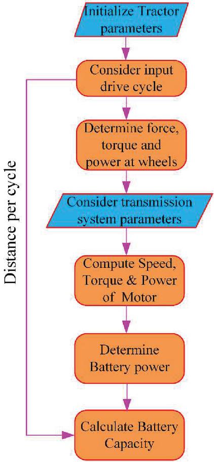
Figure 3 Steps involved in powertrain sizing of battery electric tractor.
3 Drive Cycles
It is used to find the fuel energy consumption and for comparing vehicle performances. All the standard drive cycles used to test EV are used for urban, sub urban and high way driving and these are not suited for off-road vehicles. So these drive cycles can’t be used for tractors. Tractor works with different applications, which can be differentiated by field operations and transportation work. By considering limitations of standard drive cycles, real world driving patterns are defined for tractor during field operations and trailer applications on field or rural roads. Their real world driving patterns are defined by taking data from [31, 32]. Typical predefined driving route and the correspondence speed profile for particular field operation is shown in Figures 4 and 5.

Figure 4 Driving track of tractor in farms (a), corresponding driving pattern (b).
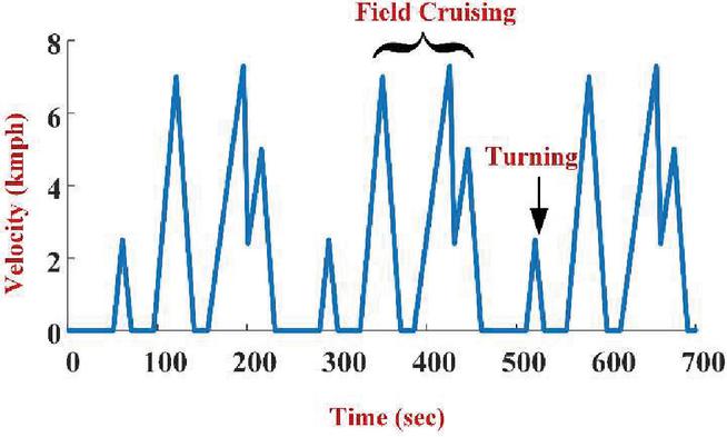
Figure 5 Driving pattern of tractor in farms with mouldboard plough.
Driving pattern for tractor hauling trailer for three different surfaces is given in Figure 6. A modified NEDC with maximum speed of 25 kmph also used for tractor hauling trailer for transportation shown in Figure 7.
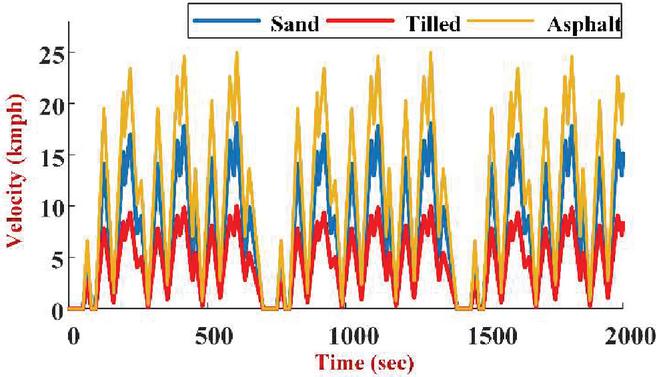
Figure 6 Driving pattern for tractor hauling trailer.
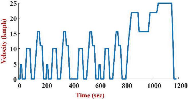
Figure 7 Modified NEDC driving pattern for tractor hauling trailer.
4 Result & Discussion
Performance of tractor powertrain is evaluated with its farming implements under repeatable conditions. The tractors operation is also analysed on the firm surface with various operating velocities with different implements. In this paper simulation of the powertrain of a small BET is performed for transport and farming applications. Driving patterns used in simulation are already discussed in previous section.
4.1 Wheel Load Analysis
Wheel load analysis includes the analysis of wheel force, wheel power and wheel energy per distance for various driving patterns. Roll resistance force depends on mass of the tractor and road surface. Driving pattern I is used for tractor hauling a trailer of 2000 kg. In this case, tillage surface requires more roll resistance force (1750 N) compared to sand (980 N) and asphalt (568 N) surfaces, since it offers less friction to wheels. In driving patterns II and III farm implements are used without trailer. Therefore the roll resistance force is reduced on the same tillage surface due to the reduction of weight of the trailer. In field, the tractor requires a maximum wheel force of 7000 N at its wheels as shown in Figure 8. The torque and power required at wheels are given in Table 5. Figure 9 gives wheel energy per distance in Wh per km. It shows that asphalt surface provides more friction to tires therefore requires less acceleration energy than other two surfaces. At same time operating velocity on asphalt surface is higher than sand and tilled surface. Therefore, it require more aerodynamic energy. During field operations draft energy requirement is very high equal to 388 Wh per km.
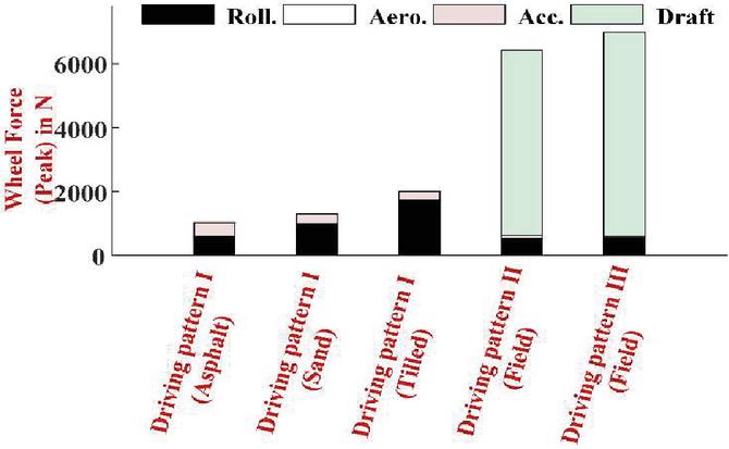
Figure 8 Peak wheel force of BET.
Table 5 Torque, power and speed requirement of BET powertrain for various driving patterns
| Motor Ratings | |||||||||||
| Requirement at Wheels | Rated | Peak | |||||||||
| Tmax | Pmax | Nmax | Trated | Prated | Nrated | Tpeak | Ppeak | Nrated | |||
| S.No. | Drive Cycle | (Nm) | (kW) | (rpm) | (Nm) | (kW) | (rpm) | (Nm) | (kW) | (rpm) | |
| 1 | Driving pattern I (Tractor hauls the trailer for transportation) | Asphalt Surface | 476 | 9.18 | 185 | 7.8 | 4.5 | 1500 | 28 | 12 | 2500 |
| Tilled surface | 608 | 8.4 | 133 | 8.2 | 5.2 | 1500 | 32 | 15 | 3300 | ||
| Sand surface | 731 | 8.4 | 110 | 6 | 4.8 | 1400 | 35 | 13.2 | 3800 | ||
| 2 | Modified NEDC | 432 | 6.5 | 185 | 5.8 | 4.3 | 1500 | 19 | 10.2 | 2500 | |
| 3 | Driving pattern II | Field operation with farming implements | 2195 | 8.78 | 51 | 21.5 | 8.6 | 2600 | 63.5 | 13.8 | 5200 |
| 4 | Driving pattern III | 2373 | 13.3 | 75 | 26 | 9.8 | 2300 | 71.2 | 21.7 | 6900 | |

Figure 9 Wheel energy per km distance for BET.
4.2 Tractor Without Implements (Tractor Hauling Trailer)
In this mode, no farm implements are attached to the tractor. Tractor hauls the trailer of weight 2000 kg for transport in tillage field, sand and asphalt surfaces with speed of 15, 18, 25 kmph respectively. Simulation is performed for 2000 s for each driving pattern namely driving patterns which is discussed in section III. Acceleration, electromagnetic torque and power requirement of motor is shown in Figure 12. Asphalt surface requires high acceleration of 0.2 m/s since speed is high, followed by sand 0.13 m/s and tillage surface 0.9 m/s. Torque and power requirement are maximum for tillage soil as its torque varies from 6.8 to 8.2 Nm and power maximum of 14.8 kW. NEDC driving pattern is modified to suit the requirement of a tractor to carry load in rural areas. This modified NEDC driving pattern has maximum speed of 25 kmph. This simulation is performed for 1183 s, which covers distance of 11.15 km per cycle. It requires an average electromagnetic torque of 6 Nm and maximum torque of 19 Nm and rated power of 4.3 kW and maximum power of 10.2 kW which are shown in Figure 13. The torque, power and speed requirements are also listed in Table 5. For driving pattern I, the energy required per km distance is 0.132, 0.140 and 0.150 Wh per km for asphalt, sand and tillage surfaces respectively. For the range of 100 km, the battery capacity required is 13.2, 15 and 15 kWh for all the three surfaces. Modified NEDC requires 0.125 Wh per km distance which is less than driving pattern I, and the battery capacity of 12.5 kWh for 100 km range. All this information is provided in Table 6.
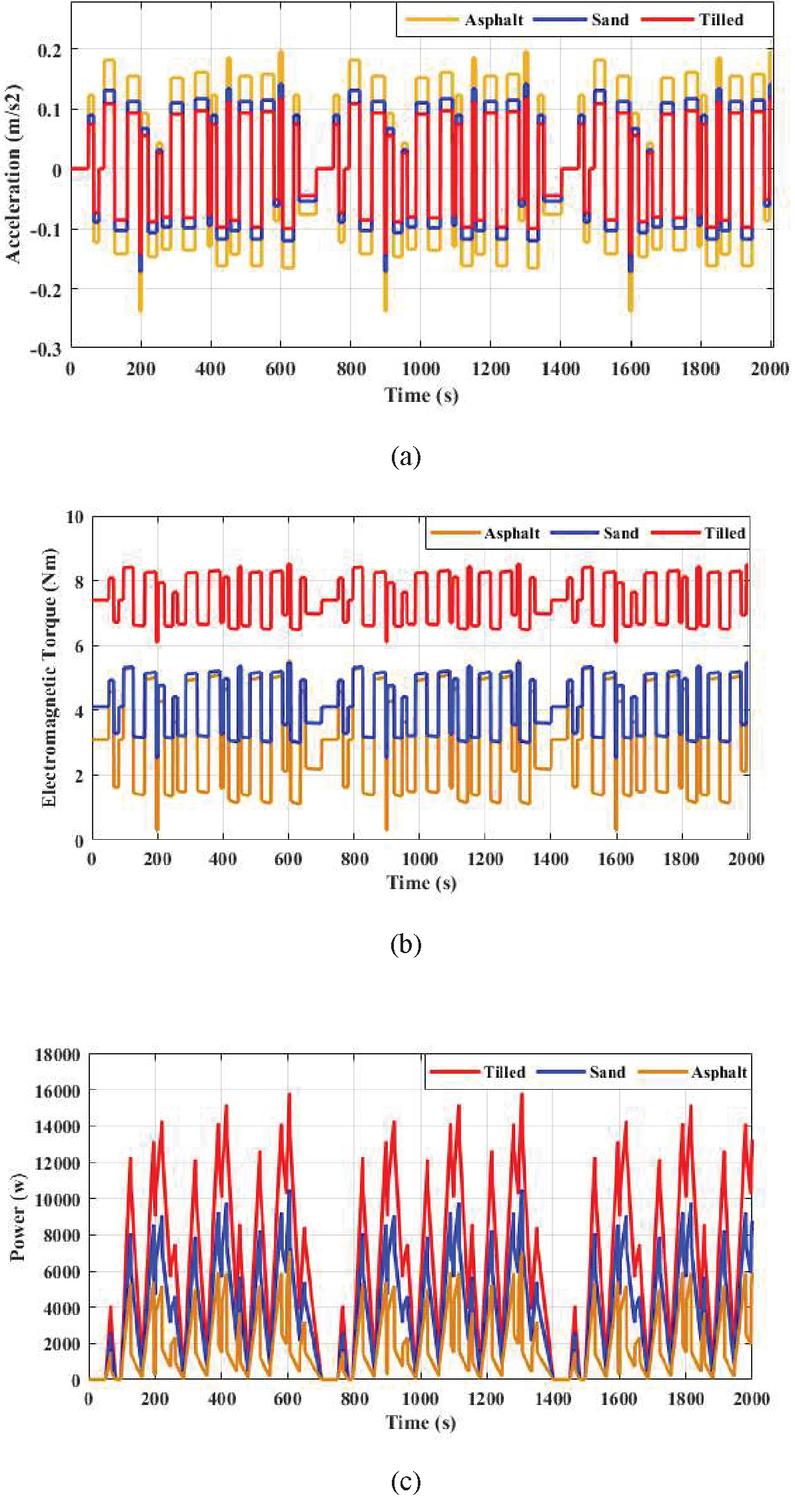
Figure 10 (a) Acceleration, (b) Electromagnetic torque and (c) Electromagnetic power of BET for driving pattern I (Transportation).
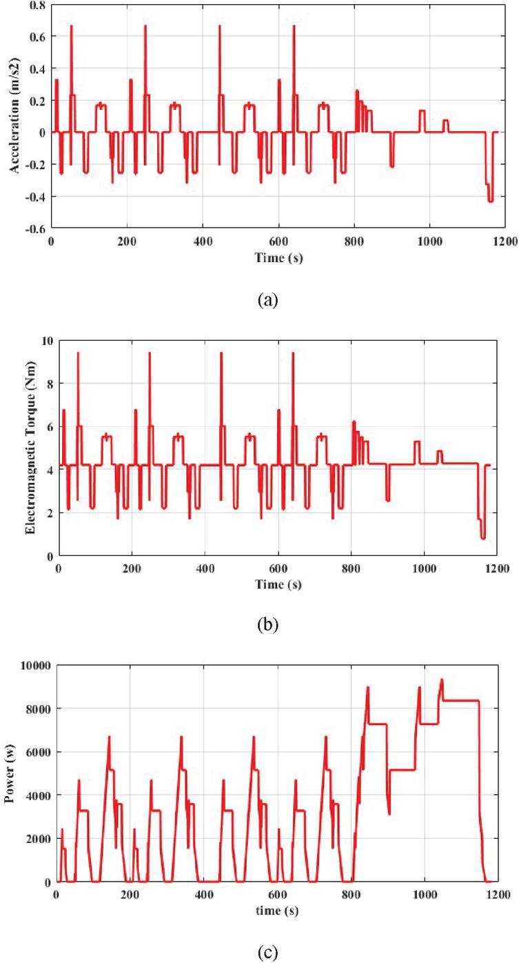
Figure 11 (a) Acceleration, (b) Electromagnetic torque and (c) Electromagnetic power of BET for Modified NEDC.
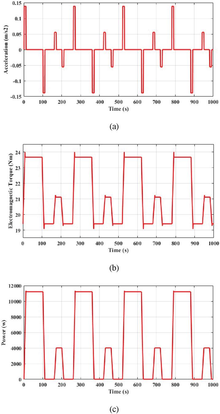
Figure 12 (a) Acceleration, (b) Electromagnetic torque and (c) Electromagnetic power of BET for driving pattern II (Field operations).
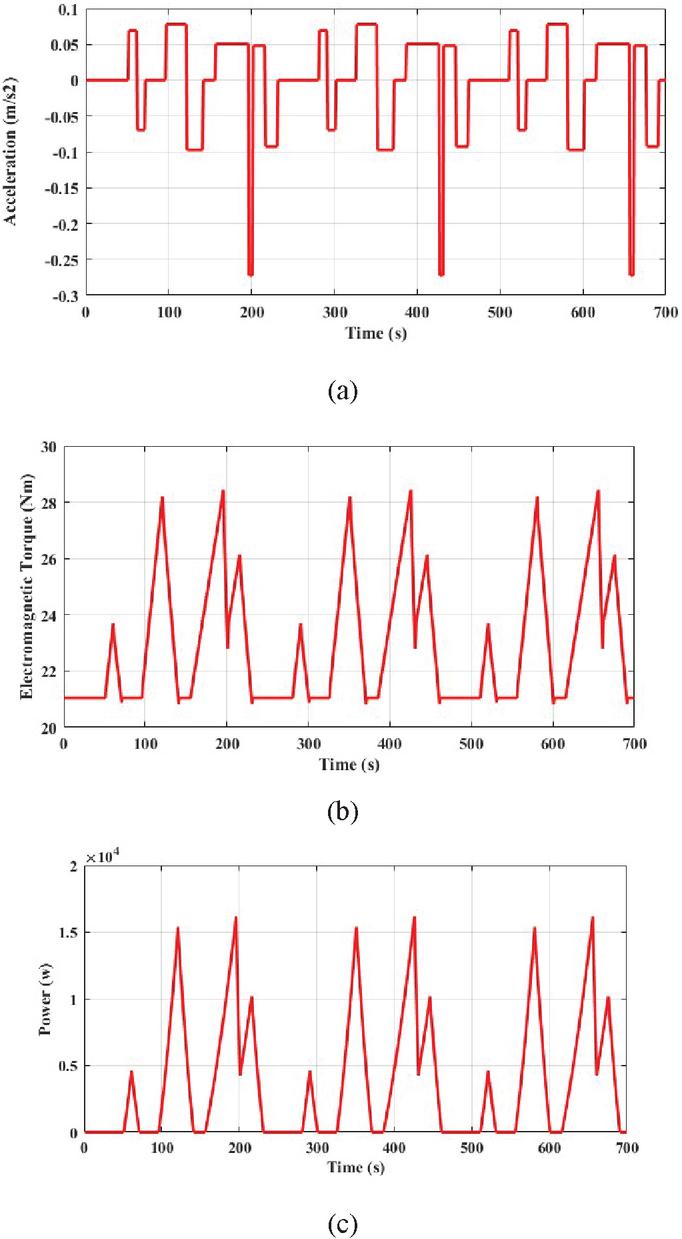
Figure 13 (a) Acceleration, (b) Electromagnetic torque and (c) Electromagnetic power of BET for driving pattern III (Field operations).
Table 6 Battery specifications of BET for various driving patterns
| Total | Average | Maximum | Motor | Motor | Energy | Battery | |||
| Distance | Speed | Speed | Continuous | Peak | Consumption Per km | Capacity for | |||
| S.No. | Drive Cycle | (km) | (kmph) | (kmph) | Power (kW) | Power (kW) | at Battery End (kWh/km) | 100 km (kWh) | |
| 1 | Driving pattern I (Tractor hauls the trailer for transportation) | Asphalt Surface | 21 | 10.7 | 25 | 4.5 | 12 | 0.132 | 13.2 |
| Tilled surface | 15 | 5.2 | 15 | 0.140 | 14 | ||||
| Sand surface | 18 | 4.8 | 13.2 | 0.150 | 15 | ||||
| 2 | Modified NEDC | 11.15 | 9.7 | 25 | 4.3 | 10.2 | 0.125 | 12.5 | |
| 3 | Driving pattern II | Field operation with farming implements | 5.6 | 2.1 | 5 | 8.6 | 13.79 | 0.472 | 47.2 |
| 4 | Driving pattern III | 4.8 | 2.3 | 7 | 9.8 | 21.77 | 0.354 | 35.4 | |
4.3 Tractor with Implements
In this BET, the powertrain analysis is carried out with implements for different farming applications. Here worst case scenario has been taken into consideration. Therefore a farming implement which requires high amount of draft force in all conditions such as primary and secondary tillage is considered. Farming implement is operated with speed of 5 kmph for driving pattern II and 7 kmph for driving pattern III. Soil tillage depth considered is 8 cm and torque is adjusted by throttle according to driving pattern. Driving pattern II requires acceleration of 0.12 m/s and negative acceleration represents reduction in operating speed at turning in the fields. Electromagnetic torque varies from 18 Nm to 23 Nm with rated value of 21 Nm. Similarly, the rated value of electric motor power is 8.6 kW and maximum power is around 25 kW as shown in Figure 12. This BET requires energy of 0.472 Wh. To cover a distance of 100 km a battery capacity of 47.2 kWh is required. Power train torque, power and speed requirements are given in Table 5 and battery requirements are given in Table 6.
Driving pattern III requires acceleration of 0.1 m/s and negative acceleration represents reduction in operating speed at turning in the fields. Electromagnetic torque varies from 20 Nm to 28 Nm with rated value of 26 Nm. Similarly, the rated value of electric motor power is 9.8 kW and maximum power is around 22 kW as shown in Figure 13. This BET requires energy of 0.354 Wh. To cover a distance of 100 km a battery capacity of 35.4 kWh is required. Power train torque, power and speed requirements are given in Table 5 and battery requirements are given in Table 6.
4.4 Traction Motor Performance
From the above calculations, a 15 kW rating of PMSM is selected as a traction motor and its performance is evaluated in MATLAB/SIMULINK. Same has been verified using real-time Hardware in loop (HIL) simulator with help of OPAL-RT (OP5700). The configuration of real-time implementation setup is depicted in Figure 14. The parameters of PMSM is given in Table 7.
Table 7 Parameters of PMSM used in BET
| Parameter | Value (Unit) |
| Stator resistance | 0.05 ohm |
| Inductance | 0.625 mH |
| Rated power | 15 kW |
| Rated Torque (Maximum) | 80 Nm(110) |
| Speed | 250 rad/sec |
| Flux linkages | 0.192 |
| pole pairs | 8 |
| Inertia | 0.014 kg-m |

Figure 14 Configuration of HIL implementation.
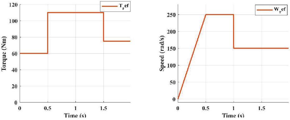
Figure 15 Torque and speed inputs for the traction motor.
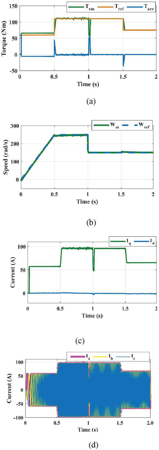
Figure 16 Simulation results of (a) Torque, (b) speed, (c) dq currents and (d) abc currents.
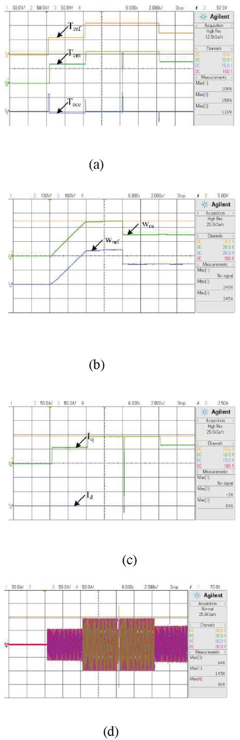
Figure 17 HIL results of (a) Torque, (b) speed, (c) dq currents, (d) abc currents.
Figure 16 shows the MATLAB results of torque, speed and currents of the traction motor for the inputs shown in Figure 15. The tractor starts accelerating and reaches to its operating velocity at t 0.5 s. After that it will maintain the same velocity (250 rad/s) till t 1 s and dropped instantly to 150 rad/s. the torque requirement during acceleration is 60 Nm, at t 1 s it increased to 110 Nm and the same is continuous till t 1.5 s drops instantly to 75 Nm. In Figure 16(a) whenever there is a difference in the reference torque (Tref) and electromagnetic torque (Tem) produced by the motor, there exists an accelerating torque (Tacc). When time t 0.5 s there is step change in the Tref and the Tem reaching with slight delay, so there is an amount of accelerating torque during that delay. Similarly at t 1 s, speed of the tractor is dropped to 150 rad/sec during that time there is small disturbance in the electromagnetic torque. Figure 16(b) shows the speed response of the tractor, the speed of the traction motor is always following the reference speed (wref), whenever there is change in wref, there is slight change (either rise or fall) in the speed of traction motor. The response of the dq currents observed in the Figure 16(c). The d-axis current is always maintained zero and the q-axis current follows the torque profile and Figure 16(d) shows the stator abc current pattern for the given torque and speed inputs. Figure 17 shows the HIL results of torque, speed and dq currents of the traction motor for the same inputs shown in the Figure 15.
The proposed work describes the sizing and simulation of powertrain of BET, which is intended for use in family farming applications. In this sense, a MATLAB-Simulink model design and verified with help of PMSM tractor motor. Similarly article [32] implemented and validated a range extended solar powered hybrid electric tractor. Article [32] requires an average power of 7.92 kw for NEDC drive cycle and 11.32 kW for farming application. Whereas the proposed model requires around 5kW for the NEDC drive cycle and 11 kW for the other farming application. The tractor model presented in [32] is designed for the commercial agricultural application whereas the proposed model is for family farming.
5 Conclusion
In electric tractor, power train plays a major role which includes motor to propel and a battery to power the motor. In this paper, sizing of the powertrain components such as motor, battery and transmission system parameters are proposed for battery electric tractor. Sizing and costing of power train will helps to select proper motor to meet the power, torque and speed requirements. Performance of the powertrain of a tractor is evaluated with its operation with farming implements under repeatable conditions. Real world driving patterns are defined for the tractor during field operations. The patterns are also defined for trailer applications on field as well as rural roads. For evaluating motor and battery ratings for various driving patterns, simulation study has been done. During trailer application, the typical operating velocities considered are 18, 15 and 25 kmph for sand, tillage and asphalt surfaces respectively. The velocity considered for ploughing operation is 7 kmph. Since electric tractors are in early stage of development, this works boosts up the research progress in BET. In future, this work may be further extended by developing better control algorithms for electric motor to achieve the required torque and power for different farm applications.
References
[1] A. Lajunen, P. Sainio, L. Laurila, J. Pippuri-Mäkeläinen, and K. Tammi, “Overview of powertrain electrification and future scenarios for non-road mobile machinery,” Energies, vol. 11, no. 5, pp. 1–22, 2018, doi: 10.3390/en11051184.
[2] S. Gorjian, H. Ebadi, M. Trommsdorff, H. Sharon, M. Demant, and S. Schindele, “The advent of modern solar-powered electric agricultural machinery: A solution for sustainable farm operations,” J. Clean. Prod., vol. 292, p. 126030, 2021, doi: 10.1016/j.jclepro.2021.126030.
[3] D. Troncon, L. Alberti, and M. Mattetti, “A Feasibility Study for Agriculture Tractors Electrification: Duty Cycles Simulation and Consumption Comparison,” ITEC 2019 – 2019 IEEE Transp. Electrif. Conf. Expo, 2019, doi: 10.1109/ITEC.2019.8790502.
[4] R. R. Melo, F. L. M. Antunes, S. Daher, H. H. Vogt, D. Albiero, and F. L. Tofoli, “Conception of an electric propulsion system for a 9 kW electric tractor suitable for family farming,” IET Electr. Power Appl., vol. 13, no. 12, pp. 1993–2004, 2019, doi: 10.1049/iet-epa.2019.0353.
[5] W. Arjharn, M. Koike, T. Takigawa, A. Yoda, H. Hasegawa, and B. Bahalayodhin, “Preliminary Study on the Applicability of an Electric Tractor (Part 1): Energy Consumption and Drawbar Pull Performance,” J. JAPANESE Soc. Agric. Mach., vol. 63, no. 3, pp. 130–137, 2001, doi: 10.11357/jsam1937.63.3\_130.
[6] W. Arjharn, M. Koike, T. Takigawa, A. Yoda, H. Hasegawa, and B. Bahalayodhin, “Preliminary study on the applicability of an electric tractor (part 2),” J. JSAM, vol. 63, no. 5, pp. 92–99, 2001.
[7] D. Troncon and L. Alberti, “Case of study of the electrification of a tractor: Electric motor performance requirements and design,” Energies, vol. 13, no. 9, 2020, doi: 10.3390/en13092197.
[8] S. M. Baek, W. S. Kim, S. U. Park, and Y. J. Kim, “Analysis of Equivalent Torque of 78 kW Agricultural Tractor during Rotary Tillage,” J. Korea Inst. Information, Electron. Commun. Technol., vol. 12, no. 4, pp. 359–365, 2019.
[9] D. H. Lee, Y. J. Kim, C. H. Choi, S. O. Chung, E. Inoue, and T. Okayasu, “Development of a parallel hybrid system for agricultural tractors,” J. Fac. Agric. Kyushu Univ., vol. 62, no. 1, pp. 137–144, 2017, doi: 10.5109/1800848.
[10] C. Dépature, W. Lhomme, A. Bouscayrol, L. Boulon, P. Sicard, and T. Jokela, “Characterisation of the electric drive of EV: on-road versus off-road method,” IET Electr. Syst. Transp., vol. 7, no. 3, pp. 215–222, 2017, doi: 10.1049/iet-est.2016.0060.
[11] M. Brenna, F. Foiadelli, C. Leone, M. Longo, and D. Zaninelli, “Feasibility Proposal for Heavy Duty Farm Tractor,” 2018 Int. Conf. Electr. Electron. Technol. Automotive, Automot. 2018, pp. 1–6, 2018, doi: 10.23919/EETA.2018.8493236.
[12] A. Das, Y. Jain, M. R. B. Agrewale, Y. K. Bhateshvar, and K. Vora, “Design of a Concept Electric Mini Tractor,” in 2019 IEEE Transportation Electrification Conference, ITEC-India 2019, 2019, pp. 10–14, doi: 10.1109/ITEC-India48457.2019.ITECIndia2019-134.
[13] H. Mousazadeh, A. Keyhani, A. Javadi, H. Mobli, K. Abrinia, and A. Sharifi, “Life-cycle assessment of a Solar Assist Plug-in Hybrid electric Tractor (SAPHT) in comparison with a conventional tractor,” Energy Convers. Manag., vol. 52, no. 3, pp. 1700–1710, 2011, doi: 10.1016/j.enconman.2010.10.033.
[14] Y. Ueka, J. Yamashita, K. Sato, and Y. Doi, “Study on the development of the electric tractor-Specifications and traveling and tilling performance of a prototype electric tractor,” Eng. Agric. Environ. Food, vol. 6, no. 4, pp. 160–164, 2013, doi: 10.1016/S1881-8366(13)80003-1.
[15] D. Troncon, L. Alberti, S. Bolognani, F. Bettella, and A. Gatto, “Electrification of agricultural machinery: A feasibility evaluation,” 2019 14th Int. Conf. Ecol. Veh. Renew. Energies, EVER 2019, pp. 1–7, 2019, doi: 10.1109/EVER.2019.8813518.
[16] M. G. Matache et al., “Small power electric tractor performance during ploughing works,” INMATEH – Agric. Eng., vol. 60, no. 1, pp. 123–128, 2020, doi: 10.35633/INMATEH-60-14.
[17] I. Yoo, T. Lee, G. Kim, B. Kim, J. Hur, and K. Yeon, “Performance interpretation method for electrical tractor based on model-based design,” 2013 Int. Conf. IT Converg. Secur. ICITCS 2013, pp. 1–4, 2013, doi: 10.1109/ICITCS.2013.6717869.
[18] P. Moreda, M. A. Muñoz-García, and P. Barreiro, “High voltage electrification of tractor and agricultural machinery - A review,” Energy Convers. Manag., vol. 115, no. x, pp. 117–131, 2016, doi: 10.1016/j.enconman.2016.02.018.
[19] L. Riedner, C. Mair, M. Zimek, T. Brudermann, and T. Stern, “E-mobility in agriculture: differences in perception between experienced and non-experienced electric vehicle users,” Clean Technol. Environ. Policy, vol. 21, no. 1, pp. 55–67, 2019, doi: 10.1007/s10098-018-1615-2.
[20] S. Y. Baek, Y. S. Kim, W. S. Kim, S. M. Baek, and Y. J. Kim, “Development and verification of a simulation model for 120 kW class electric AWD (all-wheel-drive) tractor during driving operation,” Energies, vol. 13, no. 10, pp. 1–14, 2020, doi: 10.3390/en13102422.
[21] E. A. Grunditz, Design and Assessment of Battery Electric Vehicle Powertrain, with Respect to Performance, Energy Consumption and Electric Motor Thermal Capability, vol. 59. 2016.
[22] L.-Y. Xu, X.-W. Xia, Z.-L. Zhou, H.-L. Liu, and M.-L. Wei, “Simulation and analysis for driving system of electric tractor based on CRUISE,” no. 51375145, pp. 1367–1375, 2015, doi: 10.1142/9789814730518\_0161.
[23] S. Gupta, R. Maity, and S. K. Ceng, “Modeling, analysis and experimental validation of tractor architectures for rural electrification,” SAE Tech. Pap., vol. 12, 2013, doi: 10.4271/2013-01-2784.
[24] K. Rajashekara, “Present status and future trends in electric vehicle propulsion technologies,” IEEE J. Emerg. Sel. Top. Power Electron., vol. 1, no. 1, pp. 3–10, 2013, doi: 10.1109/JESTPE.2013.2259614.
[25] Z. Yang, F. Shang, I. P. Brown, and M. Krishnamurthy, “Comparative study of interior permanent magnet, induction, and switched reluctance motor drives for EV and HEV applications,” IEEE Trans. Transp. Electrif., vol. 1, no. 3, pp. 245–254, 2015, doi: 10.1109/TTE.2015.2470092.
[26] Murali, Abhishek, Razia Sultana Wahab, Chandra Sekhar Reddy Gade, Chitra Annamalai, and Umashankar Subramaniam. “Assessing Finite Control Set Model Predictive Speed Controlled PMSM Performance for Deployment in Electric Vehicles.” World Electric Vehicle Journal 12, no. 1 (2021): 41.
[27] P. R. S. Patil et al., “Analysis of Electric Vehicle Drive Train,” IEEE Trans. Smart Grid, vol. 3, no. 1, pp. 3194–3197, 2018.
[28] H. Nagar et al., “Powertrain Sizing and Performance Evaluation for Battery Electric Vehicle Using Model Based Design,” 2021 Innovations in Power and Advanced Computing Technologies (i-PACT), 2021, pp. 1–6.
[29] American Society of Agricultural and Biological Engineers, “ASAE D497.7 MAR2011 Agricultural Machinery Management Data,” Test, p. 9, 2011.
[30] H. Mousazadeh, A. Keyhani, A. Javadi, H. Mobli, K. Abrinia, and A. Sharifi, “Optimal Power and Energy Modeling and Range Evaluation of a Solar Assist Plug-in Hybrid Electric Tractor (SAPHT),” Trans. ASABE, vol. 53, no. 4, pp. 1025–1035, 2010, doi: 10.13031/2013.32586.
[31] Y. Zahidi, M. El Moufid, S. Benhadou, and H. Medromi, “An assessment of low-cost tractor motorization with main farming implements,” World Electr. Veh. J., vol. 11, no. 4, pp. 1–35, 2020, doi: 10.3390/wevj11040074.
[32] A. Ghobadpour, H. Mousazadeh, S. Kelouwani, A. S. Malvajerdi, and S. Rafiee, “Design, development, and evaluation of a PV_Bio-Gen range extender for an off-road electric vehicle,” Int. J. Renew. Energy Res., vol. 10, no. 1, pp. 388–399, 2020.
Biographies

Chandrasekhar Reddy Gade, he is currently perusing PhD. at Vellore Institute of Technology (VIT), Vellore, Tamilnadu, India. Received M.Tech degree in Power electronics & Drives from VIT, Vellore, Tamilnadu, India in the year 2017 and B.Tech degree in Electrical and Electronics engineering from RVR & JC College of engineering, Guntur, Andhra Pradesh, India in the year 2015. His area of interest is Control of traction motors, Power electronics and industrial Drives, Electric Vehicles and special electrical machines.

W. Razia Sultana received the B.E. degree in Electrical and electronics Engineering from Madras University, Chennai, Tamil Nadu, India, in the year 2004. She received the M. Tech degree from SRM University, Tamil Nadu, India, 2006, and Doctoral degree in 2017 from VIT University, Vellore. She is currently working as Associate Professor in VIT University, Vellore, Tamil Nadu, India. Her research interests include Control of multilevel inverters, Mathematical modeling of electrical systems, and Control of high performance electrical drives, electric vehicles and special electrical machines.
Distributed Generation & Alternative Energy Journal, Vol. 38_3, 789–816.
doi: 10.13052/dgaej2156-3306.3834
© 2023 River Publishers