Droop Controller Based on Markov Chain Using Fokker-Planck Solution for a DC Microgrid
Sudhansu Bhusan Pati*, Subrat Kumar Barik and Shubhasri Kundu
School of EE, KIIT University, Bhubaneswar, India
E-mail: patisudhansubhusan@gmail.com; skbarikfel@kiit.ac.in; shubhasri.kundufel@kiit.ac.in
*Corresponding Author
Received 28 January 2022; Accepted 04 April 2022; Publication 27 February 2023
Abstract
Coordinated control of distributed energy resources in a DC micro grid is very much essential in order to meet the critical load demand. A number of control strategies including droop control, Master slave control, Local control, Adaptive control have been investigated and implemented by many researchers. However due to absence of communication link in droop control it has been extensively used in dc microgrid. However the circulating current cannot be avoided which further leads to the loss of power. In this paper an effort has been made to apply markov chain along with fokker plank solution to design the the droop control for fast response during disturbances and at the same time it will also limit the circulating current. The proposed model has been tested for a standard dc microgrid model using matlab simulink.
Keywords: Droop control, PV control, DC-microgrid, point of interconnection, bipolar.
1 Introduction
Improvement in the state of art Technology and socio-economic concern throughout the globe and demand for Clean green energy e leads to generation of distributed energy in contradiction to centralised energy production system [1, 2]. interconnection of intermittent sources of energy like solar photovoltaic system and wind system has lead to a number of problems in terms of stability therefore DISCOMS are more tending towards distributed energy sources [3, 4]. As compared to AC in systems these days the importance of the DC system is increasing because of use of Smart devices which requires DC supply [5].
Again DC micro grid is getting popular as compared to AC micro grade because of its higher efficiency to the intermittent sources reliability and stability to the critical loads connected in the system [6–8]. non conventional energy sources produce direct current at its output in contradiction to alternating current therefore use of DC source can avoid the requirement of power electronic converters while operating as an independent system [9, 10]. Most of the present day electronic devices require DC as the input therefore direct use of resources in those appliances can avoid the concept of harmonic in the AC power system and thereby reducing power quality issues in the distribution system [11, 12]. Most of the industrial drives are using DC source for their Motors so the intermittent sources like wind and Solar require only a DC to DC conversion system in contradiction to AC to DC to AC conversion system [13, 14]. Apart from the above mentioned advantages from a load point of view the DC system does not require reactive power as required in AC systems [15]. reactive components in a system usually lead to AT&T losses and thereby affecting the economy of the system. It also increases the linking capacitor in case of an inverter and makes it bulky while handling a large power transmission system or while interconnecting a DC source to the traditional AC transmission system [16, 17]. However in the DC transmission system only the active power is being transmitted from the point of generation to the point of utilisation and thereby reducing the requirement of coupling capacitor. absence of harmonics and reactive power increases the reliability of the DC distribution system. The absence of inertia in DC microgrids leads to easy operation of the system as compared to AC microgrids [18, 19].
A decentralized generation system is getting popularized throughout the globe because variation in the load can be easily handled by a local generation system without affecting the main grid. Extensive research in the field of solar photovoltaic system, wind energy system, fuel cell and battery management system has made it possible to form a stand alone microgrid system which can mitigate the local demand and can open a door for future energy requirements. Apart from the above mentioned advantages most of the country are abiding by the kyoto protocol to reduce their carbon footprint thereby the microgrid concept can lead to reduced a sufficient amount of carbon dioxide that is generated from conventional sources of energy. distributed energy sources in the form of microgrids face a lot of problems in terms of Technical challenges related to the interconnection of the sources to the load particularly during dynamic load allocation system and thereby affecting the power flow.
In case of power outage the microgrid can provide power two most of the critical loads in a grid transmission system and thereby can replace the conventional source of energy by utilising a conventional source of energy. These micro grids can operate independently by isolating themselves from the main grid during fault conditions. Therefore these microgrids are basically low voltage operating grids and have the ability to operate independently during main grid disturbances. This requires proper controlling techniques, which can improve the reliability of the system and their by supplying electrical energy for the critical loads. The absence of inertia has made it complicated to maintain the power balance among different generating units especially when the microgrids operate as an isolated system.
In order to manage different types of sensitive load particularly in a micro grid the grid must have sufficient backup to take care of the load during grid failure. Therefore the microgrid has to satisfy certain International standards such as the microwave must be insecure about the availability of microservices so as to meet the electrical loads. The micro grid also satisfies the utility standard operating procedures for interconnecting the intermittent sources to the grid particularly solar photovoltaic system and wind energy system. as a matter of fact for socio-economic concern the microgrid most sensuous a minimum emission and thereby minimising the AT&T losses. As the microgrid is a small capacity grid therefore the grid must ensure maximum utilisation of its micro resources. In order to satisfy the above condition the micro grid control action has to ensure the following points.
• In order to minimise the cost of operation and to minimise the AT&T loss the transfer of active and reactive power should match exactly the load requirement.
• Isolation from the main grid and interconnection to the main grid most satisfied the IEEE 1547 guidelines.
• The microgrid must be self tuned to brownout and can operate under black start condition during the breed disturbances.
• Different energy storage devices along with the facts controller must ensure the reliability and stability of the micro grid.
2 Droop Control Method
Unlike AC microgrid the droop control architecture of DC microgrid requires voltage-power droop control. This is in contradiction to frequency-power droop as in AC system. Any deviation in load sharing or increase in load, drops down the voltage. This causes the droop controller to increase their output power. Two types of controller i.e. both primary and secondary controller will act together in mitigating the voltage disturbances. Figure 1 shows the DC-droop controller in mitigating the disturbance.
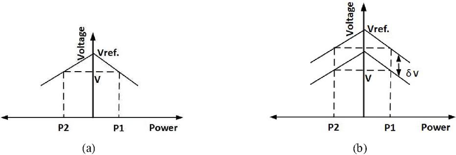
Figure 1 Droop control technique (a) primary controller (b) secondary controller.
A voltage drop due to primary controller by changing the load is shown in Figure 1(a), similarly for secondary controller the voltage drop is shown in Figure 1(b). Unlike AC grid, in DC grid, the active power always depends upon the DC link voltage and line resistance . Therefore, the power handled by the system becomes,
| (1) |
and the droop slop becomes,
| (2) |
The real power in a dc microgrid is always proportional to current, therefore voltage-current controller can be implemented either by using V-I or characteristics. Hence this linear characteristics leads to the designing of linear controller. So simplifying the (2) in terms of voltage and power it becomes,
| (3) |
From (3), during critical loading condition on the converter, the converter does not feel stress. This condition can only be satisfied by proper modelling of droop controller in term of design and stability of the controller.
A droop controller can be modeled in two different manner such as, forward droop and inverse droop [19]. The gain of the forward droop must be chosen in such a manner that it should not affect the phase margin of the current controller. So in order to avoid the unnecessary errors, in this work the inverse droop control has been used [19]. It can be noticed here that increase in droop control gain decreases the line resistance and at the same time it increases the voltage droop at the output of converter. Therefore to avoid current mismatch and voltage drop due to slope mismatch, it is required to design an higher level secondary controller or regulator. Due to the use of positive feedback in reverse droop control techniques, it does not take the input voltage into consideration. Hence a droop control technique based on Markov chain has been proposed. In the following Section, the detailed problem formulation and solution methodology related to Markov chain implementation along with droop control has been presented.
3 Modeling & Result Analysis
The performance analysis of the proposed droop controller has been investigated with a standard model as shown in Table 1. Unlike AC microgrid where control parameters are frequency, here in DC microgrid the control parameter is DC link voltage of the system. similarly the line reactance has been replaced with dc line resistance (R). Inertia in the system has been maintained by coupling capacitor (C).
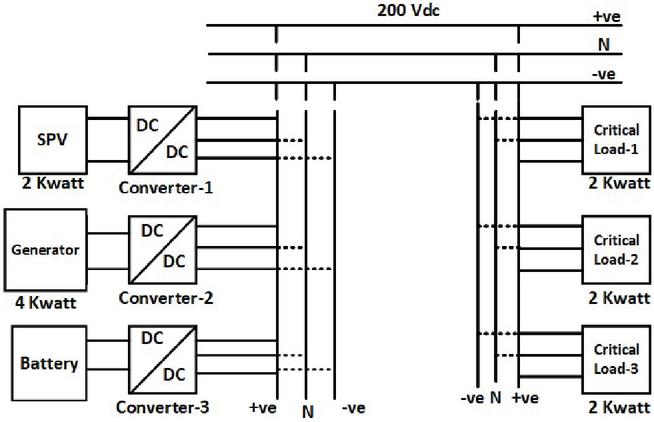
Figure 2 Standard Model of 6 Kwatt DC Microgrid.
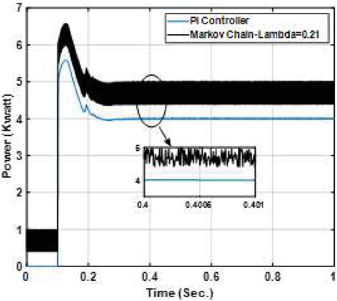
Figure 3 Power Curve with Lambda 0.21.
The Figure 2 shows the standard model of 6 kW DC microgrid and the corresponding parameter for the model is shown in Table 1. The solar Photo-voltaic (SPV) system uses a mono-crystalline architecture having open circuit voltage of 42.7 V and that of short circuit current of 7.93 A with 100 nos. of cell constitute to 2000 Wp system. Similarly the battery and the diesel generator is selected as per the requirement. Optimised lambda-1 and lambda-2 has been used in droop controlled converter, where the parameters are evaluated using Markov chain and FPS as discussed. Proportional and integral constant of the converter has been evaluated using controller design and applications of Matlab in accordance is shown in Figure 3. The critical loads as shown in Figure 3 consists of 3 parallel load of each 2 kwatt. However the load will be connected to the microgrid in a step wise manner with different rating so as to create three types of case i.e. category-1, category-2 and category-3 droop control method.
The variability of the critical load in the simulation has been achieved by synchronising the load with a ramp function bounded by [1, 1]. So each time the change is steep will be 0.03 sec. Therefore R has been evaluated to 1.37 ohm (effective-DC Resistance) by considering the slop with respect to droop-time characteristics. Again the microgrid has been modelled as bipolar system by using neutral point clamped (NPC). Parallel converter droop control technique has been applied to limit the circulating current.
Table 1 Category-1,Droop controller response time with respect to LVRT requirement [?]
| Controller Response Time | ||||
| c | c | PI-Controller | PI-Markov Chain | PI-Markov Chain-FPS |
| v 1.20 | – | 0.18 | 0.158 | 0.141 |
| 1.175 v ,1.20 | 0.2 | 0.38 | 0.307 | 0.268 |
| 1.15 v 1.175 | 0.5 | 0.62 | 0.61 | 0.57 |
| 1.10 v 1.175 | 1 | 0.58 | 0.534 | 0.523 |
| 0.88 v 1.10 | Infinite | Infinite | Infinite | Infinite |
| 0.70 v 0.88 | 4 | 0.51 | 0.48 | 0.378 |
| 0.50 v 0.70 | 0.16 | 0.33 | 0.39 | 0.319 |
| V 0.50 | – | 0.22 | 0.183 | 0.161 |
Table 1 shows the category-1, droop controller response with respect to LVRT requirements. Here it can be found that, for a voltage range between 0.88 pu to 1.10 pu all the controller behaves almost same. Any further decrease in voltage will make the PI-markov chain FPS to respond first as compared to others. When voltage falls below the 50% of reference value PI-Markov chain FPS has taken minimum time of 0.161 for its operation. Similarly when the voltage increases beyond 120% of reference value it took only 0.14 second to increase the power injection.
Table 2 Category-2,Droop controller response time with respect to LVRT requirement [?]
| Controller Response Time | ||||
| c | c | PI-Controller | PI-Markov Chain | PI-Markov Chain-FPS |
| v 1.20 | 0.18 | 0.158 | 0.141 | |
| 1.175 v ,1.20 | 0.2 | 0.378 | 0.41 | 0.252 |
| 1.15 v 1.175 | 0.5 | 0.7 | 0.56 | 0.52 |
| 1.10 v 1.175 | 1 | 2.08 | 1.98 | 1.92 |
| 0.88 v 1.10 | Infinite | Infinite | Infinite | Infinite |
| 0.65 v 0.88 | 8.7 | 17.68 | 13.05 | 11.67 |
| 0.45 v 0.65 | 0.32 | 0.338 | 0.33 | 0.317 |
| 0.3 v 0.45 | 0.16 | 0.47 | 0.368 | 0.315 |
| v 0.30 | 0.15 | 0.133 | 0.092 | |
Table 3 Category-3,Droop controller response time with respect to LVRT requirement [?]
| Controller Response Time | ||||
| c | c | PI-Controller | PI-Markov Chain | PI-Markov Chain-FPS |
| v 1.20 | 0.14 | 0.132 | 0.127 | |
| 1.1 v ,1.20 | 12 | 0.056 | 0.039 | 0.032 |
| 0.88 v 1.10 | Infinite | Infinite | Infinite | Infinite |
| 0.70 v 0.88 | 20 | 0.58 | 0.536 | 0.482 |
| 0.50 v 0.70 | 10 | 0.52 | 0.513 | 0.486 |
| v 0.50 | 1 | 0.089 | 0.074 | 0.071 |
Table 2 shows the Category-2, Droop controller response time with respect to LVRT requirement. In contradiction to category-1, in category-2 the voltage group has been divided into 9 groups. Here it can be found that when voltage level falls below 30% of the reference value the proposed controller i.e. PI-markov chain FPS provides faster response with 0.092 sec. only to increase the real power. Like category-1 analysis, here also for voltage level between 0.88 to 1.10 pu all the three controllers will provide same time of operation.
Table 3 shows the Category-3, Droop controller response time with respect to LVRT requirement. In category-3 the voltage group has been divided into 6 groups. As seen from the Table 3 that when voltage falls below 50% of the reference value PI-markov chain FPS provides faster response with 0.071 sec, which is more than 22% efficient as compared to conventional PI controller.
The real power curve response of the proposed markov chain FPS for lambda 0.21 is shown in Figure 3. Here it can be found that the amount of power delivered by the PI controller has been increased up to 4.7 kWatt. Again as soon as the system detects change in voltage level, the controller increases the power delivered level in 0.05 sec as compared to 0.19 sec in conventional PI controller. Again the incorporation of markov chain introduces some more samples in the response ultimately creating a small variations, which can be mitigated by using a small DC filter. Here in this paper we have taken an average of the fluctuation which is coming around 4.725 kWatt.
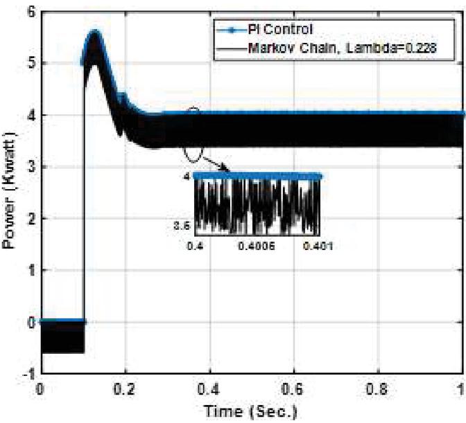
Figure 4 Power Curve with Lambda 0.228.
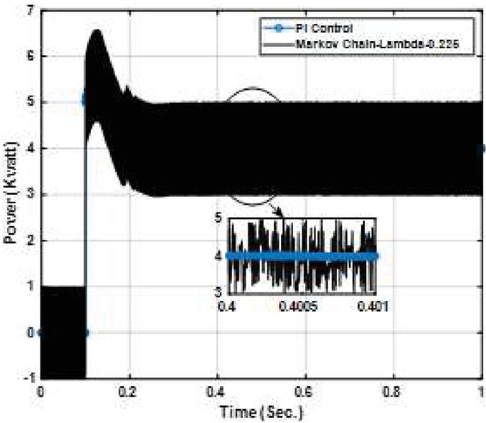
Figure 5 Power Curve with Lambda 0.226.
Similarly, the real power curve response of the proposed markov chain FPS for lambeda 0.228 is shown in Figure 4. Here it can be found that with lambda 0.228 the performance of the system is slightly sluggish because the drop controller first decreases the power from the reference level and then it will increase the power. Figure 5 shows the real power curve response of the proposed markov chain FPS for lambda 0.226. Here also the system shows sluggish performance. Therefore, in this system we have taken 0.2 as the lambda value for simulation and validation of the controller.
Figure 6, shows the stability analysis of the controller with step input. The classical PI controller shows a maximum overshoot of 142% as that of Markov chain with lambda 0.227. Hence from stability point of the proposed controller is also superior as compared to classical and classical PI and Markov chain PI.
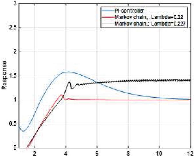
Figure 6 Stability analysis of controllers.
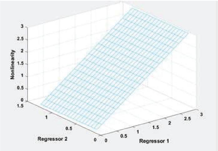
Figure 7 ARX model evaluation.
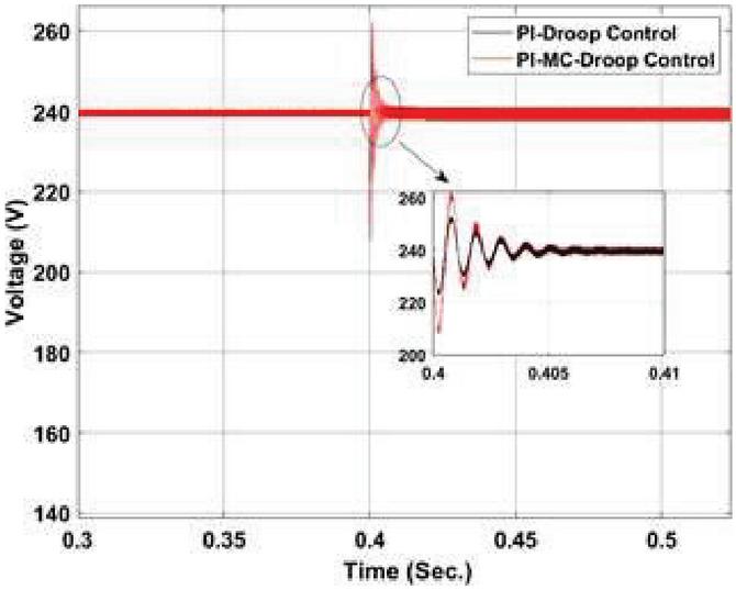
Figure 8 Droop control characteristics for voltage (Category-1).
Figure 7 shows the ARX model to evaluate the lambda-1 and lambda-2 value. Figure 8 represents the droop control characteristics for voltage under Category-1. Here it can be found that a terminal voltage of 240 V is maintained until a disturbance of change in critical load at 0.4 sec. occurs in the system. The system under goes six oscillations with highest deviation of 260 V before comes down to stable voltage i.e. 240 V in this case. However, by using the modified droop controller it can be noticed here that a maximum deviation of 249.3 V occurs as compared to previous one with lambda value of 0.226. Hence the stability of the system is also improved and that of the reliability.
Figure 9 shows the droop control characteristics for voltage under Category-2. Here it can be found that during fault a sudden decrease in voltage occurs at 0.4 sec with decrease in magnitude of 130 V. stability in the system has been achieved after 0.04 sec. In contradiction, PI-Markov chain with FPS can stabilize the system within 0.02 sec as shown in the Figure 9.
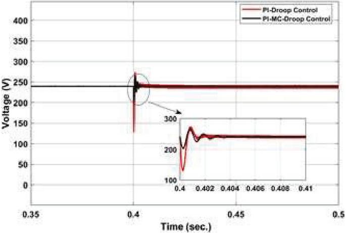
Figure 9 Droop control characteristics for voltage (Category-2).
Table 4 Comparative analysis of the controller(s) with step input for stability analysis
| Parameter | PI Controller | PI-Markov Chain | PI-Markov Chain FPS |
| Rise Time | 0.08 | 0.063 | 0.06 |
| Pick Time | 0.097 | 0.072 | 0.071 |
| Settling Time | 4.2 | 3.27 | 3.20 |
| Maximum over shoot | 1.23 | 1.14 | 1.07 |
| steady state | 4.61 | 4.027 | 3.881 |
| error stability | marginally stable | stable | stable |
Table 4 shows the Comparative analysis of the controller(s) with step input for stability studies. Here it can be found that both PI-markov chain and PI-markov chain FPA are stable with unit step function. The steady state error is also less as compared to classical PI and PI-markov chain which is 3.881 in this case.
4 Conclusion
A comprehensive analysis of three different types of droop control system viz. PI controller, PI-Markov Chain and PI-Markov Chain with FPS, exclusively applicable to DC microgrid has been presented in this paper. Based on the result analysis as discussed above it is found that for different voltage range the PI-Markov Chain with FPS provides better result which has been explained from Tables 1 to 3. In all the cases as seen that, the system behaves perfect under a voltage range of 088 p.u to 1.10 p.u.
Again, the proposed method consists of inverse droop control which ultimately increases the output power when there is an decrease in terminal voltage of the converter. It also increases the reference voltage at the output due to absence of input voltage.due to presence two controlling parameter such as lambda-1 and lambda-2 in addition to the single PI controller, therefore the method is more robust and controllable in terms of its accuracy. The proposed method can be implemented without the use of centralized controller.
References
[1] F. Ktiraei, R. Iravani, N. Hatziargyriou, and A. Dimeas, “Microgrids management-controls and operation aspects of microgrids,” IEEE Power Energy, vol. 6, no. 3, pp. 54–65, May 2008.
[2] R. H. Lasseter and P. Piagi, “Microgrid: A conceptual solution,” in Proc. IEEE Power Electron. Specialists Conf., Aachen, Germany, Jun. 2004, pp. 4285–4291.
[3] H. Nikkhajoei and R. H. Lasseter, “Distributed generation interface to the CERTS microgrid,” IEEE Trans. Power Del., vol. 24, no. 3, pp. 1598–1608, Jul. 2009.
[4] N. Hatziargyriou, Microgrids: Architectures Control. Hoboken, NJ, USA: Wiley, Mar. 2014.
[5] M. Farrokhabadi et al., “Microgrid stability definitions, analysis, and examples,” IEEE Trans. Power Syst., vol. 35, no. 1, pp. 13–29, Jan. 2020.
[6] M. E. Baran and N. R. Mahajan, “DC distribution for industrial systems: Opportunities and challenges,” IEEE Trans. Ind. Appl., vol. 39, no. 6, pp. 1596–1601, Nov. 2003.
[7] N. Eghtedarpour and E. Farjah, “Control strategy for distributed integration of photovoltaic and energy storage systems in DC micro-grids,” Renew. Energy, vol. 45, pp. 96–110, Sep. 2012.
[8] L. Xu and D. Chen, “Control and operation of a DC microgrid with variable generation and energy storage,” IEEE Trans. Power Del., vol. 26, no. 4, pp. 2513–2522, Oct. 2011
[9] N. Eghtedarpour and E. Farjah, “Distributed charge/discharge control of energy storages in a renewable-energy-based DC micro-grid,” IET Renew. Power Gener., vol. 8, no. 1, pp. 45–57, Jan. 2014.
[10] B. Dong, Y. Li, Z. Zheng, and L. Xu, “Control strategies of microgrid with hybrid DC and AC buses,” in Proc. IEEE 14th Eur. Conf. Power Electron. Appl., Birmingham, U.K., Aug. 2011, pp. 1–8.
[11] A. Karabiber, C. Keles, A. Kaygusuz, and B. B. Alagoz, “An approach for the integration of renewable distributed generation in hybrid DC/AC microgrids,” Renew. Energy, vol. 52, pp. 251–259, Apr. 2013.
[12] K. Kurohane, T. Senjyu, A. Uehara, A. Yona, T. Funabashi, and C.-H. Kim, “A hybrid smart AC/DC power system,” in Proc. IEEE 5th Conf. Ind. Electron. Appl., Jul. 2010, pp. 764–769
[13] J. Hu, Y. Shan, Y. Xu, and J. M. Guerrero, “A coordinated control of hybrid AC/DC microgrids with PV-wind-battery under variable generation and load conditions,” Int. J. Electr. Power Energy Syst., vol. 104, pp. 583–592, Jan. 2019.
[14] D. E. Olivares, A. Mehrizi-Sani, A. H. Etemadi, C. A. Cañizares, R. Iravani, M. Kazerani, A. H. Hajimiragha, O. Gomis-Bellmunt, M. Saeedifard, R. Palma-Behnke, G. A. Jiménez-Estévez, and N. D. Hatziargyriou, “Trends in microgrid control,” IEEE Trans. Smart Grid, vol. 5, no. 4, pp. 1905–1919, Jul. 2014.
[15] A. Mohammed, S. S. Refaat, S. Bayhan, and H. Abu-Rub, “AC microgrid control and management strategies: Evaluation and review,” IEEE Power Electron. Mag., vol. 6, no. 2, pp. 18–31, Jun. 2019.
[16] S. Parhizi, H. Lotfi, A. Khodaei, and S. Bahramirad, “State of the art in research on microgrids: A review,” IEEE Access, vol. 3, pp. 890–925, Jun. 2015.
[17] F. Nejabatkhah, Y. W. Li, and H. Tian, “Power quality control of smart hybrid AC/DC microgrids: An overview,” IEEE Access, vol. 7, pp. 52295–52318, Apr. 2019.
[18] Ritesh Dash, Sarat Chandra Swain,Effective Power quality improvement using Dynamic Activate compensation system with Renewable grid interfaced sources, Ain Shams Engineering Journal, Volume 9, Issue 4, 2018, Pages 2897–2905.
[19] R.R. Hete, Sanjoy Kumar Mishra, Ritesh Dash, Adithya Ballaji, Vivekanandan Subburaj, Kalvakurthi Jyotheeswara Reddy, Analysis of DFIG-STATCOM P2P control action using simulated annealing techniques, Heliyon, Volume 8, Issue 3, 2022.
Biographies

Sudhansu Bhusan Pati completed Btech in EEE branch in the year 2007. M.Tech from SOA University in the year 2012 with Power electronics and Drives Specialization. Presently he is the research scholar at School of EE, KIIT Deemed to be University, Bhubaneswar. His research Interest includes Dc Microgrid, Solar PV cell and Battery and its characteristics.

Subrat Kumar Barik has sixteen years of experience in teaching in undergraduate and postgraduate level. He has also excellent research. career in the area of Solar Photovoltaic Grid Integrated System. He has a number of research publications in SCI, Scopus indexed journals and international conferences. He graduated in the year 2002 from the VSSUT Burla in Electrical Engineering discipline, receives master’s degree from KIIT Deemed to be University in 2008 and PhD degree in 2015 from SOA University and currently working as an Associate Professor in School of Electrical Engineering KIIT University, Bhubaneswar, Odisha, India.

Shubhasri Kundu was born in 1985, W.B India. Presently working as Assistant Professor (II) in School of Electrical Engineering, KIIT DU. She has received her B.Tech in Electrical Engineering from Jalpaiguri Govt. Engineering College in 2007. She completed her M.Tech(Research) in 2012 Ph.D. in Mechanical Engineering in 2016 from NIT, Rourkela. Her recent research interests are focused on Robotics Control, Design of Electrical Vehicles etc.
Distributed Generation & Alternative Energy Journal, Vol. 38_3, 907–922.
doi: 10.13052/dgaej2156-3306.3838
© 2023 River Publishers