Four Speed Auto Transmission DC-DC Converter Control for E-Vehicle and Regenerative Braking Based on Simulation and Model Investigation
S. Saahithi1,*, B. Hemanth Kumar2, K. Jyotheeswara Reddy1, Ritesh Dash1 and Vivekanandan Subburaj3
1Reva University, Bangalore, India
2Sree Vidyanikethan Engineering College, Tirupathi, India
3National Institute of Technology, Silchar, India
E-mail: sahithi.suresh@gmail.com
*Corresponding Author
Received 29 January 2022; Accepted 11 July 2022; Publication 27 February 2023
Abstract
A novel single input multioutput (SIMO) output DC-DC converter with circular capacitors is intended to function with a single independent source to create numerous transmissions to regulate the speed at the same switching intervals. A novel single input multi output (SIMO) output DC-DC converter employing circular capacitors is designed to work with a single independent source to create numerous transmissions. The proposed converter generates 7 outputs in total, with 4 outputs generated simultaneously for forward operation (speed transmission) using the preferred source (fuel cell/battery) and 3 other different outputs used for regenerative transmissions, with the battery being the preferred storage device. This converter can control the speed of an electric vehicle (EV) by using the SIMO is output voltage to regulate the vehicle is speed, allowing for higher accelerations and decelerations with minimal energy loss and degradation of the main battery pack. It can also be used to power electronic components such as LED lights, audio systems, and mobile charging etc. The energy recovered during regenerative braking is used to charge the battery via a buck/boost operation for varied speed transmission. In addition, simulation, modelling, and analysis are used to validate the proposed system. It is intended for a fixed voltage of 12 V and output voltages ranging from 12 to 48 V. The PSIM simulation tool is used to validate the system. The validation demonstrates the suggested converter is good evidence in both braking and regenerative braking operations.
Keywords: Switched capacitor converter, DC-DC converter, single input multi output, E vehicle.
1 Introduction
In recent years, E vehicle (EV) plays a vital role in the means of transport in recent years. According to the international transport forum [8], due to rapid increase in urbanization the CO2 emissions will increase around 60% by 2050 which causes global warming. One of the main reasons for the introduction of EVs is the concern about greenhouse gas emissions and their contribution to the reduction of such harmful gas emissions. EVs have a lot of potential to reduce greenhouse gas emissions. There are two types of electric cars: plug–in hybrid electric vehicles (PHEV) and battery electric vehicles (BEV). The bat tery electric cars utilize energy to operate an electric motor and are powered by a battery pack. Similarly, with plug-in hybrid electric cars, an internal combustion engine is utilized to power the vehicle in addition to the battery pack. An electric vehicle’s fundamental components are a battery, a DC-DC converter, a power electronic controller, and a traction motor. Similarly in plug-in hybrid electric vehicles along with the battery pack, an internal combustion engine is also used to power the vehicle. The basic components of an EV are battery, DC-DC converter, a power electronic controller, and a motor for traction purpose. Similarly, smart vehicle are developed to overcome the conventional EV [13]. The smart vehicle are used with IOT based control, renewable [24] and nonrenewable based input sources to the EVs are currently used. Also, mechanical speed control are widely used and studied based on clutch control [16–18], automatic transmission control [6, 15], and gear shift control [17]. To make a efficient regenerative braking and speed transmission control, electrical control will be preferred and fast. In this work, electrical based DC-DC speed control technique is used for controlling the speed of the E-vehicle. The DC-DC converter is used for controlling the speed of the EV and it is used for controlling other electronic devices in the EV system. For simplicity E-bike is considered for the discussion. For controlling the DC motor [5], DC-DC converter is required. Switched capacitor (SC) converter possess more advantages as compared to the conventional converters because the converter only uses switches and capacitors for the conversion operation, also these converters provides high efficiency and maximum target voltages but the inductor based converters [14] provides a good solution but have some limitations like EMI issues and iron losses. SC converters are widely used in many applications. High and medium power applications can also benefit from these switched capacitor DC–DC topologies [22]. For efficient conversion of DC to AC power, the output of such DC–DC converters is provided to DC–AC inverters to get AC voltage by regulating the inverter with relevant PWM methods [10–12]. Renewable energy sources are connected to the grid via high and medium power DC–DC converters. The general converter topology is considered i.e, single input multiple output (SIMO) switched-capacitor DC-DC converter is designed for speed transmission. In EV, battery is used for the acceleration of the vehicle using the DC-DC converter, i.e., it converts the fixed DC power from the battery to the variable DC which can be used by various part of the circuit and to drive the DC Motor in the vehicle. The SC converter is designed in such a way that, to maintain the voltage ripple and maintain the negative current [13] The main advantage of the proposed speed control system controls both acceleration/deceleration operation for both motoring and regenerative operation also used to control different electronic components in the vehicle.
1.1 Regenerative Braking
In an electrical vehicle, regenerative braking also helps to extend the vehicle’s range. The kinetic energy is transformed to electrical energy during the regenerative braking cycle [23]. The driving range may be extended by using regenerative braking, which also increases braking efficiency. Many different types of study have been done on regenerative braking in the recent literature [7, 21, 23], but the four transmission system completely auto controller is not mentioned in many of them. A novel four-transmission system for forwarding and regenerative operation is explored in this paper. The suggested system’s regenerative braking technology is shown in Figure 1.
2 Multi Output DC-DC Converter for Speed Transmission
Figure 2 illustrates the proposed DC-DC converter. It’s essentially a switched capacitor (SC) converter [19], with four capacitors and 14 switches linked in a circle with a single source as input (V or V) in the circuit’s centre. Different output nodes can be used to link the numerous outputs (V–V) to the load. At each node, the output is connected across the output capacitor at the same time. Both step-up (acceleration) and step-down (deceleration) voltages are achievable with the proposed converter.
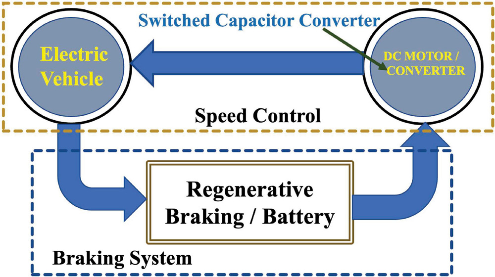
Figure 1 Configuration of regenerative braking system.

Figure 2 Multi output DC-DC converter for Speed control.
The voltage ratios that are obtained by this converter are (), (2), (3), (4), (0.5) and (0.33). Table 1.1 shows the switching sequences for both forwarding and regenerative operation. The bidirectional switches are driven by two phases with a 50 % duty cycle ratio. The charging state is phase (), while the discharging condition is phase (). The output voltage ratios are produced by charging and discharging the flying capacitors in series and parallel combinations. The speed transmission or voltage ratios are given in Table 1.1 and the speed transmission switching details are also discussed. Here, the input voltage, is considered as 12 V. For the 1st transmission, the output voltage V. Similarly, for the 4th transmission the output voltage V. To generate the different speed transmission following switching sequence need to be considered. For simplicity (3) speed transmission is considered. Phase 1 involves charging the capacitors and in parallel with and turning on the switches , , and . Similarly, in phase 2, the capacitors and are linked in series with the voltage source and the negative terminal of the capacitor is connected to the voltage source, and the same capacitor is connected in series with through switches , , , and . The stored energy is given back to the battery via the proposed converter during regenerative braking. In Table 1, ‘P’ denotes a 50% positive half cycle, ‘N’ denotes a 50% negative half cycle, and ‘1’ denotes a switch that is always ON.
Table 1 Acceleration and deceleration of speed transmission switching pattern
| Switches/Speed | ||||||||||||||
| Transmission | S | S | S | S | S | S | S | S | S | S | S | S | S | S |
| V | P | N | – | – | – | – | – | – | – | – | – | – | – | – |
| 2V | – | – | N | P | P | N | N | – | – | – | – | – | – | – |
| 3V | – | – | N | P | P | N | – | P | P | N | – | N | – | – |
| 4V | – | – | N | P | P | N | – | P | P | N | P | N | P | N |
| 1V | N | P | – | – | – | – | – | – | – | – | – | – | – | – |
| 0.5V | – | – | – | – | – | N | 1 | – | N | P | N | – | N | P |
| 0.33V | – | – | – | 1 | N | P | N | – | N | P | N | – | N | P |
| 0.25V | 1 | – | P | N | N | P | N | – | N | P | N | – | N | P |
2.1 Proposed Converter Loss Analysis
When building a SC converter [9], one of the most essential parameters to consider is equivalent resistance. For the sake of simplicity, voltage ratios of (3) are used in the analysis. Figures 3 and 4 depict the analogous circuit for the voltage ratio (3). The power loss [14] in any i operational phase is provided as,
| (1) |
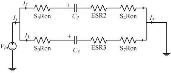
Figure 3 Proposed equivalent circuit of charging state (3).

Figure 4 Proposed Equivalent Circuit of Discharging state (3).
Assume that all switch resistances are the same and that parasitic effects (ESR) for all flying capacitors are the same. In addition, as compared to the flying capacitor capacitance (, , , ), the filter capacitor capacitance (, , , ) is high. The current equation is given in (2)–(4) using the technique outlined in [3], the charge balance equation, and nodal KCL analysis for phases and as shown below,
| (2) | ||
| (3) | ||
| (4) |
The capacitor charging and discharging equation is obtained from Figures 3 and 4 and is given in (5)–(8).
| (5) | |
| (6) | |
| (7) | |
| (8) |
The [14] is calculated by combining (5), (6), (7), and (8) and it is given by,
| (9) |
Similar steps are followed for solving R for other voltage ratios. The R of other voltage ratios is given in Table 2 [25].
Table 2 Equivalent resistance of four speed transmission
| Voltage | Model | Simulated |
| Ratios | ||
| V | 4.16 | 4.13 |
| 2V | 4.16 | 4.14 |
| 3V | 5.20 | 5.18 |
| 4V | 6.94 | 6.93 |
Table 3 Comparison results of , and speed transmission
| Frequency | Voltage | Model | Analysis | Simulated |
| kHz | Ratios | (V) | (V) | |
| 100 | V | 11.99 | 11.95 | 11.95 |
| 100 | 2V | 23.99 | 23.94 | 23.94 |
| 100 | 3V | 35.98 | 35.95 | 35.95 |
| 100 | 4V | 47.98 | 47.93 | 47.93 |
3 Simulation and Case Study of Proposed Converter
In this work, only electrical speed transmission control is designed using existing mechanical braking systems [7, 18, 21]. The proposed converter is simulated using PSIM tool and it is validated using the model which is designed using bidirectional switch and the parameters of the MAX4678 switches S – S are R [20] referring to the Figure 2. The load current varies from 2 mA to 1 A at a voltage of 12 V for the different voltage ratios, and the flying capacitor and output capacitor are rated at 22 F with an ESR of 100 m, 220 F with a load resistance of 5 k, and the load current ranges from 2 mA to 1 A at a voltage of 12 V. The comparative findings of the model (V), simulated (V), and theoretical voltages (V) of the 3V ratio are shown in Table 3. The simulations are carried out under the following scenarios.
Case 1: Proposed converter outputs (V to ) is connected to elec tronic loads.
Case 2: One of the output is connected to EV (Motor Load) and the remaining outputs are connected to electronics load.
Case 3: Regenerative voltage fed back to the .
i. Case 1
In this scenario, the electronic load is linked to all of the proposed converter’s loads. The output voltage and voltage ripple of the 3 voltage ratio is shown in Figure 5, with a voltage ripple of 0.1 V. All of the simulated output voltages are almost identical to the model values, as shown in Figure 6. The simulated output voltage of 3V is 35.97 V, as shown in Figure 7, and it is evident that the simulated output voltage is nearly similar to the model voltages. In addition, the load variation for the suggested converter is shown in Figure 5 by altering the resistance value from 5 k to 1 k for the voltage ratio 3V. By comparing the findings of (V), (V) and (V) values that are in excellent agreement with each other, the suggested converter is concluded.

Figure 5 Load variation of (3).
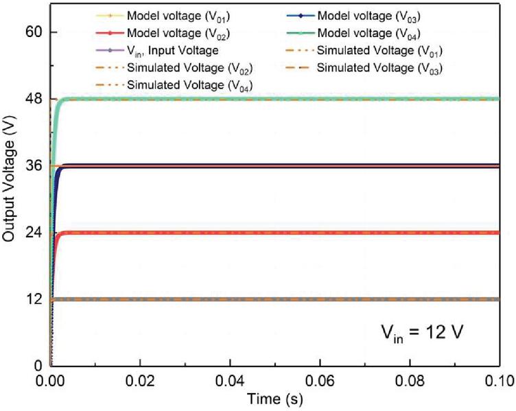
Figure 6 Comparison of speed transmission voltage with model voltage.

Figure 7 Simulation of proposed converter output voltage for 3 mode.
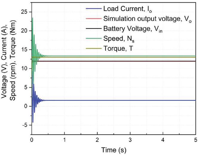
Figure 8a: Simulated output voltages of E-vehicle when motor load is connected at output terminal.

Figure 8b: Parameter design using Bicycle model.
ii. Case 2
The parameters of torque, speed, and the current are assumed using t and f. Assumption are made for designing the E vehicle parameters. The parameters are motor/gear is 3 kg, controller is 0.5 kg, battery 3 kg and the cyclist is 10 kg. Let us considered the real time parameter of a bicycle where the speed, V is 5 km/hr, F is 13 Nm, P is 18 W, head wind speed is 1 km/hr and adding 2 W power to propel then P is 20 W. When designing the EV, real-time factors are taken into account. Assume the EV’s power and torque is constant. Figure 8 depicts the proposed converter’s simulated output voltage when the load is connected to the motor. It provides the efficient results of output voltage 11.98 V, load current 1.68 A, torque is 13 Nm, input voltage is 12 V, speed is 13.6 RPM. From this, it is clear that even motor load is connected to the proposed converter it provides efficient operation.

Figure 9 Simulated output voltage of regenerative braking [25].
iii. Case 3
The energy from the EV is supplied back to the source during regenerative braking using the same suggested converter, which will serve as a buck operation for charging the battery utilizing different step down voltage ratios. For the sake of simplicity, regenerative operation is assumed to be (0.3V), and the pulse pattern is shown in Table 1. If the regeneration voltage is less than the source voltage (i.e., the battery voltage), the proposed converter would charge the battery as a boost operation. When regenerative braking is operational, Figure 9 displays the simulated output voltage of the proposed converter. Figure 10 depicts the total efficiency of the proposed converter for both forwarding and regenerative operation. Table 4 shows the overall comparison of different factors with previous research studies. As a result, the suggested converter has a higher efficiency, fewer switches and capacitors, and lower voltage ripple. In addition, the suggested converter would operate in both forwarding and regenerative modes without requiring any changes to the circuit architecture. In this simulation, switched capacitor converter provides high efficiency [20] in open loop conditions as shown in the Figure 10. So the closed loop system is not necessary for the proposed system for manual transmission. To make more efficient and speedy operation closed loop operation may be considered for automatic switching in Case 3. Furthermore, loading and unloading are left for further studies. The comparison results of proposed topology with other switched capacitor speed controller converter is shown in Table 4.
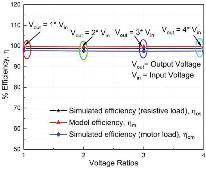
Figure 10 Efficiency of Proposed Converter [25].
Table 4 Comparison results with other switched capacitor speed controller converter [25]
| No of | No of | No of | No of | Voltage | ||
| Authors | Switches | Inputs | Outputs | Capacitors | Regenerative | Ratios |
| [1] | 3 | 1 | 2 | 2 (with inductors) | No | 2 |
| [2] | 9 | 4 | 3 | 3 (with inductors) | No | 3 |
| [4] | 7 | 1 | 1 | 3 | No | 2 |
| This work | 14 | 1 | 4 | 4 | Yes | 10 |
4 Conclusions
The proposed speed transmission system provides the speed control in E-Vehicle (EV) for higher accelerations and deceleration. The transmission control is also used to control regenerative braking, which uses slowdown or acceleration to feed energy back into the battery. In addition, simulation, modelling, and analysis are used to ensure that the proposed system delivers optimum efficiency and effective braking actions. The four transmission speed control is designed using 14 switches and 4 capacitors. The efficiency of the proposed system is more than 90% when the bicycle load is considered and the speed is 13 RPM and the measured torque is 15 Nm. In addition, this proposed converter can be used both in fuel cell and the battery systems. The main advantage of this system is multiple speed transmission (1, 2, 3 times of the input voltage) is possible by performing different charging operation of the capacitors in different switching pattern.
References
[1] IA Aden, Hakan Kahveci, and Mustafa Ergin Şahin. Single input, multiple output DC-DC buck converter for electric vehicles. Turkish Journal of Electromechanics & Energy, 2(2):7–13, 2017.
[2] Faraz Ahmad, Aziz Ahmad Haider, Hassan Naveed, Atay Mustafa, and Irshad Ahmad. Multiple input multiple output DC to DC converter. In 2018 5th International Multi-Topic ICT Conference (IMTIC), pages 1–6. IEEE, 2018.
[3] Shmuel Ben-Yaakov. On the influence of switch resistances on switched-capacitor converter losses. IEEE Transactions on Industrial Electronics, 59(1):638–640, 2011.
[4] Ormond D Castle and Adel El Shahat. Single-input-multi-output (simo) converter for nano-grids applications. In SoutheastCon 2017, pages 1–5. IEEE, 2017.
[5] Nicola Dal Bianco, Roberto Lot, and Koen Matthys. Lap time simulation and design optimisation of a brushed DC electric motorcycle for the isle of man tt zero challenge. Vehicle System Dynamics, 56(1):27–54, 2018.
[6] Shengnan Fang, Jian Song, Haijun Song, Yuzhuo Tai, Fei Li, and Truong Sinh Nguyen. Design and control of a novel two-speed uninterrupted mechanical transmission for electric vehicles. Mechanical Systems and Signal Processing, 75:473–493, 2016.
[7] Yimin Gao, Liping Chen, and Mehrdad Ehsani. Investigation of the effectiveness of regenerative braking for ev and hev. SAE transactions, pages 3184–3190, 1999.
[8] How to make urban mobility clean and green. http://www.internationaltransportforum.org, 2018.
[9] G. Indira Kishore and Ramesh Kumar Tripathi. High gain single switch DC-DC converter based on switched capacitor cells. Journal of Circuits, Systems and Computers, 29(12):2050188, 2020.
[10] B. Hemanth Kumar, Makarand M. Lokhande, Raghavendra Reddy Karasani and Vijay B. Borghate. A Modified Space Vector PWM Approach for Nine-Level Cascaded H-Bridge Inverter. Arabian Journal for Science and Engineering (AJSE), 44(3):2131–2149, 2019.
[11] Busireddy Hemanth Kumar, Makarand Mohankumar Lokhande, Karasani Raghavendra Reddy, and Vijay Bhanuji Borghate. An improved space vector pulse width modulation for nine-level asymmetric cascaded H-bridge three-phase inverter. Arabian Journal for Science and Engineering, 44(3):2453–2465, 2019.
[12] B. H. Kumar and M. M. Lokhande. An enhanced space vector PWM for nine-level inverter employing single voltage source. 2017 IEEE Transportation Electrification Conference (ITEC-India), pp. 1–6, 2017, doi: 10.1109/ITEC-India.2017.8333711.
[13] Amari Mansour, Bacha Faouzi, Ghouili Jamel, and Elgharbi Ismahen. Design and analysis of a high frequency DC–DC converters for fuel cell and super-capacitor used in electrical vehicle. International journal of hydrogen energy, 39(3):1580–1592, 2014.
[14] Vivekanandan Subburaj, Ainur Zhaikhan, Debashisha Jena, Parthiban Perumal, Yerzhan Mustafa, and Alex Ruderman. Investigation of a family of dual-output coupled/decoupled switched capacitor converter for low-power applications. IET Circuits, Devices & Systems, 13(3):352–360, 2018.
[15] Yang Tian, Jiageng Ruan, Nong Zhang, Jinglai Wu, and Paul Walker. Modelling and control of a novel two-speed transmission for electric vehicles. Mechanism and Machine Theory, 127:13–32, 2018.
[16] Yang Tian, Nong Zhang, Shilei Zhou, and Paul D. Walker. Model and gear shifting control of a novel two-speed transmission for battery electric vehicles. Mechanism and Machine Theory, 152:103902, 2020.
[17] Yang Tian, Nong Zhang, Shilei Zhou, and Paul D Walker. Model and gear shifting control of a novel two-speed transmission for battery electric vehicles. Mechanism and Machine Theory, page 103902, 2020.
[18] Paul Walker, Bo Zhu, and Nong Zhang. Powertrain dynamics and control of a two speed dual clutch transmission for electric vehicles. Mechanical Systems and Signal Processing, 85:1–15, 2017.
[19] C. D. Xu, K. W. E. Cheng, and Y. M. Ye. A topology of step-down resonant switched-capacitor-based AC–DC converter for high-frequency ac distribution. Journal of Circuits, Systems and Computers, 24(10):1550154, 2015.
[20] Ainur Zhaikhan, Vivekanandan Subburaj, Debashisha Jena, Parthiban Perumal, and Alexander Ruderman. Design, modeling and analysis of a new dual input-output switched capacitor converter. In TENCON 2017-2017 IEEE Region 10 Conference, pages 673–677. IEEE, 2017.
[21] Junzhi Zhang, Chen Lv, Jinfang Gou, and Decong Kong. Cooperative control of re-generative braking and hydraulic braking of an electrified passenger car. Proceedings of the Institution of Mechanical Engineers, Part D: Journal of Automobile Engineering, 226(10):1289–1302, 2012.
[22] Hemanth Kumar B, Bhavani A, Jeevithesh CV, Padmanaban S, Subburaj V. A New Series-Parallel Switched Capacitor Configuration of a DC–DC Converter for Variable Voltage Applications. In Electric Vehicles, pages 247–270, Springer, 2021.
[23] Junzhi Zhang, Chen Lv, Mingzhe Qiu, Yutong Li, and Dongsheng Sun. Braking energy regeneration control of a fuel cell hybrid electric bus. Energy conversion and management, 76:1117–1124, 2013.
[24] Kumar BH, Subburaj V. Integration of RES with MPPT by SVPWM Scheme. Intelligent Renewable Energy Systems: Integrating Artificial Intelligence Techniques and Optimization Algorithms, 8:157–178, 2022.
[25] H. V. Gandhodi, K. T. R. Konkala, R. K. Bandameeda, J. Chaviti, P. K. Yenna, and V. Subburaj. A new single input-multiple output switching converter using circular capacitors for e-vehicle applications. In 2020 IEEE Region 10 Symposium (TENSYMP) (pp. 1696–1699). IEEE. Chicago (2020).
Biographies

S. Saahithi, received her B.Techdegree in electrical and electronics engineering from JNTUH and M.Tech from School of Electrical Engineering, MSRIT, VTU, Bangalore. She has more than 10 years of teaching experience. She served as Assistant Professor in Osmania university, Hyderabad. She worked as research associate at IISc, Bangalore in the field of Nano technology and fabrication.
Presently working as Assistant Professor at REVA University, Bangalore. She has a research experience of over 4 years and has sound knowledge in the field of Powe Converters, Industrial Drives and Soft Computing techniques. She has published research papers both in International Journal and Conference.

B. Hemanth Kumar received his B.Tech degree in Electrical and Electronics Engineering from Narayana Engineering College (NRNG), Gudur, India, in 2012; and his M.Tech degree in Instrumentation and Control Systems from Sri Venkateswara University (SVU), Tirupathi, India, in 2015, and the Ph.D. degree from Visvesvaraya National Institute of Technology, Nagpur, India in 2020. During his Ph.D work, he was working on development of Multilevel Inverter Control strategies and its applications. He has authored and co-authored more than 14 publications in reputed International Journals (SCI & Scopus Indexed Journals) and conferences. Currently, he is working as an Assistant Professor in the Department of Electrical and Electronics Engineering, Sree Vidyanikethan Engineering College since June 2019. He is a member of IEI. He served as Conference organizer, Session Chair, Technical Program Committee, reviewer of many reputed journals including IEEE/Elsevier/Springer etc. His current research interests include Inverter Control Strategies, Electric Vehicle, Renewable energy systems and Switched Capacitor Converters.

K. Jyotheeswara Reddy has more than 7 years of teaching experience in various reputed institutions/universities. He has actively participated in all the academic and administrative activities at various levels and produced succeeded results in academia and research. He completed his Bachelor degree from JNTU-Kakinada and Master’s degree from Sathyabama University, Chennai. He completed his Ph. D degree from VIT University. He served as an Associate Professor in Sree Vidyanikethan Engineering College, Tirupathi. Presently, he is working as an Associate Professor in School of Electrical and Electronics Engineering, REVA University-Bangalore. He has authored and coauthored more than 15 publications in reputed International Journals (SCI & Scopus Indexed Journals) and conferences.
He is a member of IEEE and IAENG. He served as Conference organizer, Session Chair, Technical Program Committee, reviewer of many reputed journals including IEEE/Elsevier/Springer etc. His research area includes Power Electronic Converters, Renewable Energy Sources and Electric Vehicles.

Ritesh Dash, received his Ph.D from School of Electrical Engineering, KIIT University and presently working as Associate Professor at REVA University, Banglore. He has a research experience of over 10 years and has sound knowledge in the field of Artificial Intelligence, FACTS and Machine learning. He has published more than 100 numbers of research papers both in International Journal and Conference. Earlier he has also published a book under CRC press. He has also served the Govt. of India as a Design Engineer, Electrical at WAPCOS Ltd. A Central PSU under Ministry of Water Resources & Ganga Rejuvenation. His current research interests include Artificial Intelligence and Machine learning in high voltage engineering applications.
He has received Madhusudan Memorial Award and Institutional Award from the Institution of Engineers, India. He is associated with Many International Bodies such as IEEE, Indian Science Congress, The Institution of Engineers, Solar Energy Society of India, Carbon Society of India and Many More.

Vivekanandan Subburaj received the B.E. and M.E. degrees in electrical and electronics engineering from Anna University, Chennai, India, in 2011 and 2013, respectively, and the Ph.D. degree from the Electrical and Electronics Engineering Department, National Institute of Technology Karnataka (NITK), Mangalore, India, in 2019. He awarded University Rank Holder in his M.E degree. He was with NITK, where he was involved in low power circuit design. Further, He served as an Associate Professor in REVA University, Bengaluru, India. He joined the Electrical Engineering department, NIT Silchar, India, in 2022, where he is currently an Assistant Professor. His current research interests include low-voltage DC–DC converter topology design with particular emphasis on low power electronics for portable computing and power management IC and power chargers.
V. Subburaj was the recipient of the Best Paper Award in Asia Flagship Conference TENCON 18. He is the Member of IEEE. He served as Editorial board member of many conference committees. Published his research articles in high impact journals such as, IEEE Transaction, IET, Elsevier etc. He served as guest editor for SCOPUS and Web of Science Journals. He organized Scopus index conferences, IEEE conferences and supported many workshops and training programs conducted by the government organization.
Distributed Generation & Alternative Energy Journal, Vol. 38_3, 987–1006.
doi: 10.13052/dgaej2156-3306.38312
© 2023 River Publishers