Optimization of the Fast Frequency Regulation Strategy for Energy Storage-Assisted Photovoltaic Power Stations
Jiayun Zhou
School of Control and Computer Engineering, North China Electric Power University, Changping 102206, Beijing, China
E-mail: 2423976220@qq.com
Received 24 October 2023; Accepted 22 November 2023; Publication 31 January 2024
Abstract
Photovoltaic (PV) power generation is characterized by randomness and intermittency, resulting in unpredictable fluctuations in output power. This presents a significant challenge to the stable operation of the grid. To address this issue, the integration of energy storage systems provides a solution to mitigate the volatility of PV output, ensuring stability and precise control. In this study, we propose an ASS-Elman-based equivalent droop control strategy for PV power stations participating in grid frequency regulation. Furthermore, a joint PV-energy storage frequency regulation system is developed. For energy storage power stations actively engaged in grid frequency regulation, we employ an adaptive droop control strategy to enhance the traditional droop control method by incorporating additional frequency control strategies. We validate the effectiveness of the proposed strategies through simulation using MATLAB/SIMULINK. The results demonstrate that these strategies maximize the potential of energy storage and PV systems to comprehensively regulate frequency and significantly improve primary frequency regulation performance.
Keywords: Primary frequency regulation, photovoltaic energy storage hybrid system, equivalent droop control, adaptive droop control.
1 Introduction
The deployment of photovoltaic (PV) power generation has been consistently increasing alongside the commissioning of high-capacity DC projects [1]. As a consequence, the frequency security issue in the power grid has become more apparent. Unlike conventional power generation methods, PV power generation connects to the grid through power electronic converters, which isolates its active power output from the grid frequency. As a result, it is unable to provide frequency support comparable to synchronous generators during system disturbances and power imbalances. Furthermore, the inability to increase power output leads to a reduction in system inertia and primary frequency regulation capability [2]. Currently, in the realm of frequency regulation with PV, a literature-recommended approach called static droop control has emerged [3, 4]. This technique emulates the primary frequency regulation method employed by synchronous machines to participate in frequency regulation. Static droop control supplements active power in response to grid frequency deviations by utilizing a fixed slope droop curve with a predefined deadband. Both simulations and real-world experiments have shown that the implementation of droop control effectively prevents a decline in system frequency and minimizes steady-state frequency deviations.
Based on previous studies [5], it has been proposed to incorporate PI control into droop control to achieve unbiased frequency regulation. However, the inclusion of the integral component leads to a deviation of the actual output of the photovoltaic system from the system dispatch command, which poses challenges in grid dispatch. In response to this, another study [6] has developed a comprehensive frequency control strategy that combines shedding control with virtual inertia control and droop control. This strategy aims to provide frequent support services. To validate the dynamic performance of this strategy, three extreme frequency decline scenarios are designed. The results demonstrate the effectiveness of this approach, showing faster tracking speed (below 50ms) and superior tracking accuracy (steady-state error below 1%). However, it is important to note that current photovoltaic frequency control systems generally lack real-time adjustability of the slope of the droop curve, resulting in limited flexibility and adaptability. As a result, the full potential of photovoltaic frequency control remains untapped.
Moreover, the integration of photovoltaics into power system frequency regulation increases the costs associated with photovoltaic power generation. The output power is susceptible to random fluctuations, which compromises the reliability of frequency regulation. To address these limitations and mitigate the volatility of photovoltaic power generation, energy storage systems offer a solution.
Based on the existing literature [7], a photovoltaic-energy storage hybrid system has been developed. This system utilizes the flexible charging and discharging capabilities of the energy storage system, enabling it to exhibit external characteristics similar to conventional synchronous machines. As a result, it can provide a rapid response speed and high control accuracy. The energy storage system prioritizes the primary frequency regulation task of the system, ensuring that the photovoltaic system can consistently output maximum power while minimizing curtailment. Extensive research has been conducted by various scholars on control strategies for energy storage-assisted photovoltaic power plants in their participation in primary frequency regulation [8–13]. Literature [14, 15] suggests incorporating droop control into energy storage power plants to participate in frequency regulation, similar to the primary frequency regulation method used by synchronous machines. This approach effectively mitigates steady-state deviations during primary frequency regulation. However, the decoupling of droop control from grid frequency changes hinders improvements in the rate of frequency change and maximum frequency deviation. Meanwhile, literature [16] employs virtual inertia control to address the insufficient inertia of wind power generation, resulting in enhanced rates of frequency change and maximum frequency deviation. However, it does not address steady-state frequency deviations. Further research is necessary to investigate integrated strategies that can simultaneously address both steady-state and dynamic frequency deviations.
Consequently, literature [17] attempts to integrate virtual inertia control with droop control by establishing the switching boundary as the maximum frequency deviation. This approach aims to reconcile the conflicts arising from the two control strategies. However, it inadequately addresses the management of energy storage’s charging status and exhibits limited adaptability, increasing the risk of excessive charging and discharging.
Based on the aforementioned research, this paper presents a novel frequency regulation scheme that integrates load- shedding control. The conventional droop control used in photovoltaic frequency regulation systems is replaced with an SSA-Elman-based equivalent droop control, enabling real-time adjustment of the droop curve slope. By combining this proposed control strategy with load shedding, the resultant system effectively mitigates frequency deviations caused by sudden changes in system load and varying solar radiation levels. Additionally, the flexibility in charging and discharging of energy storage systems is leveraged to establish a hybrid photovoltaic energy storage frequency regulation system, rectifying the limitations of standalone photovoltaic participation in frequency regulation. The introduced adaptive droop control strategy, along with the enhancements introduced via auxiliary frequency control, enables accurate tracking of the charging status and frequency variations, preventing potential issues of overcharging or over-discharging in energy storage.
To validate the proposed strategy, simulations are performed using a MATLAB/Simulink model. The obtained results confirm that the strategy outlined in this paper is capable of harnessing the full potential of energy storage and photovoltaic systems for comprehensive frequency regulation, significantly improving the primary frequency regulation capability of the system.
2 Photovoltaic Power Generation Plays an Active Role in the Rapid Frequency Regulation
2.1 Active Power-Frequency Droop Control
The photovoltaic frequency regulation system [18], as depicted in Appendix A1, consists primarily of a photovoltaic array, boost converter, grid-tied inverter, and their respective control systems. This system is designed based on the active power-frequency static characteristics of synchronous generators. Through the use of load-shedding control, the photovoltaic frequency regulation system actively participates in grid frequency regulation. This is achieved by modifying the original control structure of the boost converter to maintain a specific level of active power reserve. The mathematical expression describing this mechanism is presented in Equation (1).
| (1) |
The equation represents several variables. The coefficient “k” denotes the frequency adjustment factor, represents the value of the frequency response action. represents the initial power value, and signifies the maximum power output of photovoltaic generation.
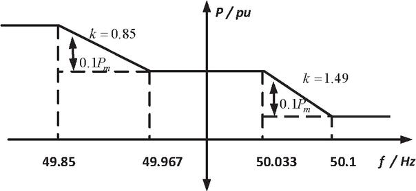
Figure 1 Active power-frequency characteristic curve.
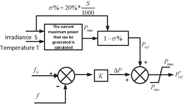
Figure 2 Active power-frequency droop control strategy [21].
Figure 1 illustrates the active power-frequency droop characteristic curve, which includes a deadband ranging from 49.967 to 50.033 Hz and a power limit of . Additionally, Figure 2 presents the modified control strategy for the Boost converter. In this strategy, the power error signal undergoes PI control to generate the duty cycle (d) needed to regulate the operation of the Boost converter. This paper introduces the concept of the reserve power ratio (%) of photovoltaic generation. During power-limited operation, the active power output of photovoltaic generation constitutes (%) of the total power output. Mathematically, % can be expressed as:
| (2) |
The curtailment level of a photovoltaic power plant directly affects its capacity to engage in primary frequency regulation. As sunlight weakens, the curtailment level decreases, diminishing the reserve capacity available for primary frequency regulation and limiting its participation ability. Conversely, as sunlight strengthens, the curtailment level increases, expanding the reserve capacity for primary frequency regulation and improving its participation ability. To minimize curtailment and maintain an ample margin for photovoltaic frequency regulation, it is commonly recommended to set the curtailment capacity between 10% and 20% [18, 20].
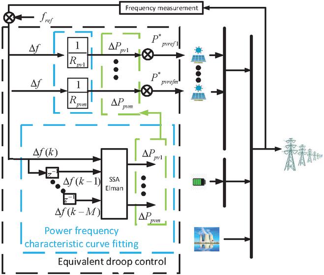
Figure 3 Equivalent droop control.
This paper presents an alternative droop control strategy, called the equivalent droop control, for photovoltaic frequency regulation systems. The proposed strategy combines SSA-Elman with curtailment control of photovoltaic power plants, serving as a replacement for the traditional active power-frequency droop control. The study begins by obtaining a new power-frequency characteristic curve for the photovoltaic primary frequency regulation system using SSA-Elman. The effectiveness of SSA-Elman is then validated by comparing its fitting performance with GWO-Elman and WOA-Elman. Subsequently, the equivalent droop control based on SSA-Elman is implemented in place of the conventional droop control in the photovoltaic frequency regulation system. Finally, simulation experiments are conducted to examine the superiority of the proposed equivalent droop control strategy over the traditional droop control strategy.
This research primarily utilizes data derived from the adaptive droop control [22], which includes both power-frequency experimental data and relevant power-frequency characteristic data obtained from the “Implementation Rules for Grid Operation and Management of Power Plants in the Northeast Region” [23]. The collected data is used as training and testing datasets for neural networks to effectively model the power-frequency characteristics of photovoltaic power plants. Subsequently, the trained neural network model can replace the conventional droop control method, allowing for equivalent droop control of photovoltaic units within the power system. Furthermore, this dataset is employed for training and testing the neural network’s ability to forecast the active power output of the photovoltaic power plant during frequency regulation.
To enhance prediction accuracy, the input is expanded from solely considering the current frequency deviation to incorporating a sequence of frequency deviations that includes both the current and historical values. This shift from a one-dimensional input to a multidimensional input is aimed at achieving superior results. At the k-th moment, the neural network employs the SSA-Elman algorithm to process input data . The network receives input signals and produces output signals indicating the change in active power for each photovoltaic unit.
2.2 Elman Neural Network
2.2.1 ENN
The Elman neural network algorithm [24] is a dynamic type of neural network that improves upon the standard backpropagation (BP) neural network. It possesses a unique structure, as illustrated in Figure 4, which defines the neural network architecture of the Elman network.
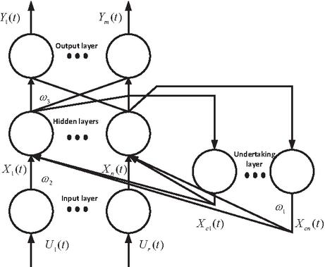
Figure 4 Elman neural network.
The Elman neural network is improved by inserting a context layer between the hidden layer and the output layer. The primary function of this context layer is to store the output information from the hidden layer of the previous time step and then feed it back as the input signal to the hidden layer again. This effectively introduces a delay operator, which allows for a delayed transmission of both input and output. Consequently, the system gains the capability to adapt to time-varying characteristics. The mathematical representation of the Elman neural network model is expressed through its functional form.
| (3) | |
| (4) | |
| (5) |
In the equation, “a” represents the self-connection feedback gain factor, “f(x)” and “g(x)” denote the activation functions of the hidden layer and output layer, respectively, while “w1, w2, w3” represent the connection weights between the layers. The error function of the Elman neural network is defined in Equation (6), and the weight adjustment error function of the network at time “t” is defined as follows:
| (6) |
In the equation, the variable and signifies the expected output, whereas represents the actual output of the i-th output node.
2.2.2 SSA
The Sparrow Search Algorithm (SSA) is a swarm intelligence optimization algorithm proposed in recent years. It is inspired by the foraging and evading behaviors of sparrows in nature. In comparison to other swarm intelligence optimization algorithms, SSA excels in its capacity to explore unexplored areas and evade local optima. It showcases remarkable stability and rapid convergence. The initial position of each sparrow is represented by Equation (7).
| (7) |
In the equation, “N” represents the number of sparrows, and “d” denotes the dimension of the variables to be optimized. The expression for the fitness value in the Sparrow Search Algorithm is shown in Equation (8).
| (8) |
In the equation, represents the fitness values of each individual. The Sparrow Search Algorithm imitates the foraging behavior of a sparrow flock to choose the top Np individuals with the best positions as explorers, while the remaining (N-Np) individuals function as followers. The position update formula for the explorers is described by Equation (9) during each iteration.
| (9) |
In the given sentence, the term “” represents the maximum number of iterations. The variable “a” is a randomly generated number within the range of (0, 1]. The symbol “” denotes the d-th dimension of the t-th individual in the population. The letter “Q” represents a random number generated from a standard normal distribution. The value of “” is a uniformly distributed random number between 0 and 1. The threshold value is denoted by “ST”. The equation for updating follower positions is presented as Equation (10).
| (10) |
Whereas “” represents the optimal position among the sparrow population, “” represents the poorest position among the current population. The following is the position update formula for the scouts responsible for thorough reconnaissance:
| (11) |
Where is the step size control parameter, which is a random number following a standard normal distribution. K is a uniformly distributed random number. is a small constant introduced to prevent division by zero and avoid errors. is the fitness value of the global best position in the current sparrow algorithm iteration, and is the fitness value of the worst position among the current sparrows.
2.2.3 ENN-SSA
The performance of the Elman neural network algorithm is greatly affected by the initial values of the weights and thresholds in each layer. However, SSA demonstrates high optimization efficiency, good stability, and fast convergence when dealing with high-dimensional problems. In this study, SSA is employed to improve the weights and thresholds of the Elman neural network, aiming to address the issue of uncertainty in the algorithm. The principle of the Elman neural network optimized with SSA is as follows:
Firstly, let’s consider the partial derivative of concerning .
| (12) |
Similarly, we calculate the partial derivative of the error function concerning the weight . By applying the chain rule , we can derive the SSA-Elman neural network learning algorithm. The calculation process is outlined as follows:
| (13) | |
| (14) |
During the regression prediction process, the historical data of power frequency in the photovoltaic frequency regulation system undergoes preprocessing. Subsequently, the Sparrow Search Algorithm (SSA) is utilized to enhance the Elman neural network, enabling the determination of optimal weights and thresholds. Finally, the preprocessed power-frequency data is fed into the optimized Elman network to achieve accurate predictions of active power in photovoltaic frequency regulation and accomplish equivalent droop control.
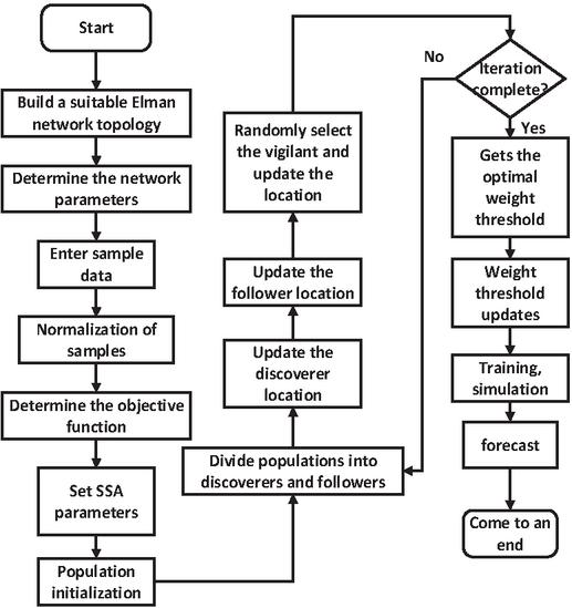
Figure 5 Photovoltaic power prediction based on SSA-Elman.
This paper aims to validate the superior performance of the Sparrow Search Algorithm (SSA) in optimizing the Elman neural network when compared to other swarm intelligence optimization algorithms. To achieve this objective, both the Whale Optimization Algorithm [25] and the Grey Wolf Optimization Algorithm [26] (detailed in Appendix A) are employed as alternatives to SSA. The objective is to optimize the training of the Elman neural network for the power-frequency characteristic curve of the photovoltaic coupling system, and simulation results are utilized for comparison. The test set consists of 1,500 samples with dimensions matching the input-output of the training dataset, where each sample has 10-dimensional input and a 1-dimensional output.
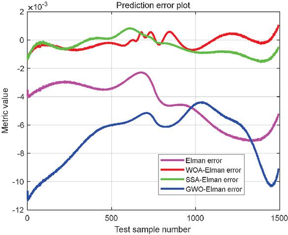
Figure 6 Prediction error.
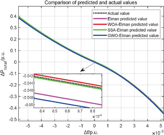
Figure 7 Fitting curve graph.
As demonstrated in Figures 6 and 7, the utilization of the Sparrow Search Algorithm (SSA) to optimize the Elman neural network yields the most favorable training results compared to other swarm intelligence optimization algorithms. Consequently, the SSA-Elman model is selected to replace the traditional droop control method in the photovoltaic coupling system. The subsequent section will focus on validating the effectiveness of the equivalent droop control strategy.
2.3 Simulation Experiment
This section aims to verify the effectiveness of the SSA-Elman-based equivalent droop control strategy by constructing a simulation model of the optoelectronic coupling system depicted in Figure 8 using the MATLAB/Simulink simulation platform. The diagram illustrates a thermal power unit of 600 MW and a photovoltaic power station of 200 MW. The simulation incorporates rated values for power, frequency, and other parameters to evaluate the system’s response to source-side and load-side disturbances. Further details regarding the simulation parameters are extensively provided in Table 1.
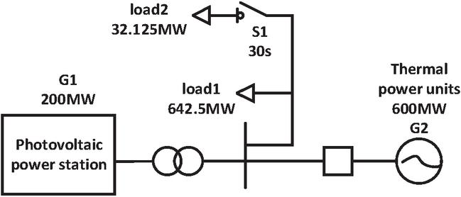
Figure 8 Optical-electrical coupling system simulation model.
Table 1 Experimental parameters of the optical coupling system
| Parameters | Numerical Value |
| The maximum output power of a single photovoltaic power plant. | 200 MW |
| Number of photovoltaic power plants in the experiment. | 1 |
| The output power of thermal power generator units. | 600 MW |
| Simulation period. | 1e–4s |
Case 1
In the optoelectronic coupling system, the initial load is 642.5 MW, and at 30 seconds, the load undergoes a sudden increase of 60 MW. The grid frequency under traditional droop control and equivalent droop control based on SSA-Elman is illustrated in Figure 9. The droop gain of the photovoltaic power station is depicted in Figure 11, while Figure 10 presents the output power.
From Figure 9, it is evident that the implementation of the equivalent droop control strategy leads to a steady-state frequency value of 49.83 Hz, with the lowest frequency point reached in 35.57 seconds. Conversely, using the traditional droop control method yields a steady-state frequency value of 49.80 Hz, with the lowest frequency point reached in 36.80 seconds. As such, the results of the simulation experiment confirm the effectiveness of the proposed equivalent droop control method based on SSA-Elman, demonstrating a significant improvement in frequency regulation quality.
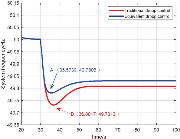
Figure 9 System frequency.
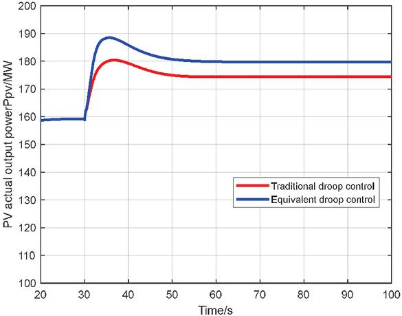
Figure 10 Actual output power of the photovoltaic power plant.
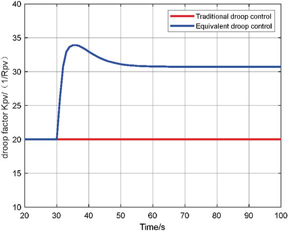
Figure 11 Droop gain.
Case 2
The solar irradiance is depicted in Figure 12. Figure 13 shows the grid frequency under traditional droop control and equivalent droop control, while Figures 14 and 15 display the droop gain and output power of the photovoltaic system, respectively.

Figure 12 Solar irradiance.
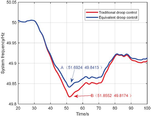
Figure 13 System frequency.
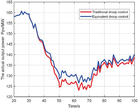
Figure 14 Actual output power of the photovoltaic power plant.
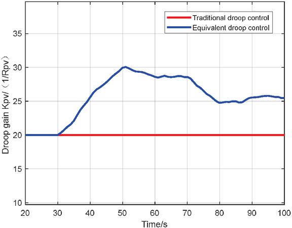
Figure 15 Droop gain.
From Figure 13, it is evident that the system’s minimum frequency point is significantly higher when using the equivalent droop control method based on SSA-Elman compared to the system under the traditional droop control method. Additionally, the time taken to reach the lowest frequency point is shorter. The system under the equivalent droop control method achieves a minimum frequency value of 49.8413 Hz at 51.6924 seconds, with a steady-state value of approximately 49.9103 Hz. In contrast, the system under the traditional droop control method reaches a minimum frequency value of 49.8174 Hz at 51.8552 seconds, with a steady-state value of approximately 49.9026 Hz. Hence, the simulation experiment results validate the effectiveness of the proposed equivalent droop control method, significantly improving the quality of frequency regulation.
2.4 Methods for Integrating Energy Storage
The photovoltaic-energy storage system is an innovative energy generation system that comprises photovoltaic equipment and energy storage equipment. According to Figure 16, there are currently four distinct application scenarios for energy storage in photovoltaic systems, which depend on the specific installation location.
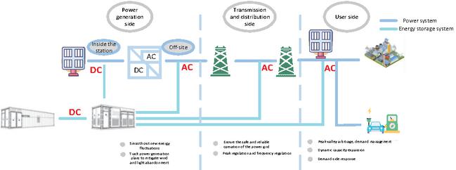
Figure 16 Application scenarios of energy storage in photovoltaic systems.
Table 2 Comparison of scenario applications
| Applicable Places or | Advantages or | Disadvantages or | |
| Application Form | Suitable Locations | Benefits | Drawbacks |
| Generation side (DC). | Severe limitations on the DC side, significant fluctuations in photovoltaic power, and no additional grid connection points. | Reducing the rate of wasted solar energy without the need for land approval processes and separate grid connection procedures. | Difficulties in operation and maintenance due to dispersed deployment, low profitability, and temporary inability to use DC-side energy storage as a photovoltaic dispatching and storage indicator. |
| Generation side (AC – within the station). | For larger-scale power plants, the primary considerations are cost and meeting grid connection requirements. | Promote the integration of new energy sources and enhance grid stability. | Low scheduling intention and low system utilization rate in the power grid. |
| Generation side (AC – outside the station). | For larger-scale power plants, the primary considerations are cost and meeting grid connection requirements. | A cost-effective system that meets the requirements of dispatching and storage. | No apparent drawbacks at the moment. |
| Grid side. | Large individual power plant scale, meeting grid dispatching requirements, with high requirements for system reliability and ease of operation and maintenance. | Participating in grid dispatching and engaging in electricity spot trading. | Unclear policies on the grid side, with no fixed revenue model. |
| User side. | Small-scale individual power plant with the main profit model being peak-valley arbitrage, featuring simple control logic. | Increasing dynamic expansion of photovoltaic power generation revenue, value arbitrage, providing ancillary services, and participating in corresponding demand markets. | Uncertainty in electricity pricing policies and a single revenue model. |
The integration of energy storage in photovoltaic power generation systems can be approached in four ways. The first approach involves utilizing the DC side of the system, where the generated DC electricity directly enters the energy storage system. The second approach utilizes the AC side of the photovoltaic power generation and can be implemented either within or outside the power plant. The third approach focuses on the grid side, with investment and construction led by the grid operator. Conversely, the fourth approach is implemented on the load side, with investment and construction carried out by industrial and commercial users. Table 2 provides a comprehensive comparison of these four application scenarios for energy storage systems. Based on the analysis presented in Table 2, locating the energy storage on the AC side outside the power plant offers multiple advantages. It meets grid connection requirements, ensures high control accuracy and reliability, has lower system costs, operates independently, exhibits a higher level of professionalism, offers diversified sources of income, and is well-suited for market development, without any apparent drawbacks.
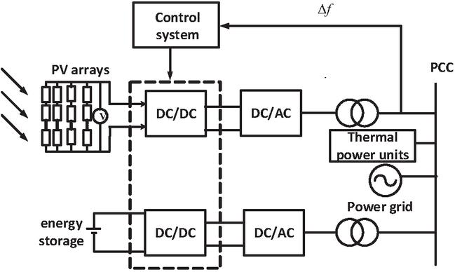
Figure 17 Topology of photovoltaic energy storage combined with frequency regulation system.
3 Photovoltaic-Energy Storage Combined Frequency Control System
3.1 Photovoltaic Energy Storage Combined Frequency Regulation System
The increasing emphasis on the availability of the photovoltaic-energy storage combined frequency control system stems from the substantial scale of individual energy storage power plants and the diverse revenue models they offer. This system meets the criteria for grid connection, ensuring high control accuracy and reliability. Moreover, it satisfies the requirements for distributed storage and scalable construction, while maintaining low system costs. Its ability to operate independently, its elevated level of professionalism, and its provision of diverse income sources make it suitable for market development. Furthermore, there are no apparent drawbacks when connecting energy storage to the AC side of power generation. Considering these factors, the system’s topology structure is outlined in Figure 17.
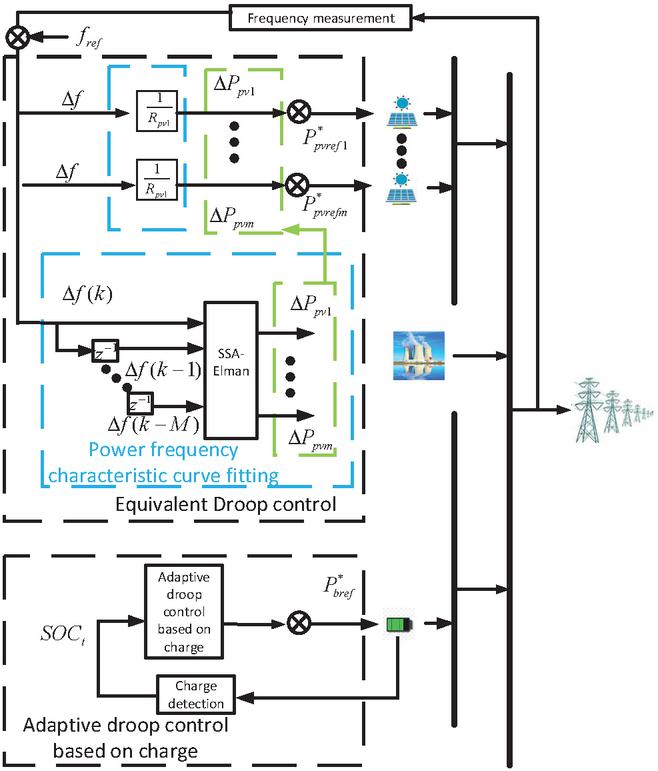
Figure 18 Improved control strategy.
The schematic diagram of the joint frequency modulation system for light storage is presented in Appendix B2. The energy storage system primarily comprises energy storage batteries, bidirectional DC/DC converters, grid-connected inverters, and their respective control systems. By adapting the control strategy of the bidirectional DC/DC converter, the energy can be adjusted in response to the fluctuations in grid frequency, thus achieving frequency modulation. Integrating energy storage devices into PV power plants can effectively smooth the PV output and enhance the overall frequency stability of the system [23]. Unlike conventional units, both PV and energy storage lack inertial response and the capability to perform primary frequency modulation. However, with the implementation of an additional frequency modulation control strategy, the distinction between these two components becomes less apparent [27].
The frequency modulation system actively contributes to research on frequency modulation strategies. This section presents an improved control strategy. Figure 1 illustrates a novel frequency modulation scheme that integrates load- shedding control. Instead of employing traditional droop control in the photovoltaic frequency modulation system, this study proposes an equivalent droop control based on SSA-Elman. This method enables real-time adjustment of the slope of the droop curve. By combining the control strategy from load shedding, it effectively mitigates frequency deviations caused by load step changes, variations in solar irradiance, and other weather factors. Moreover, a photovoltaic-energy storage joint frequency modulation system is constructed to compensate for the limitations of standalone photovoltaic frequency modulation, leveraging the flexible charging and discharging capabilities of the energy storage system. The energy storage-assisted photovoltaic power plant frequency modulation control strategy replaces traditional droop control with a charge feedback-based energy storage adaptive control strategy. This adaptive control strategy effectively tracks the charge status and frequency changes, while preventing overcharging and over-discharging of the energy storage. Additionally, the proposed auxiliary frequency modulation control and the adaptive droop control based on charge further enhance the frequency modulation potential of energy storage.
3.2 Frequency Modulation Strategy for Energy Storage Power Generation Participating in the Power Grid
Droop control is presently the most prevalent approach employed by energy storage batteries for participating in frequency modulation. The formula used to calculate the droop response is as follows:
| (15) |
In the equation: represents the deviation of the system frequency; represents the increment in power output for energy storage frequency regulation; represents the droop coefficient.
However, traditional droop control is prone to issues such as overcharging and over-discharging of the energy storage system. To extend battery usage time and improve frequency regulation flexibility and adaptability, this paper proposes a charge-adaptive droop control strategy that adjusts the grid frequency based on the battery charge. This approach effectively maintains the energy storage charge level and prevents a reduction in energy storage lifespan due to over-charging and over-discharging. The relationship between the output increment and the frequency deviation in charge-adaptive droop control is as follows:
| (16) | ||
| (17) |
In the provided equation, represents the virtual droop coefficient, represents the virtual droop charging coefficient, and represents the virtual droop discharging coefficient.
To avoid the complexities associated with the usage of piecewise functions, this research proposes the adoption of an adaptive construction method for the droop coefficient, implemented through the utilization of an S-shaped function [29]. The expression for the virtual droop charging and discharging coefficients can be derived from the following equation:
| (18) | ||
| (19) |
In the equation, represents the maximum value for the virtual droop coefficient. The values , , , represent the minimum, lower, higher, and maximum values, respectively, of the energy storage State of Charge (SOC). The adaptive coefficient n determines the trend of the curve, with a fixed value of 15 based on the results of simulation experiments conducted for this study.
This research aims to enhance the adaptive droop control based on battery charge by incorporating the concept of auxiliary frequency regulation control as proposed in reference [29]. The goal of this control design is to facilitate high-power charging and discharging of the energy storage system, particularly when the SOC is at a low or high level. By doing so, it enables a faster restoration to the ideal state and improves the subsequent frequency regulation capability during both energy storage charging and discharging. The following equation represents the expression for the auxiliary frequency regulation charging and discharging coefficient:
| (20) | ||
| (21) |
In the equation, represents the auxiliary frequency modulation control charging coefficient while represents the discharge coefficient. The parameter is used to adjust the magnitude of the curves for and . In this study, through simulation experiments, the values of and are set to 0.3 and 0.7, respectively.
The relationship between the comprehensive output of the energy storage frequency regulation stage is represented by Equation (23).
| (22) | |
| (23) |
In the equation, the energy storage frequency modulation coefficient is represented by , the energy storage frequency modulation charging coefficient is represented by , and the energy storage frequency modulation discharging coefficient is represented by . The relationship between these coefficients is established as depicted in the following equation.
| (24) | ||
| (25) |
3.3 Simulation Experiment
To validate the correctness and effectiveness of the optimization strategies proposed in this section, simulation studies will be conducted on the disturbances of solar irradiance at the source side and load fluctuation in the photovoltaic-thermal energy storage system, respectively. A simulation model of the photovoltaic-thermal energy storage system, as depicted in Figure 19, is constructed using the MATLAB/Simulink simulation platform. G1 denotes a 200 MW photovoltaic power station, G2 represents a 600 MW thermal power generator, and G3 indicates a 100 MWh/100 MW energy storage system. During the simulation of the source-side and load-side disturbances, the power and frequency are set to their rated values. The simulation parameters of the system can be found in Table 3.
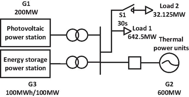
Figure 19 Simulation model of optoelectronic energy storage coupling system.
Table 3 Experimental parameters of the optical coupling system
| Parameters | Numerical Value |
| Rated capacity of a single energy storage power station. | 100 MWh/100 MW |
| Number of energy storage systems in the experiment. | 1 |
| The maximum output power of a single photovoltaic power plant. | 200 MW |
| Number of photovoltaic power plants in the experiment. | 1 |
| The output power of thermal power generator units. | 600 MW |
| Simulation period. | 1e–4s |
Case 1
In the optoelectronic coupling system, the initial load is 642.5 MW, and at 30 seconds, the load undergoes a sudden increase of 60 MW.
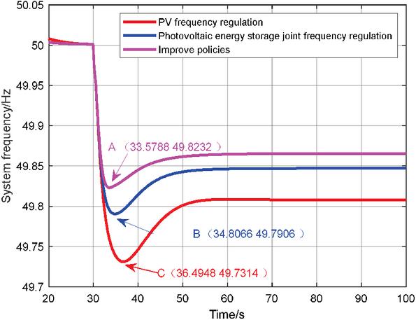
Figure 20 System frequency.
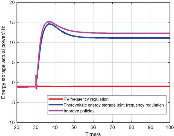
Figure 21 Actual output power of the energy storage.
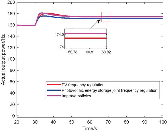
Figure 22 Actual output power of the photovoltaic power plant.
From the results presented in Figure 20, it is evident that the implementation of single photovoltaic frequency modulation leads to a steady-state frequency value of 49.7314 Hz, with a time of 36.4948 s required to reach the lowest frequency point. However, when energy storage is integrated and the combined photovoltaic-energy storage frequency modulation is adopted, the steady-state frequency value increases to 49.7906 Hz, and the time to reach the lowest frequency point decreases to 34.8066 s. Moreover, by employing the proposed improved strategy in this study, the steady-state frequency value further improves to 49.8232 Hz, with the lowest frequency point achieved in just 33.5788 s. These simulation experiment results serve as compelling evidence of the effectiveness of the proposed improved frequency modulation strategy, which demonstrates significant enhancements in the quality of frequency regulation.
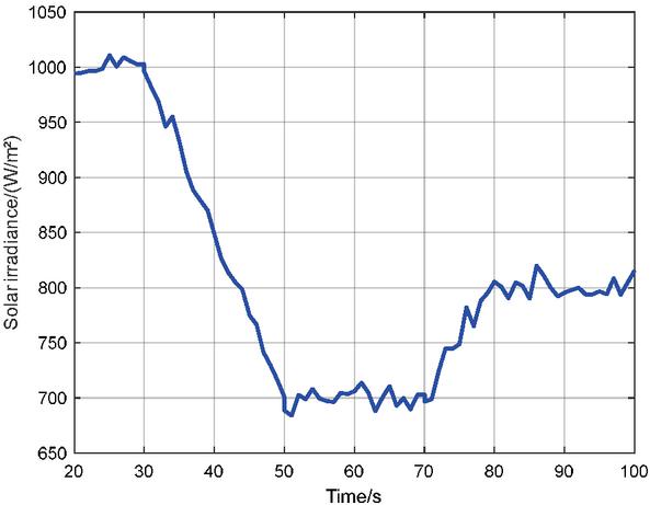
Figure 23 Solar irradiance.
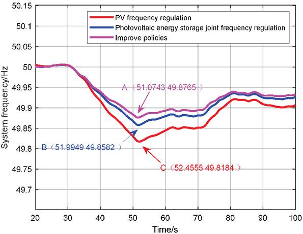
Figure 24 System frequency.
Case 2
The solar irradiance is depicted in Figure 23. Figure 25 illustrates the system frequency response of a photovoltaic system subject to irradiance disturbances, considering various control strategies. Figure 25 presents the actual power output of energy storage under irradiance disturbances while considering various strategies. Figure 26 presents the actual power output of photovoltaic power plant under irradiance disturbances while considering various strategies.
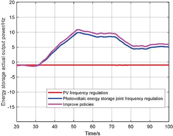
Figure 25 Actual output power of the energy storage.
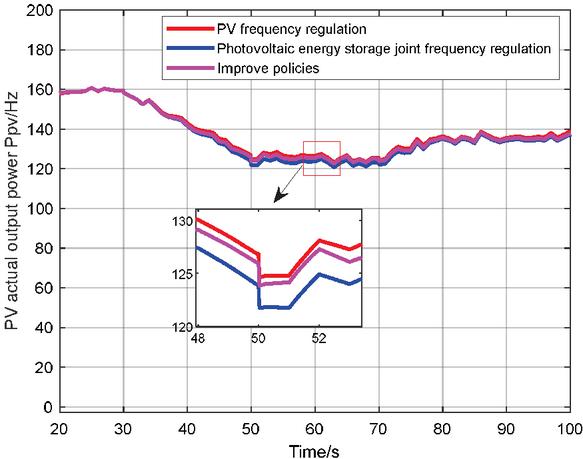
Figure 26 Actual output power of the photovoltaic power plant.
Figure 24 illustrates that the implementation of the proposed improved strategy results in a significantly higher lowest frequency point compared to the other two control methods in the system. Additionally, the time required to reach the lowest frequency point is shorter. The proposed method achieves a minimum frequency value of 49.8765 Hz, reached in 51.0743 seconds, with a steady-state value of approximately 49.9297 Hz. In contrast, the single photovoltaic frequency modulation system reaches a minimum frequency value of 51.8184 Hz in 52.4555 seconds, with a steady-state value of approximately 49.9015 Hz. When energy storage is introduced, the system’s minimum frequency value is 49.8582 Hz, reached in 51.9949 seconds, with a steady-state value of approximately 49.9223 Hz. Therefore, the simulation experiment results validate the effectiveness of the proposed improved method in significantly enhancing the quality of frequency regulation.
4 Conclusions
(1) The traditional droop control in photovoltaic frequency modulation systems is replaced with SSA-Elman-based equivalent droop control in this study to leverage the rapid frequency modulation capability of photovoltaics. This method allows for real-time adjustment of the droop curve slope, effectively addressing system frequency deviation caused by load variations and irradiance changes, especially when combined with load shedding control.
(2) To overcome the limitations of single photovoltaic frequency modulation, a combined photovoltaic-energy storage frequency modulation system is established in this study to compensate for the incomplete frequency modulation capability of photovoltaics alone. An adaptive control strategy is proposed to mitigate the potential issues of overcharging and over-discharging in the energy storage system by dynamically tracking the charge state and frequency variations. By combining the equivalent droop control of the photovoltaic system, the improved frequency modulation strategy presented in this study harnesses the frequency modulation potential of the combined photovoltaic-energy storage system and flexibly adapts to load power fluctuations in various scenarios.
References
[1] Niu, X. and Luo, X. 2023. Policies and Economic Efficiency for Distributed Photovoltaic and Energy Storage Industry. Distributed Generation & Alternative Energy Journal. 38, 04 (May 2023), 1197–1222.
[2] Akram U, Khalid M, Shafiq S. Optimal sizing of a wind/solar/battery hybrid grid-connected microgrid system. IET Renew Power Gener, 2017;12(1):72–80.
[3] Nanou S I, Papakonstantinou A G, Papathanassiou S A. A generic model of two-stage grid-connected PV systems with primary frequency response and inertia emulation[J]. Electric Power Systems Research, 2015, 127:186–196.
[4] Jia Y, Wu R. Voltage source grid-connected PV inverters based on MPPT and droop control[C]. 2016 IEEE 2nd Annual Southern Power Electronics Conference(SPEC), 2016:1–6.
[5] M. Zhang, Z. Du, N. Li, et al. Research on frequency droop control strategy during is landed operation of high-voltage microgrids [J]. Proceedings of the Chinese Society for Electrical Engineering, 2012, 32(25): 20–26. (in Chinese).
[6] Zhong C, Zhou Y, Yan D Y. Power reserve control with real-time iterative estimation for PV system participation in frequency regulation[J]. International Journal of Electrical Power & Energy Systems, 2021, 124.
[7] Akram U, Nadarajah M, Shah R, et al. A review on rapid responsive energy storage technologies for frequency regulation in modern power systems[J]. Renewable and Sustainable Energy Reviews, 2020, 120.
[8] Jha, R. and Khan, B. 2022. Impact of Fuel Cell System on Under Frequency Load Shedding Scheme Design. Distributed Generation & Alternative Energy Journal. 37, 05 (May 2022), 1329–1348.
[9] Jayalakshmi, N.S. and Gaonkar, D. 2015. An integrated Control Approach and Power Management of Stand-alone Hybrid Wind/PV/ Battery Power Generation System with Maximum Power Extraction Capability. Distributed Generation & Alternative Energy Journal. 30, 04 (Oct. 2015), 15–36.
[10] Salama H. S., Baker A., Magdy G., et al. Virtual Inertia Emulation Through Virtual Synchronous Generator Based Superconducting Magnetic Energy Storage in Modern Power Systems[J]. Journal of Energy Storage, 2021, 44:103466.
[11] Mahmoud M. Mohamed, et al. Optimal virtual synchronous generator control of battery/supercapacitor hybrid energy storage system for frequency response enhancement of photovoltaic/diesel microgrid[J]. Journal of Energy Storage, Volume 51, 2022, 104317, ISSN 2352-152X.
[12] P.H.A. Barra, W.C. de Carvalho, T.S. Menezes, R.A.S. Fernandes, D.V. Coury, A review on wind power smoothing using high-power energy storage systems[J]. Renewable and Sustainable Energy Reviews, Volume 137, 2021, 110455, ISSN 1364-0321.
[13] Sridevi, H.R., Jagwani, S., Kulkarni, S.V., and Ravikumar, H.M. (2023). Frequency Control in an Autonomous Microgrid Using GA Based Optimization Technique. Distributed Generation & Alternative Energy Journal, 38(02), 595–610.
[14] M. Ahmadi Kamarposhti, H. Shokouhandeh, M. Alipur, I. Colak, H. Zare, and K. Eguchi, “Optimal designing of the fuzzy-PID controller in the load-frequency control loop of hydro-thermal power system connected to the wind farm by HVDC lines,” IEEE Access, vol. 10, pp. 63812–63822, 2022.
[15] Li Y, He L, Liu F, et al. Flexible voltage control strategy considering distributed energy storages for DC distribution network[J]. IEEE Transactions on Smart Grid, 2017(99): 1.
[16] J. Meng, J. Peng, Y. Wang, et al. Improved flexible virtual inertia control considering energy storage state of charge and frequency recovery characteristics [J]. Electric Power Automation Equipment, 2020, 40(6): 100–107. (in Chinese).
[17] X. Deng, W. Sun, W. Xiao. Comprehensive control method for energy storage battery participating in primary frequency regulation [J]. High Voltage Engineering, 2018, 44(4): 1157–1165. (in Chinese).
[18] Q. Li. Study on the participation of photovoltaic power generation in grid frequency regulation [D]. North China Electric Power University (Beijing), 2021. (in Chinese).
[19] P. Wu, B. Liu. Control and evaluation of photovoltaic primary frequency regulation considering weather and operating conditions [J]. Journal of Wuhan University (Engineering Edition), 2022, 55(3). (in Chinese).
[20] J. Jia, X. Yan. Rapid frequency regulation strategy for energy storage-assisted photovoltaic units based on improved RoCoF measurement method [J]. Transactions of China Electrotechnical Society, 2022, 37(1). (in Chinese).
[21] J. Wu, X. Yang, X. Zhai, et al. Analysis of primary frequency regulation characteristics of grid-connected photovoltaic power plants [J]. Electrical Measurement & Instrumentation, 2016, 53(19): 88–92. (in Chinese).
[22] Xiang Guobo. Optimal ITAE Control. Beijing: China Machine Press, 1986. Zhang J. H., Zhang B., Li Q., et al. Fast Frequency Regulation Method for Power System with Two-Stage Photovoltaic Plants[J]. IEEE Transactions on Sustainable Energy.
[23] Northeast Regulatory Bureau of National Energy Administration. Grid code for auxiliary service 11 management of grid-connected power plants in Northeast China, Shenyang (2019) (in Chinese).
[24] M. Hou, Y. Yuan, C. Yang, et al. Optimization of Elman residual self-correcting ground settlement prediction model based on sparrow search algorithm [J]. Science Technology and Engineering, 2023, 23(13): 5470–5480. (in Chinese).
[25] M. Wang, Y. Zheng, Z. Deng. Design of power load reliability prediction system based on BFA-Elman [J/OL]. Electronic Design Engineering: 1–5 [2023-07-20]. (in Chinese).
[26] Model of short-term electricity load forecasting based on Elman neural network model [J]. Electronic Design Engineering, 2022, 30(01): 121–126. DOI: 10.14022/j.issn1674-6236.2022.01.026.
[27] Peng Bo, Zhang Feng, Liang Jun. Collaborative control strategy for short-term frequency response of wind-storage system considering wind speed zoning [J]. Automation of Electric Power Systems, 2018, 42(8): 57–65.
[28] Z. Fu, J. Zhang, X. Cui, et al. Research on the optimization control strategy for energy storage supported photovoltaic participation in primary frequency regulation of the grid [J]. Renewable Energy Resources, 2021, 39(11): 1530–1540. DOI: 10.13941/j.cnki.21-1469/tk.2021.11.017. (in Chinese).
[29] G. Yan, M. Wang, S, Duan, et al. Energy storage primary frequency control strategy considering state-of-charge recovery [J]. Automation of Electric Power Systems, 2022, 46(21): 52–61. (in Chinese).
Biography

Jiayun Zhou is currently pursuing a Master’s degree in the Control Science and Engineering program at North China Electric Power University. His research primarily centers around the optimization of rapid frequency control strategies for photovoltaic energy storage systems, power electronic modeling, grid integration of photovoltaic energy storage systems, and the utilization of energy storage technology for enhancing response speed and operational flexibility. The objective of his work is to address the safety and stability concerns in large-scale grid-connected power generation. Specifically, his focus areas include droop control, inertia control, EADRC control, fuzzy control applied to frequency regulation in photovoltaic energy storage systems, and the application of reinforcement learning algorithms.
Distributed Generation & Alternative Energy Journal, Vol. 39_2, 263–296.
doi: 10.13052/dgaej2156-3306.3923
© 2024 River Publishers