Design of Hybrid Power System for Hydrogen Fuel Cell and Electric Vehicle
Sisi Xie* and Fangfang Du
Huanghe Jiaotong University, Jiaozuo, China
E-mail: xss12111019@163.com
*Corresponding Author
Received 07 November 2024; Accepted 11 March 2025
Abstract
Hydrogen fuel electric vehicles are the mainstream direction of future automotive development, but the hybrid power system structure of hydrogen fuel electric vehicles is relatively complex, resulting in a shorter battery life and lower energy utilization efficiency in the vehicle’s hybrid power system. In response to this issue, an energy handling solution grounded on minimum equivalent hydrogen consumption is studied and designed to optimize the energy management structure of hybrid power systems. At the same time, the study also proposes improved collaborative control to enhance the converter controller of the hybrid power system. The outcomes show that compared to traditional energy control strategies, the energy handling solution raised in the research can reduce the state of charge fluctuation rate of lithium batteries by 95.07% and the state of charge fluctuation rate of advanced condensers by 0.28%. The energy control strategy designed in the research can decline the hydrogen consumption level of the hybrid power system by 2.29g. The inverter controller designed for research has a basic error of 0 when tracking the current of fuel cells and lithium batteries. The hybrid power system designed for electric vehicles can reduce the hydrogen consumption of electric vehicles, while improving the stability of power output and state of charge, which helps to extend the service life of electric vehicle batteries.
Keywords: Hybrid power, electric vehicles, fuel cell, energy management, dynamic system.
Introduction
The energy mode of hybrid vehicles is commonly made up of an old-style fuel engine and an electrical motor. The electric energy of traditional hybrid vehicles’ electric motors is generally provided by lithium batteries, etc., and the energy storage level is relatively low [1, 2]. Fuel cell (FC) can transform the energy from chemistry into electricity, and its working principle is similar to that of a battery. Unlike batteries, FCs are not disposable consumables and can continuously generate electricity by supplying fuel and oxidizer from the outside. The core of an FC is its electrolyte membrane, which allows hydrogen ions to pass through but not electrons, thus driving electrons to flow in the external circuit and generate current. FCs carry the features of high conversion efficiency, no noise, low emissions, and high energy density, which can improve the energy storage level of automobiles [3–5]. However, the load response speed of FCs is slow and the output power is low, so auxiliary energy must be used in practical use. This leads to the need to redesign the power system of hybrid vehicles after using FCs as the electric motor power supply device, so that the energy utilization efficiency of hybrid vehicles can be ensured. The power system of existing hybrid vehicles still faces problems of high cost and insufficient energy utilization in large-scale commercial applications [6]. Therefore, to improve the energy utilization efficiency of hydrogen FC hybrid vehicles and optimize the driving experience of hydrogen FC hybrid vehicles, on the basis of the State of Charge (SOC) of partitioned batteries, an Energy Management Strategy (EMS) with the lowest equivalent hydrogen consumption (HC) is designed to optimize the hydrogen FC hybrid power system (HPS).
The innovation of the research lies in proposing an EMS based on HC. The EMS designed for research introduces the concept of SOC, dividing the battery SOC into different working intervals and setting a penalty function for each working interval to achieve precise control of the battery charging and discharging process. The study also introduced a fixed time convergent disturbance observer in HPS and optimized the control strategy of HPS based on collaborative control algorithm.
This paper will be divided into four parts: firstly, a review of the research progress on hybrid electric vehicle power systems at home and abroad, and secondly, the methods and materials section. This section is divided into three subsections. The first subsection is the construction of the electric power model for hybrid electric vehicles. The second subsection is the design of the hydrogen consumption minimization control strategy for hybrid electric vehicles. The third subsection is the design of the transformer control strategy for hybrid power systems. The third part of the article is a simulation experiment analysis of the research design content, and the last part is a summary of the research content and future prospects.
1 Related Works
Hybrid EV is the main research direction for future automotive development, as they use multiple energy sources as their power source. Wang et al. proposed an EMS grounded on best system operating losses to reduce the operating costs of EV and address the technological barriers of FCs. This strategy comprehensively considered factors such as power source durability. The outcomes showed that contrasted with existing methods, the operating cost of this method was significantly reduced, by 19.69% and 28.18%, respectively [7]. Sun et al. raised an adaptive deep reinforcement learning EMS based on driver detection to improve the energy efficiency and lifespan of FC vehicles. This strategy adopted hierarchical power allocation and driving behavior recognition. The outcomes showed that compared to the benchmark method, the new strategy largely declined HC and usage costs, and improved energy efficiency and economy [8]. Bendjedia et al. proposed a new online EMS to rise the performance of hybrid energy in EV. This strategy optimized HC and hybrid storage system lifespan. Compared with traditional strategies, the new strategy performed better within 700 kilometers. Experimental verification showed that the new strategy improved HC and system lifespan, outperforming the frequency strategy [9]. Van Do T et al. proposed high-performance active switching inverters for hybrid vehicles aiming to simplify circuits, reduce size, and extend lifespan. The outcomes reflected that compared with traditional inverters, the new topology improved efficiency by 2.71% and reduces component size [10]. Hou S et al. proposed an EMS that combined offline optimization and online algorithms to improve the energy management of FC EV. Tests showed that this EMS was significantly energy-saving and could adapt to different vehicle configurations, with further performance improvement as battery capacity increases [11].
Singh proposed a hybrid power management strategy that combined adaptive neural fuzzy inference to optimize the fuel consumption of hybrid EV. This strategy used proton exchange membrane (PEM) FCs as the main energy source, supplemented by advanced condensers and battery packs. The results showed that artificial intelligence technology had significantly improved power management [12]. Arat et al. proposed a hybrid propulsion system based on polymer electrolyte membrane FCs for Cri Cri light aircraft in order to promote the development of electric aircraft. The outcomes reflected that the system operated effectively during all stages of flight, with a total HC of 0.75 kilograms, a reserve of 0.25 kilograms for emergency use, and a total energy consumption of 33 kWh [13]. Xu et al. established a transient FC battery HPS model to study the output performance and dynamic response of FC EV. This model integrated multiple sub models and considered heat and mass transfer processes. The results showed that optimizing energy management could significantly save energy and extend the service life of FCs, providing guidance for dynamic simulation and energy management of FC EV [14]. Sun et al. proposed a novel EMS based on game theory to improve the economy and durability of FCs. This strategy considered power flow allocation as a non cooperative game, balancing power preferences through Nash equilibrium. The results showed that compared with fuzzy control and power following method, the new strategy reduced HC by 7% and 4.57% respectively, and improved FC durability by 125% and 21.8% [15]. Bairabatina S et al. proposed a multi input DC-DC converter to optimize the performance of hybrid EV. This converter integrated FCs and solar panels, and regulated voltage and power flow through multiple switching frequencies. Through modeling, design, and verification, the converter exhibited high gain, high efficiency, and simplified design, and its superior performance had been experimentally verified [16].
In summary, in practical applications, hybrid vehicles use multiple energy sources to provide power for the power system, and the use of FCs effectively reduces the carbon emissions level of the vehicle and improves energy efficiency. Hydrogen FCs are widely used due to their pollution-free nature and high energy utilization efficiency. However, the energy output characteristics of hydrogen FCs in practical use are relatively soft, which can lead to uneven energy allocation during vehicle operation. Therefore, the study proposes improvements to the EMS and converter controller of HPS to optimize the HPS of EV. The technical route of the study is shown in Figure 1.
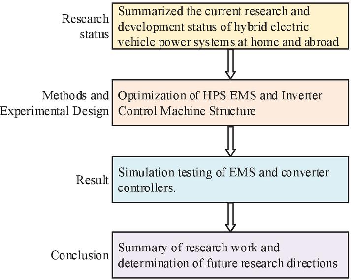
Figure 1 Study the technical route.
2 Methods and Materials
2.1 Construction of Power Model for Hydrogen FC EV
Hydrogen FCs are a common energy supply battery in HPS of EV. When hydrogen FCs are applied in EV, they need to be combined with auxiliary energy sources, including battery packs and advanced condensers [17, 18]. The hybrid system structure of EV mainly consists of an energy management system and a power drive system. The power drive system contains a converter and an electric motor, and the overall structure is shown in Figure 2.
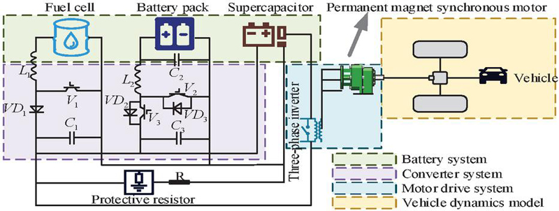
Figure 2 Overall structure of the hydrogen FC hybrid vehicle.
The power sources of hydrogen FC vehicles include FCs, lithium batteries, and advanced condensers. Hydrogen FCs are principally made up of bipolar plates, membrane electrode assemblies, and heat dissipation plates. The bipolar plate is responsible for connecting various single cells, providing channels for fuel and oxidant, guiding the flow direction of reaction gases, and ensuring that the reaction gases are evenly distributed throughout the electrodes [19, 20]. The membrane electrode assembly consists of a PEM, a catalytic layer, and a gas diffusion layer. PEMs act as membranes and electrolytes, while the catalytic layer contains catalysts that accelerate electrochemical reactions. The gas diffusion layer provides a pathway for gases to pass from the flow channel to the catalytic layer. The heat dissipation plate is mainly used for the heat dissipation of FCs. FCs have quite a lot modeling parameters, which makes it difficult to establish the model. The study adopts the hydrogen FC general electrical model for analysis and research, and its equivalent circuit diagram is represented in Figure 3.
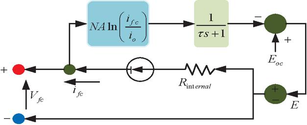
Figure 3 General electrical model equivalent circuit diagram of hydrogen FCs.
Lithium batteries are mainly used as auxiliary power sources for hydrogen FCs in HPS. The positive electrode of lithium batteries is usually composed of lithium compounds, such as lithium iron phosphate or lithium manganese oxide. The negative electrode is generally made of graphite or other carbon materials. Electrolytes can be liquid or solid, and their main function is to allow the passage of lithium ions while preventing direct electron transfer. Electrolytes typically contain lithium salts [21, 22]. A diaphragm is a thin film with a microporous structure located between the positive and negative electrodes, allowing lithium ions to pass through but preventing electron transfer and avoiding front touch between the positive and negative electrodes that could lead to a short circuit. The current collector is usually composed of metal foil, used to collect the current in the electrode material and export it out of the battery [23, 24]. The lithium battery model selected for the study is the lithium iron phosphate battery model. Advanced condensers are energy storage devices that work by rapidly storing and releasing charges on electrode surfaces, unlike batteries where energy is not stored through chemical reactions. Its structure is basically the same as that of a battery, and its energy storage mechanism is divided into electrostatic double-layer capacitors and Faraday capacitors. The equivalent circuit of lithium battery and supercapacitor is shown in Figure 4.
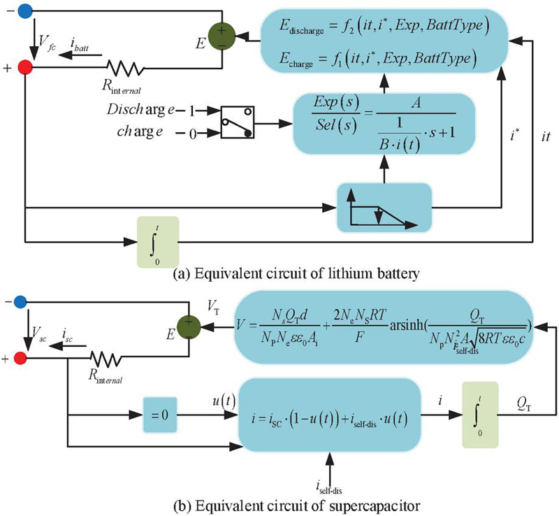
Figure 4 Lithium battery and supercapacitor equivalent circuit.
2.2 HPS HC Minimization EMS
EMS is one of the main structures of the hybrid power system in automobiles, mainly responsible for coordinating the allocation of output power among various energy supply systems. Hydrogen resources are the main consumption resources of hydrogen FCs. By reducing the consumption of hydrogen energy by the power system while ensuring the normal operation of the vehicle, the efficiency of hydrogen energy utilization can be risen, and the energy consumption and emissions of the vehicle can be reduced. Based on this objective, a hybrid energy management system objective function is constructed to reduce hydrogen fuel consumption, as shown in equation (2.2).
| (1) |
In Equation (2.2), , , and respectively represent the optimal output reference power of hydrogen FCs, lithium batteries, and advanced condensers. , , and respectively represent the equivalent HC of hydrogen FCs, lithium batteries, and advanced condensers. and represent the compensation coefficients. FCs, lithium batteries, and advanced condensers need to maintain power balance when doing work, as represented in Equation (2).
| (2) |
In Equation (2), represents the total load power. , , and respectively represent the output power of FCs, lithium batteries, and advanced condensers. The charging and discharging power of lithium batteries during use will affect their service life and vehicle safety. The output power and SOC of lithium batteries need to meet the constraints represented in Equation (3).
| (3) |
In Equation (3), represents the actual output power of the lithium battery. and represent the maximum and minimum output powers of lithium batteries, respectively. represents the actual SOC of the lithium battery. and respectively represent the maximum and minimum values of the SOC for lithium batteries. As the main energy supply device, the minimum output power of FCs cannot be zero, and the output power of FCs that is too high or too low will affect the service life of FCs. The basic constraint conditions of FCs are shown in Equation (4).
| (4) |
In Equation (4), and represent the maximum and minimum output powers of the FC. represents the actual output power of the FC. Advanced condensers need to assist vehicles in dealing with sudden power changes, ensuring that their SOC is within a safe and stable range. The constraint conditions for advanced condensers are shown in Equation (5).
| (5) |
In Equation (5), represents the actual output power of the supercapacitor. and represent the maximum and minimum output powers of advanced condensers. represents the actual SOC of the supercapacitor. and represent the maximum and minimum states of charge of the supercapacitor. All power output of hydrogen FCs comes from hydrogen, but the power output of lithium batteries and advanced condensers is independent of hydrogen. The energy released by lithium batteries and advanced condensers can be calculated through equivalent HC, and the HC of hydrogen FCs can be converted into energy output. The HC mass calculation of the power system is shown in Equation (6).
| (6) |
In Equation (6), represents the total HC of the power system. represents the HC of the FC. represents the HC of the lithium battery. represents the HC of the supercapacitor. The calculation of HC in FCs is shown in Equation (7).
| (7) |
In Equation (7), represents the actual power of the FC. , , and represent undetermined coefficients. represents the critical power. The calculation of equivalent HC of advanced condensers is shown in Equation (8).
| (8) |
In Equation (8), represents the terminal voltage of the supercapacitor. , , , and represent the equivalent resistance and efficiency of supercapacitor charging and discharging, respectively. represents the average output power of the FC. represents the charging and discharging power of the supercapacitor. The calculation of equivalent HC of lithium batteries is shown in Equation (9).
| (9) |
In Equation (9), and represent the charging and discharging productivity of advanced condensers. represents the open circuit voltage of lithium batteries. represents the charging and discharging power of lithium batteries. and represent the equivalent resistance of supercapacitor charging and discharging. When there is a power battery in the power system, its control needs an assured quantity of power to maintain. The study proposes using a penalty coefficient to replace the equivalent coefficient of the EMS objective function with the minimum equivalent HC, in order to control and adjust SOC. After adding equivalent coefficients, the objective function is shown in Equation (2.2).
| (10) |
In Equation (2.2), represents the penalty coefficient. When selecting the penalty function, the study only considers slow charging when the battery is sufficient and fast charging when the battery is insufficient. To further capture the battery of the power system, the study proposes to partition the battery into SOC zones to avoid rapid charging in prohibited or alert charging areas. The interval division of hybrid energy storage SOC is represented in Figure 5.
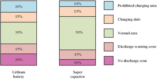
Figure 5 SOC partitioning diagram of lithium battery and supercapacitor energy storage.
Figure 5 shows that when the lithium battery power is between 35% and 65%, the battery is in the normal working area. When it is between 20% and 35%, 65% and 80%, it is the charging alert area. When it is above 80%, it is the prohibited charging area, and when it is below 20%, it is the prohibited discharging area. The threshold for the prohibited discharge zone of advanced condensers is 10%, the threshold for normal operation is 25% 75%, and the threshold for the prohibited charging zone is 90%. After introducing the partition penalty function, there is a threshold for selecting the penalty function, and the computing process of the penalty function is represented in Figure 6.
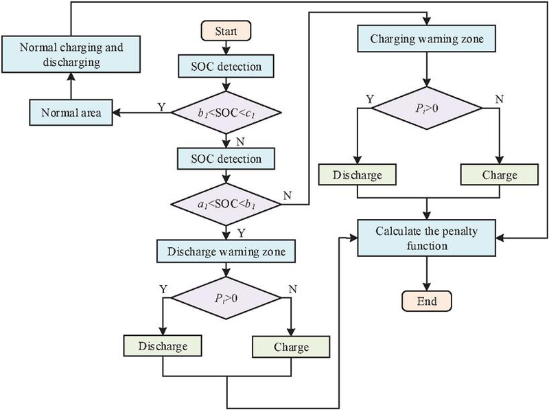
Figure 6 Partitioned SOC penalty function calculation process.
When calculating the penalty function, it is necessary to detect the SOC of the battery. If the SOC state of the battery maintains normalcy, it will be charged and discharged normally, and calculate the penalty function. If it is in the discharge warning zone and the output power is bigger than 0, it will discharge and calculate the penalty function; otherwise, it will charge and calculate the penalty function. If it is in the charging alert zone and Zeyu is in the discharging alert zone, the system will stop and the calculation process will end. The calculation of the lithium battery partition penalty function is shown in Equation (11).
| (11) |
In Equation (11), , , and represent the SOC thresholds for lithium battery partitioning. represents discharge penalty. represents charging penalty. represents the penalty function for lithium batteries. The calculation of the supercapacitor penalty function is shown in Equation (12).
| (12) |
2.3 Transformer Controller Based on Collaborative Control Algorithm
The converter is a crucial part in the automotive power system, apart from energy management. The HPS converter designed is a bidirectional converter [25, 26]. When designing a bidirectional converter for an HPS, it is necessary to consider the output characteristics of the FC to maximize the input voltage range of the converter. At the same time, in order to extend the service life and output voltage stability of FCs and lithium batteries, it is necessary to ensure a high conversion efficiency of the converter, while making the input current ripple range smaller and the output current ripple and output voltage ripple lower [27, 28]. The converter between the FC and the motor in the power system is a Boost converter, which is in charge of boosting the output current of the FC and directly supplying it to the motor. The calculation of its inductance and capacitance parameters is shown in Equation (13).
| (13) |
In Equation (13), represents the inductance parameter of the Boost converter. represents the capacitance parameter of the Boost converter. represents the high voltage side voltage. represents the low voltage side voltage. represents the switching cycle. represents the switching frequency. represents circuit power. represents the load resistance value. represents bus voltage ripple. The converter on the lithium battery side is a non-isolated bidirectional half bridge converter, which runs in both Buck and Boost modes. In Buck mode, the inductance and capacitance parameters of the converter are calculated using Equation (14).
| (14) |
In Equation (14), represents the capacitance parameter of the non-isolated bidirectional half bridge converter in Buck mode. means the inductance parameters of a non-isolated bidirectional half bridge converter in Buck mode. means the duty cycle of the switch tube. represents the capacitance value. In Boost mode, the inductance and capacitance parameters of the converter are calculated using Equation (15).
| (15) |
The collaborative control algorithm achieves asymptotic convergence and stable operation of the system state by determining the desired region of the system state variables, namely the control manifold. The collaborative control of the converter using this algorithm is studied, and its control structure is shown in Figure 7.
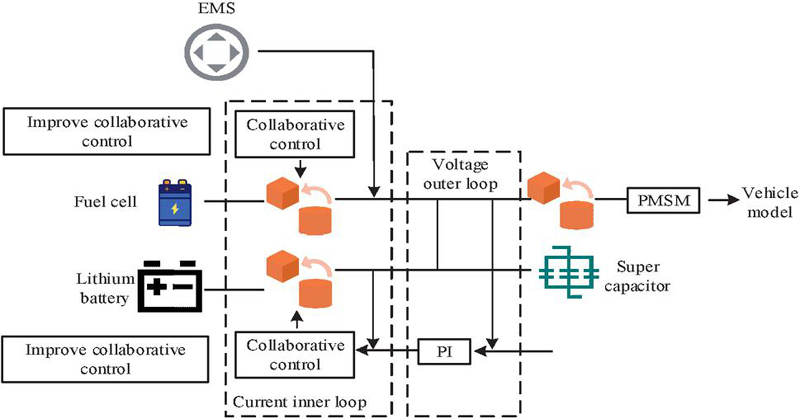
Figure 7 Schematic diagram of the converter control structure based on cooperative control.
The control structure of the designed converter system mainly controls the current inner loop. In order to further increase the tracking ability and anti-interference level of the controller, a disturbance observer that converges at a fixed time is introduced into the macro variables of the controller.
3 Results
3.1 EMS Simulation Experiment Analysis
To testify the validity of the EMS given in the study, a simulation testing environment was built and the EMS designed in the study was simulated and tested. The simulation testing environment built for the research was based on the MATLAB platform, and the simulation model was a complete vehicle model of a hydrogen FC hybrid EV. The primary structure of the model was the HPS, energy management system, and converter control structure. The power system parameters and vehicle model parameters are represented in Table 1.
The study analyzed the SOC convergence of lithium batteries and advanced condensers under three different control strategies: traditional PID control, Equivalent Consumption Minimization Strategy (ECMS), and partitioned ECMS (P-ECMS). The results are shown in Figure 8.
Table 1 Battery parameters and the complete vehicle model parameters
| Model | Name | Value | Model | Name | Value |
| Lithium cell | Rated capacity | 40 Ah | Super capacitor | Rated capacity | 156 F |
| Rated voltage | 50 V | Rated voltage | 390 V | ||
| Vehicle | Mass | 1025 kg | FC | Power rating | 85 kW |
| model | Wheel radius | 0.25 m | Maximum powe | 100 kW | |
| Front face area | 2.6 m | Vehicle model | Drag coefficient | 0.26 |
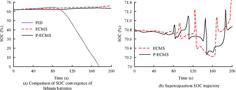
Figure 8 The SOC change of lithium battery and ultracapacitors under different control strategies.
Figure 8(a) shows the convergence of SOC in lithium batteries. Under the PID control strategy, the final SOC value was 0% and the SOC fluctuation rate was 100%. However, under the ECMS and P-ECMS control strategies, the final SOC values were 65.98% and 64.50%, respectively, and the SOC fluctuation rates were 6.42% and 4.03%, respectively. Figure 8(b) shows the SOC trajectory of advanced condensers under ECMS control strategy and P-ECMS strategy. Under the ECMS method, the final SOC value of the supercapacitor was 71.70%, and under the P-ECMS method, the final SOC value of the supercapacitor was 71.05%. Under the ECMS method, the SOC fluctuation rate of the supercapacitor was 1.20%, while under the P-ECMS method, the SOC fluctuation rate of the supercapacitor was 0.28%. The changes in HC of the power system under different control strategies are represented in Table 2.
Table 2 Effect of the control strategy on the HC in the power system
| HC (g) | |||
| Time (s) | PID | ECMS | P-ECMS |
| 20 | 1.52 | 1.48 | 1.44 |
| 40 | 1.73 | 1.72 | 1.69 |
| 60 | 2.26 | 2.28 | 2.25 |
| 80 | 4.06 | 3.02 | 2.32 |
| 100 | 4.23 | 3.74 | 3.02 |
| 120 | 4.32 | 4.33 | 4.01 |
| 140 | 5.74 | 5.75 | 4.82 |
| 160 | 8.52 | 7.52 | 5.92 |
| 180 | 9.12 | 8.54 | 6.83 |
3.2 Simulation Experiment Analysis of Converter Controller
When conducting simulation experiments on the converter controller, the experimental environment was consistent with the energy control strategy experimental environment. The study first analyzed the tracking control effects of traditional PID control, collaborative control, and improved collaborative control on the FC current. The outcomes are represented in Figure 9.
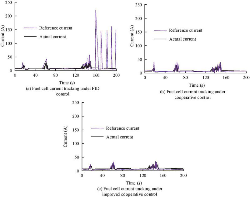
Figure 9 Effect of different converter controller structures on FC current tracking.
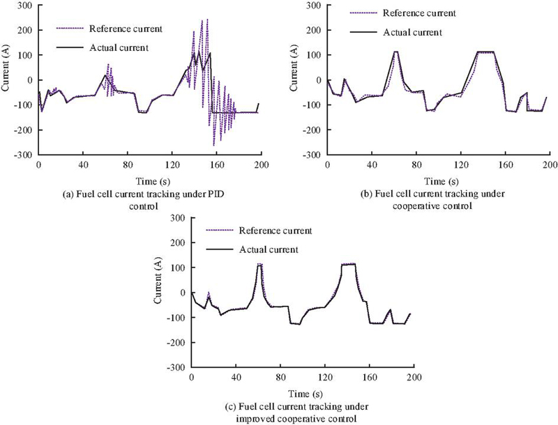
Figure 10 Effect of different converter controller structures on lithium cell current tracking.
Figure 9(a) shows the current tracking effect of FC under PID control. It is clear that the actual current deviated significantly from the reference current when the car accelerated or decelerated, especially after 160 seconds from the start of the simulation experiment, when the error could reach 200A. This indicates that the PID control strategy cannot effectively maintain accurate current tracking under dynamic conditions, which may lead to large system power fluctuations and thus reduce the system efficiency. Figure 9(b) shows the current tracking effect of FCs under collaborative control. It is obvious that after changing the basic control strategy, the error in the current tracking process of the converter was significantly reduced, but there was still a maximum error of 20A in the current tracking process. It shows that cooperative control has better performance than traditional PID control to reduce tracking error and improve the stability of the system. Figure 9(c) shows the current tracking effect of the FC under improved collaborative control. Under this control structure, the current tracking error was significantly reduced, with a maximum error of less than 10A. The improved collaborative control strategy can effectively achieve high-precision current tracking control and maintain good performance even under different operating conditions. The current tracking effect of three controller structures on lithium batteries is represented in Figure 10.
Figure 10(a) shows the current tracking effect of lithium battery under PID control. After 120 seconds, the current tracking error of this control structure began to increase, reaching a maximum of 150A. The remaining time errors were at a relatively low level. Figure 10(b) shows the current tracking effect of lithium batteries under collaborative control. It can be seen that under this control structure, the current tracking effect throughout the entire process was at a high level, and the error was always below 10A. Figure 10(c) shows the current tracking effect of lithium batteries under improved collaborative control. Under the control hole structure, the current tracking error of the lithium battery remained at 0 for a long experimental time. The current tracking error results of FCs and lithium batteries under different controller structures are shown in Figure 11.
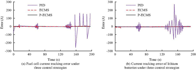
Figure 11 Signal graph of current tracking error between FC and lithium battery under different control strategies.
Figure 11(a) shows the FC current tracking error under three control structures. The three control structures had varying degrees of errors in tracking the current of the FC when the speed of the car changed. The first speed change was around 20 seconds, at which point the error between the improved collaborative control and the collaborative control was basically zero. However, in the following speed changes, the error of PID control gradually increased, with the highest error reaching 212A. Figure 11(b) shows the current tracking error of lithium batteries under three control structures. The overall error of the improved collaborative control was basically 0. When the collaborative control was around 60 s, the error slightly increased, about 8 A. Under the PID control strategy after 120 seconds, the error in tracking the current of the lithium battery significantly increased, reaching a maximum of 250 A. Moarref B et al. [26] proposed an energy management strategy based on mixed uncertainty, while Tang Z et al. [28] proposed an energy management strategy based on fuzzy logic control. The research design method utilizes SOC partitioning technology and a hybrid power system converter controller based on collaborative control algorithm. In order to further verify the feasibility and novelty of the research design method, a comparison was made between the design method proposed in this paper and the above two methods in practical applications to improve the energy utilization efficiency of hybrid electric vehicles. In practical verification, the study selected the four most widely held hybrid vehicles on the market and replaced the control strategies of their hybrid systems to eliminate the influence of other vehicle factors on the experimental results. The results are shown in Table 3.
Table 3 Comparison of energy utilization efficiency improvement effects of hybrid electric vehicles
| This Study | Mixed Uncertainty | Fuzzy Logic Control | ||||
| Energy | Energy | Energy | Energy | Energy | Energy | |
| Utilization | Recovery | Utilization | Recovery | Utilization | Recovery | |
| Sample | Rate (%) | Rate (%) | Rate (%) | Rate (%) | Rate (%) | Rate (%) |
| 1 | 87.6 | 6.4 | 75.6 | 3.2 | 78.1 | 2.6 |
| 2 | 88.4 | 5.4 | 77.4 | 2.1 | 79.3 | 3.6 |
| 3 | 86.9 | 6.3 | 78.4 | 2.6 | 78.8 | 3.8 |
| 4 | 89.6 | 5.9 | 79.2 | 3.5 | 79.6 | 2.9 |
As shown in Table 3, the research design method can increase the energy utilization rate of hybrid vehicles to over 85%, with a maximum of 89.6%, while also increasing the energy recovery rate to around 6%. In practical applications, the other two methods have a mediocre effect on improving the energy utilization efficiency of hybrid vehicles, only able to increase it to over 70%. In terms of energy utilization efficiency, the research design method is 10.47% higher than the method proposed by Moarref B et al. and 9.17% higher than the method proposed by Tang Z et al.
4 Conclusion
To optimize the power system structure of hydrogen fuel hybrid EV and reduce their energy consumption, research has been conducted on optimizing the HPS of hydrogen fuel EV. A minimum equivalent HC energy control strategy for power systems was constructed with the goal of reducing HC levels. At the same time, a penalty function for battery charging and discharging states was introduced to constrain battery energy scheduling, thereby optimizing the HPS EMS. At the same time, the study also proposed the use of interference detectors to improve the collaborative control structure of the converter and optimize the converter controller. The outcomes indicated that under the P-ECMS method designed in the study, the SOC fluctuation rate of lithium batteries could be reduced to 4.03%, and the SOC fluctuation rate of advanced condensers could be reduced to 0.28, while the SOC fluctuation rate of traditional energy control strategies for lithium batteries was 100%. The ECMS control strategy designed in the research could reduce the HC of the HPS to 6.83 g, while the HC level was 9.12g when using traditional EMS. The converter controller structure designed for research had a basic zero current tracking error for FCs and lithium batteries. The hydrogen fuel EV HPS designed for research can reduce vehicle hydrogen consumption to 6.83 and improve the energy utilization efficiency of hybrid vehicles to 89.6%. The research and design of a hydrogen fuel electric vehicle hybrid power system can significantly reduce the hydrogen consumption level of the vehicle and improve the stability of battery SOC. The hybrid power system structure designed for research effectively improves the energy utilization efficiency of electric vehicles and extends their battery life. However, the research did not improve and optimize the structure of the EV motor when designing the HPS structure. Future research will establish a motor control structure model for EV, optimize the motor control structure, and further improve the performance of hydrogen fuel EV.
References
[1] Parikh A, Shah M, Prajapati M. Fuelling the sustainable future: a comparative analysis between battery electrical vehicles (BEV) and fuel cell electrical vehicles (FCEV). Environmental Science and Pollution Research, 2023, 30(20): 57236–57252.
[2] Wu Z, Zhao Y, Zhang N. A Literature Survey of Green and Low-Carbon Economics Using Natural Experiment Approaches in Top Field Journal. Green and Low-Carbon Economy, 2023, 1(1): 2–14.
[3] Zhang L, Ning L, Yang X, Zeng S, Yuan T, Li G, et al. Half-Power Prediction and Its Application on the Energy Management Strategy for Fuel Cell City Bus. Automotive Innovation, 2023, 6(1): 131–142.
[4] Chen J, Li S, Yang K, Wei C, Tang X. Deep Reinforcement Learning-Based Integrated Control of Hybrid Electric Vehicles Driven by Lane-Level High-Definition Map. IEEE Transactions on Transportation Electrification, 2023, 10(1): 1642–1655.
[5] Xu D, Zheng C, Cui Y, Fu S, Kim N, Cha S W. Recent progress in learning algorithms applied in energy management of hybrid vehicles: A comprehensive review. International Journal of Precision Engineering and Manufacturing-Green Technology, 2023, 10(1): 245–267.
[6] Ahmad F, Iqbal A, Asharf I, Marzband M, Khan I. Placement and capacity of ev charging stations by considering uncertainties with energy management strategies. IEEE Transactions on Industry Applications, 2023, 59(3): 3865–3874.
[7] Wang T, Qiu Y, Xie S, Li Q, Chen W, Breaz E. Energy management strategy based on optimal system operation loss for a fuel cell hybrid electric vehicle. IEEE Transactions on Industrial Electronics, 2023, 71(3): 2650–2661.
[8] Sun H, Tao F, Fu Z, Gao A, Jiao L. Driving-behavior-aware optimal energy management strategy for multi-source fuel cell hybrid electric vehicles based on adaptive soft deep-reinforcement learning. IEEE Transactions on Intelligent Transportation Systems, 2023, 24(4): 4127–4146.
[9] Bendjedia B, Rizoug N, Boukhnifer M, Degaa L. Energy management strategies for a fuel-cell/battery hybrid power system. Proceedings of the Institution of Mechanical Engineers, Part I: Journal of Systems and Control Engineering, 2023, 237(4): 704–716.
[10] Van Do T, Kandidayeni M, Trovão J P F, Boulon L. Dual-Source High-Performance Active Switched Quasi-Z-Source Inverter for Fuel Cell Hybrid Vehicles. IEEE Transactions on Power Electronics, 2023, 38(10): 12497–12507.
[11] Hou S, Yin H, Pla B, Gao J, Chen H. Real-time energy management strategy of a fuel cell electric vehicle with global optimal learning. IEEE Transactions on Transportation Electrification, 2023, 9(4): 5085–5097.
[12] Singh P. Enhancing Performance of Hybrid Electric Vehicle using Optimized Energy Management Methodology. International Journal of Data Informatics and Intelligent Computing, 2023, 2(3): 1–10.
[13] Arat H T, Sürer M G, Gökpinar S, Aydin K. Conceptual design analysis for a lightweight aircraft with a fuel cell hybrid propulsion system. Energy Sources, Part A: Recovery, Utilization, and Environmental Effects, 2023, 45(1): 46–60.
[14] Xu Y, Yang Z, Jiao K, Hao D, Du Q. Development of a comprehensive transient fuel cell-battery hybrid system model and rule-based energy management strategy. International Journal of Green Energy, 2023, 20(8): 844–858.
[15] Sun Y, Xia C, Yin B, Gao H, Han J, Liu J. Energy management strategy for FCEV considering degradation of fuel cell. International Journal of Green Energy, 2023, 20(1): 28–39.
[16] Bairabathina S, Subramani B. Design, prototype validation, and reliability analysis of a multi-input DC/DC converter for grid-independent hybrid electric vehicles. International Journal of Circuit Theory and Applications, 2023, 51(5): 2375–2405.
[17] Kargar M, Zhang C, Song X. Integrated optimization of power management and vehicle motion control for autonomous hybrid electric vehicles. IEEE Transactions on Vehicular Technology, 2023, 72(9): 11147–11155.
[18] Quan R, Li Z, Liu P, Li Y, Chang, Y. Yan H. Minimum hydrogen consumption-based energy management strategy for hybrid fuel cell unmanned aerial vehicles using direction prediction optimal foraging algorithm. Fuel Cells, 2023, 23(2): 221–236.
[19] Peng J, Chen W, Fan Y, He H, Wei Z, Ma C. Ecological Driving Framework of Hybrid Electric Vehicle Based on Heterogeneous Multi-Agent Deep Reinforcement Learning. IEEE Transactions on Transportation Electrification, 2023, 10(1): 392–406.
[20] Safiullah S, Rahman A, Ahmad Lone S. Optimal control of electrical vehicle incorporated hybrid power system with second order fractional-active disturbance rejection controller. Optimal Control Applications and Methods, 2023, 44(2): 905–934.
[21] Indu K, Aswatha Kumar M. Electric vehicle control and driving safety systems: A review. IETE Journal of Research, 2023, 69(1): 482–498.
[22] Hamednia A, Murgovski N, Fredriksson J, Forsman J, Pourabdollah M, Larsson V. Optimal thermal management, charging, and eco-driving of battery electric vehicles. IEEE Transactions on Vehicular Technology, 2023, 72(6): 7265–7278.
[23] Guo J, Wang J, Xu Q, Wang B, Li K. Deep reinforcement learning-based hierarchical energy control strategy of a platoon of connected hybrid electric vehicles through cloud platform. IEEE Transactions on Transportation Electrification, 2023, 10(1): 305–315.
[24] Zhao N, Zhang F, Yang Y, Coskun S, Lin X, Hu X. Dynamic traffic prediction-based energy management of connected plug-in hybrid electric vehicles with long short-term state of charge planning. IEEE Transactions on Vehicular Technology, 2023, 72(5): 5833–5846.
[25] Wang Y, Liu H, Yu H, Wu F, Wheeler P, Zhou Q, et al. A misalignment-tolerant hybrid coupler for electric vehicle IPT charging systems. IEEE Transactions on Vehicular Technology, 2023, 72(10): 12845–12856.
[26] Moarref B, Abedi S M, Modaresi S M. Optimal scheduling of power system integrated with hydrogen vehicles and flexible resources: A hybrid uncertainty management method. International Journal of Hydrogen Energy, 2025, 100: 658–667.
[27] Jiang W, Tashakor N, Abkenar P P, et al. Optimizing PV-Battery Hybrid Systems: A Reconfigurable Approach With Module-Level Maximum-Power-Point Tracking and Load Sharing. IEEE Transactions on Power Electronics, 2025, 40(1): 2327–2341.
[28] Tang Z, Liu J, Liu Y, et al. Approximate Optimal Energy Management of Thermal-HESS System for MIMO Fuzzy Logic Controller Based AGC. IEEE Transactions on Sustainable Energy, 2025, 16(1): 641–653.
Biographies

Sisi Xie obtained her Bachelor’s degree in Physics from Shangqiu Normal University in 2008 and her Master’s degree in Condensed Matter Physics from Southwest Jiaotong University in 2012. Currently, she serves as an associate professor at the General Education College of Huanghe Jiaotong University. Her research interests include new energy batteries, hydrogen fuel cell technology, and related fields.

Fangfang Du obtained a Bachelor’s degree in Communication Engineering from Henan Normal University in 2012. She obtained a Master’s degree in Computer Technology from Jiangxi University of Science and Technology in 2016. Currently, she is a lecturer in the Department of Intelligent Engineering at Huanghe Jiaotong University. Her areas of interest are research on the Application of the Internet of Things, image processing and pattern recognition.
Distributed Generation & Alternative Energy Journal, Vol. 40_1, 141–164.
doi: 10.13052/dgaej2156-3306.4016
© 2025 River Publishers