Determining the Correct Electrical Resistance of Conductors in Power Systems Analysis
Massimo Mitolo
Irvine Valley College, Irvine, CA, USA
E-mail: mitolo@ieee.org
Received 18 August 2024; Accepted 30 November 2024
Abstract
The electrical resistance of a conductor varies with its material (e.g., copper or aluminum) and operating temperature.
This paper discusses the importance of determining conductor resistance at the appropriate temperature for voltage drop calculations, short-circuit current assessments, and ground-fault current evaluations in power system design. To normalize conductors based on their electrical characteristics, standards specify nominal cross-sectional areas uniquely associated with specific resistance values per unit length at 20C. These resistance values, considering the metal’s resistivity, can be reliably measured, eliminating the need for potentially unreliable physical measurements, especially in stranded wires.
The paper highlights the need for conservative approaches in voltage drop calculations by considering maximum operating temperatures of insulation materials and outlines the methodologies for accurately determining the resistance for maximum and minimum prospective short-circuit currents calculations. Additionally, it addresses the significance of proper ground-fault currents calculations to ensure speedy protective device operation, thereby enhancing system safety and reliability. The principles and standards herein discussed are applicable across various global power systems, underscoring the universal importance of standardized practices in electrical resistance calculations.
Keywords: Conductor resistance, electrical resistivity, ground-fault current, insulation material, maximum short-circuit current, minimum short-circuit current, nominal cross-sectional area, power system design, temperature coefficient, voltage drop.
1 Introduction
The electrical resistance of a conductor varies with its material (e.g., copper or aluminum) and operating temperature. To standardize conductors based on their electrical characteristics, [1] specifies nominal cross-sectional areas, which are uniquely associated with specific resistance values per unit length at 20C. These resistance values, accounting for the resistivity of the metal, can be reliably measured and eliminate the need for potentially unreliable physical measurements of wires (e.g., the diameter), especially when the wire is stranded. The nominal cross-sectional area, which is therefore not subject to direct measurement, is a rounded value representing the total sum of the theoretical areas of all individual strands that constitute the wire. This approach ensures that conductors from different manufacturers can be compared on a like-for-like basis in terms of their electrical performance.
The resistance of a wire of length l, cross-section S and resistivity is given by Equation (1).
| (1) |
The resistivities of Copper and Aluminum at 20C in units of mmmm are listed in Table 1 [2, 3].
Table 1 Resistivity of copper and aluminum at 20C in mmmm
| CU | AL | |
| 18.51 | 29.41 |
Reference [1] groups conductors into four classes, 1, 2, 5 and 6, listed in Table 2.
Table 2 Classification of conductors
| Class | Conductor |
| 1 | Solid |
| 2 | Stranded |
| 5 | Flexible |
| 6 | More flexible than class 5 |
Conductors in Classes 5 and 6 are primarily intended for use in flexible cables and cords but can also be used for fixed installations. Figure 1 provides the resistance values for various nominal cross-sectional areas of Class 2 copper conductors at 20C, measured in m/m [1].
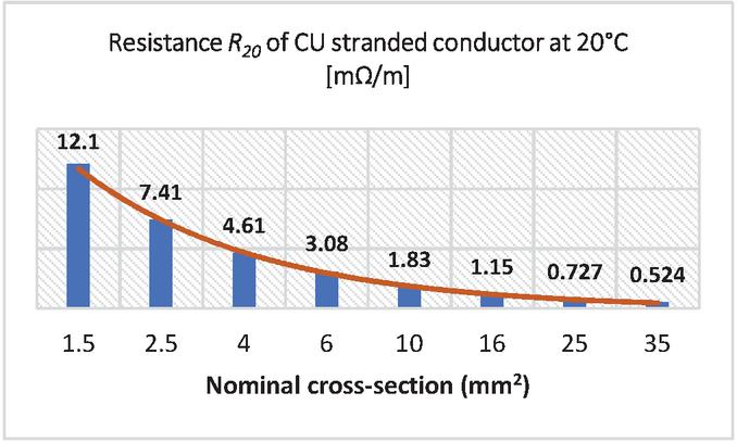
Figure 1 Resistance of CU stranded conductors at 20C [m/m].
It can be observed that the resistance decreases exponentially as the nominal cross-section increases. Skin and proximity effects, which influence the path of the a.c. current through the wire, increase the conductor’s resistance, but this increase is noticeable only for nominal cross-sections of 95 mm and above [2].
In the U.S., conductor sizes follow the American Wire Gauge (AWG) system and kcmil for larger sizes. Corresponding resistance values can be found in [4].
The resistance of a conductor varies with its temperature according to Equation (2) [5].
| (2) |
Here, 0.004 K is the temperature coefficient, which is sufficiently accurate for most practical purposes for conductors made of copper, aluminum, and aluminum alloy [3].
Determining the resistance of conductors in power systems is essential for calculating voltage drops, minimum and maximum short-circuit currents, and ground-fault currents. Selecting the appropriate conductor temperature for these calculations is, therefore, crucial.
2 Voltage Drop
In power systems, a voltage drop refers to the difference in voltage measured at a specific instant between two points in an electric circuit, caused by the electric current flowing through that circuit. Voltage drops are calculated using the design current , which is the electric current intended to be carried by an electric circuit during normal operation. The continuous current-carrying capacity , also referred to as ampacity, of the insulated conductor must be selected to meet or exceed the design current.
Reference [2] recommends considering the maximum operating temperature of the insulation material when evaluating conductor resistance for voltage drop calculations. This maximum operating temperature is 70C for thermoplastic insulation (e.g., PVC) and 90C for thermosetting insulation (e.g., EPR or XLPE). This conservative approach ensures that if is less than , the actual operating temperature and corresponding resistance will be lower than the maximum limits set by the insulation type.
Based on Equation (2), the resistance values in Figure 1 must be multiplied by temperature correction factors of 1.20 for thermoplastic insulation and 1.28 for thermosetting insulation to obtain the adjusted resistance for voltage drop calculations. A similar approach can be applied to voltage drops caused by inrush currents (e.g., motors starting), as their transient nature does not significantly affect the conductor’s temperature.
3 Maximum Prospective Short-Circuit Current
A short-circuit is an accidental or intentional connection between two or more conductive parts, forcing the electric potential differences between them to be equal to or close to zero. This results in an abnormal current flow, which must be interrupted by a protective device (i.e., circuit breaker or fuse). To determine the required breaking capacity of such a protective device, the maximum prospective short-circuit current in the electrical system must be calculated.
Typically, the maximum prospective short-circuit current is the symmetrical three-phase short-circuit current, denoted as [3], though this may not always be the case [6]. For determining the breaking capacity, it is generally unnecessary to calculate the phase-to-phase short-circuit current, , since it is always less than . The phase-to-neutral short-circuit current, , is used to determine the breaking capacity required for protective devices in single-phase circuits.
The worst-case scenario for determining the maximum short-circuit current occurs when conductors are at their minimum resistance, conventionally assumed to be at 20C. Thus, the resistance values in Figure 1 can be directly used for these calculations.
4 Minimum Prospective Short-Circuit Current
The minimum prospective short-circuit current is the current present at the end of the circuit downstream of a protective device. Calculating this value is essential to ensure that protective devices function correctly, even with low fault-current values. This is particularly important if no overload protective device is installed at the origin of the wiring system. Typically, this minimum prospective short-circuit current corresponds to the lowest phase-to-neutral short-circuit current value. .
For this calculation, [2] assumes that circuit breakers operate based on the instantaneous portion of their time-current characteristics during a short circuit.
In this assumption, the worst-case scenario is when conductors are carrying their full ampacity current and are at their maximum operating temperatures of 70C for PVC and 90C for EPR or XLPE. To determine the accurate conductor resistance, the resistance values from Figure 1 are adjusted by multiplying them with the temperature correction factors of 1.20 for wires with thermoplastic insulation and 1.28 for wires with thermosetting insulation. This results in the adjusted resistance .
5 Ground-fault Current
In low-voltage systems, the ground-fault current flows due to an unintended conductive path between the phase conductor and the protective conductor (PE), also known as the equipment grounding conductor [4]. This forms a ground-fault loop, a characteristic feature of TN systems [7] (Figure 2).
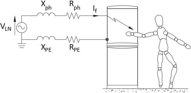
Figure 2 Ground-fault loop.
In TN systems, equipment and appliance enclosures are directly connected to the grounded point of the power source, such as the neutral point from a public power grid. This earthing method is used in several countries, including Australia, Canada, China, Germany, South Africa, Sweden, Switzerland, the U.K., and the U.S.
The ground-fault loop impedance includes the reactances X and X of the line conductor and the PE conductor, respectively. These reactances are temperature-independent and may be neglected for small cross-sectional areas. During ground faults, excessive fault-loop impedance may result in a fault current that is insufficient to activate the protective device promptly, thereby increasing the risk of electric shock for persons. To ensure electrical safety, the minimum ground-fault current must be calculated at the downstream end of circuits to verify that the disconnection of the supply occurs within the safe time [8].
5.1 PE and Line Conductor Routed Together
If the PE and line conductors are routed together in the same wireway, they will be at the same temperature, allowing their resistances R and R to be assessed at the maximum operating temperature of the insulation, similar to the calculation of adjusted resistance for the minimum prospective short-circuit current.
In the case of distribution circuits, which are circuits supplying one or more electric distribution panels, [2] requires that if a time-delayed circuit breaker is used as a protective device, the resistance for the PE conductor must be used. This resistance is calculated at the average temperatures given by Equations (3) and (4), corresponding to thermoplastic and thermosetting insulations, respectively.
| (3) | |
| (4) |
Here, 160 and 250 represent the maximum temperatures the conductor’s insulation can withstand, in degrees Celsius, for thermoplastic and thermosetting insulations, respectively. At the end of the ground-fault duration, the final conductor temperature cannot exceed these maximum values to prevent damages.
5.2 PE Separate From Line Conductor
If the PE conductor is separate from the line conductor, its temperature at the onset of the ground-fault can be assumed to be the conventional ambient temperature of 30C, since it does not normally carry any current. However, conservatively, [2] still assumes for the PE conductor’s temperature 70C for PVC and 90C for EPR or XLPE.
In the case of distribution circuits protected with fuses, [2] indicates that the resistance for the PE conductor must be used. This resistance is calculated at the average temperatures given by Equations (5) and (6), corresponding to thermoplastic and thermosetting insulations, respectively.
| (5) | |
| (6) |
Here, 30 represents the conventional ambient temperature in in degrees Celsius.
6 Summary of Temperature Correction Factors and Selection of Conductor Resistance
The temperature correction factors from 20C for calculations are summarized in Table 3.
Table 3 Temperature correction factors from 20C
| PVC | EPR or XLPE | |||
| (C) | Correction Factor | (C) | Correction Factor | |
| R | 20 | 1 | 20 | 1 |
| R | 70 | 1.20 | 90 | 1.28 |
| R | 115 | 1.38 | 170 | 1.60 |
| R | 95 | 1.30 | 140 | 1.48 |
The conductor resistances based on the desired calculations are summarized in Table 4.
Table 4 Selection of conductor resistance
| Calculation | Resistance |
| Voltage Drop | R |
| Max short-circuit current | R |
| Min short-circuit current | R |
| Ground-fault current(line to PE) | R |
| Ground-fault current(with time delayed circuit-breaker) | R |
| Ground-fault current(line to separate PE) | R |
| Ground-fault current(line to separate PE in distribution circuits with fuses) | R |
7 Conclusion
In this paper, I have discussed the crucial role of temperature considerations in ensuring accurate calculations for power systems. Determining the resistance of conductors at the proper temperature is essential for designing safe and reliable power systems. Utilizing the maximum temperature ratings of wire insulation for voltage drop calculations is a conservative approach, as actual operating temperatures are often lower, resulting in reduced resistance and improved system performance.
Calculating both maximum and minimum prospective short-circuit currents is vital for selecting appropriate protective device ratings. Using the nominal resistance values at 20C for maximum short-circuit currents in breaking capacity determination and adjusted resistance values for minimum short-circuit currents ensures circuit breakers and fuses operate correctly under various fault conditions, enhancing system safety.
Properly evaluating the ground-fault loop impedance is critical in TN systems to ensure prompt disconnection of supply in the event of a fault. This prevents potential electric shock hazards by maintaining adequate fault current levels to activate protective devices.
The temperature-dependent resistance of conductors is a fundamental aspect of power system design that should not be overlooked. It influences calculations and, therefore, the overall system reliability. By understanding and applying temperature correction factors, engineers can ensure that electrical systems operate safely and efficiently across a range of operating conditions.
References
[1] IEC 60228:2023, “Conductors of insulated cables.”
[2] CLC/TR 50480:2011, “Determination of cross-sectional area of conductors and selection of protective devices.”
[3] IEC 60909-0:2016, “Short-circuit currents in three-phase a.c. systems - Part 0: Calculation of currents.”
[4] NFPA 70:2023, “National Electrical Code.”
[5] M. Mitolo, H. Liu, F. Freschi, M. Tartaglia: “Ground-Fault Conditions in Low-Voltage Systems. Potential Differences between Exposed-Conductive-Parts”, IEEE Industry Applications Magazine; May/June 2014, Vol. 20, No. 3; pages 34–39.
[6] M. Mitolo: “Grounding the Neutral of Electrical Systems through Low Resistance Grounding Resistors: an application case”. IEEE Transactions on Industry Applications, Vol. 44, No. 5, September/October 2008, pages 1311–1316.
[7] M. Mitolo, H. Liu, J. Qiu: “Ground-Fault Loop Impedance Calculations in Single-Phase Systems”. IEEE Transactions on Industry Applications, Vol. 50, No. 2, March/April 2014; pages 1331–1337.
[8] IEC 60364-4-41:2005, “Low-voltage electrical installations – Part 4-41: Protection for safety – Protection against electric shock.”
Biography

Massimo Mitolo (Fellow, IEEE; Fellow, IET), a distinguished scholar and scientist, has been bestowed the Knighthood in the Order of Merit of the Italian Republic in acknowledgment of his exceptional contributions to scientific endeavors that have brought great honor to the nation. He is renowned for his remarkable achievements in the field of electrical engineering.
Sir Massimo earned his Ph.D. in Electrical Engineering from the University of Napoli “Federico II” in Italy. His unwavering dedication and significant impact on the field have led to his recognition as a Fellow of IEEE “for contributions to the electrical safety of low- voltage systems”. Furthermore, he holds the distinguished title of Fellow from the Institution of Engineering and Technology (IET) in the U.K. and is a member of the IEEE-HKN Honor Society. Additionally, he is a registered Professional Engineer in both the state of California and Italy.
Dr. Mitolo serves as a Full Professor of Electrical Engineering at Irvine Valley College in California. In addition to his academic responsibilities, he is a senior consultant specializing in the domains of failure analysis and electrical safety. His extensive research and industrial experience revolve around the comprehensive analysis and grounding of power systems, as well as electrical safety engineering.
Dr. Mitolo’s expertise is reflected in his publication record, encompassing over 180 journal papers, as well as the authorship of several influential books. Noteworthy titles authored by him include “Electrical Safety of Low-Voltage Systems” (McGraw-Hill, 2009), “Laboratory Manual for Introduction to Electronics: A Basic Approach” (Pearson, 2013), “Analysis of Grounding and Bonding Systems” (CRC Press, 2020), “Electrical Safety Engineering of Renewable Energy Systems” (IEEE Wiley, 2021), “Smart and Power Grid Systems: Design Challenges and Paradigms” (River Publishers 2022), and “Simulation-based Labs for Circuit analysis.” (River Publishers, 2024).
His scholarly endeavors have garnered significant recognition, culminating in his inclusion in the 2020, 2021 and 2022 World’s Top 2% Most-cited Scientists List, as compiled by Stanford University.
Within the Industrial and Commercial Power Systems Department of the IEEE Industry Applications Society (IAS), Dr. Mitolo actively engages in various committees and working groups, demonstrating his commitment to advancing the field and fostering collaborative efforts.
Acknowledging his achievements, Dr. Mitolo has been the recipient of numerous prestigious accolades throughout his career. Notably, he has been honored with the IEEE Region 6 Outstanding Engineer Award and has garnered nine Best Paper Awards for his exceptional scholarly contributions. Furthermore, he has received recognitions such as the IEEE Ralph H. Lee I&CPS Department Prize Award, the IEEE I&CPS Department Achievement Award, and the James E. Ballinger Engineer of the Year Award from the Orange County Engineering Council in California.
Distributed Generation & Alternative Energy Journal, Vol. 39_6, 1115–1124.
doi: 10.13052/dgaej2156-3306.3961
© 2025 River Publishers