Motor Control Algorithm Combining Model Predictive and Disturbance Compensator
Manman Li, Lianshuang Yu*, Yandong Chen and Jie Liu
School of Intelligent Equipment Engineering, Wuxi Taihu University, Wuxi, 214064, China
E-mail: LiansssYu@outlook.com
*Corresponding Author
Received 15 July 2025; Accepted 22 August 2025
Abstract
The accuracy of motor control systems is crucial for improving energy efficiency and production quality. However, traditional motor control methods suffer from slow response and weak anti-interference ability, which limits their performance in modern industrial applications. To optimize the dynamic performance of the motor control system, a motor control algorithm combining model predictive control and disturbance compensator is proposed. The composite control strategy based on model predictive and disturbance compensator had the shortest rise time and settling time in all speed stages. When the speed was 2,000 rpm, the rise time and settling time were 0.72 s and 1.89 s, respectively. Under different stages of friction torque disturbance in bearings, the steady-state error offset of the composite control strategy was minimized. When the rated torque was 20%, the steady-state error offset was 2.64%. The proposed motor control algorithm combining model predictive and disturbance compensator can effectively improve the accuracy and stability, providing effective technical solutions for motor control.
Keywords: MPC, current disturbance compensation, sliding mode compensator, motor control, dynamic response.
Introduction
The development and application of motors have promoted social progress, improved production efficiency, and enhanced quality of life [1]. Motor control, as a key technology in the field of automation, directly affects the operational efficiency, stability, and final product performance of motors. The accuracy of the motor control system is meaningful for achieving efficient energy utilization and optimizing the production process [2]. However, traditional motor control methods face slow response speed and insufficient anti-interference ability when facing complex dynamic environments and system parameter changes, making it hard to satisfy the needs of modern industry for real-time monitoring and precise control [3, 4]. For example, in the case of grid voltage sag, traditional Proportional-Integral (PI) control often results in significant speed fluctuations and even fails to recover in time; under sudden load variations, relying solely on MPC may cause excessive overshoot due to optimization delay, thereby affecting system stability; and in the presence of bearing friction torque disturbances or broadband noise environments, using the disturbance compensator alone often cannot completely eliminate steady-state deviations. These problems frequently occur in practical applications such as industrial motor drives, intelligent manufacturing equipment, and electric vehicles, which severely restrict the improvement of system performance.
Model Predictive Control (MPC), as an advanced control strategy, determines the optimal control input by solving a finite time optimization problem in each control cycle, thereby predicting and optimizing system behavior. MPC can effectively handle multivariable and constrained optimization problems, with advantages such as high control accuracy, fast dynamic response, and strong anti-interference ability [5, 6]. Disturbance compensation is a control method that adjusts based on the disturbance magnitude that causes changes in the adjusted parameter. When external interference just appears and can be detected, the regulator sends out an adjustment signal to make the adjustment amount change accordingly, and cancels out the interference before the deviation of the regulated amount occurs. Disturbance compensation is more timely and effective than feedback control [7]. While conducting feedback control, using external disturbance signals to directly control the output can quickly and effectively compensate for the impact of external disturbances on the entire system and improve control accuracy. To improve the accuracy and robustness of motor control, this study proposes a motor control algorithm that combines Model Predictive Control (MPC) with a Disturbance Compensator (DC). The method adopts a parallel-integrated structure, in which MPC is responsible for predictive optimization over future time steps and generating the optimal control input, while the disturbance compensator operates in parallel with MPC to estimate and compensate for external disturbances and parameter variations in real time. The compensation signal is directly superimposed on the MPC control output, thereby forming a composite control action. Unlike existing studies where MPC or the disturbance compensator is applied independently, the novelty of this work lies in the deep integration of predictive optimization and real-time disturbance compensation. This integration not only ensures fast dynamic response but also significantly reduces steady-state error and enhances system robustness under load variations and grid disturbances, thereby achieving high-precision motor control.
1 Related Works
MPC predicts the future behavior through dynamic models and optimizes control inputs to achieve goals. It is largely applied in industrial control, autonomous driving, and other fields [8, 9]. Harbi I et al. built a comprehensive control optimization strategy to address the high computational complexity and slow dynamic response in the predictive control of multi-level inverter models. This method reduced computational burden by improving weight factor design and optimizing the switch state search space. The proposed method reduced control delay by 42% in a three-level T-type inverter system and switch losses by 35% in a seven level cascaded H-bridge inverter [10]. Grandia R et al. built a perception method on the basis of nonlinear MPC to improve the stability and adaptability of quadruped robots in complex terrain. This method combined deep visual perception with real-time terrain mapping to enhance motion robustness by optimizing gait planning and contact force allocation. The results showed that the proposed method had a success rate of 97% in dynamic obstacle avoidance tasks and an energy efficiency improvement of 23% when walking on slopes [11]. Meduri A et al. built a two-layer optimization framework based on nonlinear MPC to address the lack of real-time and dynamic adaptability in robot full body motion planning in complex environments. This framework achieved efficient motion planning under multiple constraint conditions by combining task space trajectory optimization and joint space dynamic control. The proposed method improved computational efficiency by 40% in dynamic obstacle avoidance tasks for bipedal robots, while maintaining stable whole-body coordinated motion in unstructured terrain [12]. Salzmann T et al. proposed a real-time neural MPC framework based on deep learning to optimize the computational efficiency of agile robot platforms in dynamic environments. The proposed method reduced the computation time by 60% in quadcopter trajectory tracking tasks, and increased the control frequency to 100 Hz in high-speed obstacle avoidance scenarios, while maintaining tracking accuracy comparable to traditional MPC [13]. Feng L et al. proposed a cascaded MPC strategy to address the insufficient fault-tolerant control performance of six phase Permanent Magnet Synchronous Motors (PMSM) under fault conditions. This strategy achieved collaborative optimization control of current loop and speed loop by integrating dual loop predictive controller architecture and virtual vector modulation technology. The proposed method reduced torque ripple by 62% under single-phase open circuit faults and could still maintain 85% of rated torque output under two-phase faults [14].
Accurate motor control can maximize the electrical energy, reduce energy consumption, and improve equipment operating efficiency [15]. Liu Z et al. built an adaptive control method on the basis of B-spline wavelet neural network to optimize the control accuracy and anti-interference ability of linear motor drive systems under complex working conditions. This method combined a novel gradient descent algorithm with multi-resolution analysis techniques to accurately approximate the nonlinear dynamics of the system. The proposed method reduced the position tracking error of linear motors by 58% and shortened the recovery time by 65% under sudden load changes [16]. Govindharaj A et al. built an adaptive neural feedback control strategy to improve the stability control of permanent magnet DC motors driven by solar energy without batteries under light fluctuation conditions. The proposed control strategy reduced the speed recovery time by 73% under 80% sudden changes in lighting conditions, reduced torque fluctuations by 68% under dynamic load changes, and improved system energy conversion efficiency by 15% [17]. Deng H et al. built a fault-tolerant predictive control strategy that integrated deep reinforcement learning to solve the fault-tolerant control in electric vehicles driven by four-wheel hub motors under motor failure conditions. This method combined the MPC framework with reinforcement learning algorithms to achieve optimal torque allocation under fault conditions. The proposed control strategy reduced the lateral angular velocity tracking error by 52% in the case of single motor failure, and could still maintain 85% of the longitudinal driving force in dual motor failures [18]. Sun Q et al. proposed a quasi sine wave excitation strategy based on virtual current compensation to solve the large torque ripple and high noise caused by traditional square wave excitation schemes for switched reluctance motors. This method achieved smooth control of current waveform by constructing a virtual sine current reference model and a dynamic magnetic flux compensator. The proposed method reduced the noise level by 12 dB under rated speed conditions, while increasing the system efficiency by 8.5% [19]. Hiroe D et al. proposed a 10 MHz multi-sampling no beat control method based on a general intelligent power module controller for PMSM drive systems. The study improved the dynamic response performance by combining high-frequency multi sampling technology with deadbeat control strategy. The proposed method could suppress the delay effect in traditional control, increase the system response speed by about 40%, and reduce torque ripple by 25% [20].
In summary, reasonable motor control can reduce mechanical wear and electrical stress, and extend the service life of the motor. Many scholars have proposed many improved models to enhance the accuracy and efficiency of motor control. However, existing methods still have some limitations, such as insufficient adaptability to complex disturbance coupling and the need to optimize the balance between dynamic response and steady-state accuracy. Therefore, a motor control algorithm combining MPC and DC is built to optimize the dynamic performance and anti-interference ability, providing a new solution for high-precision motion control.
2 Motor Control Combining Model Predictive and Disturbance Compensator
2.1 Motor Control Algorithm Based on Model Predictive Control
As a key actuator in modern industry, the control performance of motors directly affects the overall efficiency and dynamic response. Although the traditional Proportional-Integral (PI) algorithm has been widely used in motor control, it relies on fixed parameter settings and is difficult to adapt to changes in system parameters and complex dynamic characteristics, resulting in limited control accuracy. When facing complex working conditions, there are problems such as slow dynamic response and weak anti-interference ability. MPC is a model-based closed-loop optimization control strategy that predicts the system behavior over a period of time in the future, optimizes control inputs, and strives to approach the target state as closely as possible while satisfying various constraints. The advantage of MPC lies in its ability to handle multivariable systems, constrained optimization problems, and strong robustness and adaptability [21, 22]. To optimize the performance of the motor control system, a motor control algorithm based on MPC is proposed. The MPC is to use the system’s state transition model to predict the system’s state in the future based on the current state and control inputs, and finally solve the control input sequence that minimizes the objective function through optimization algorithms [23]. The working process of MPC is shown in Figure 1.
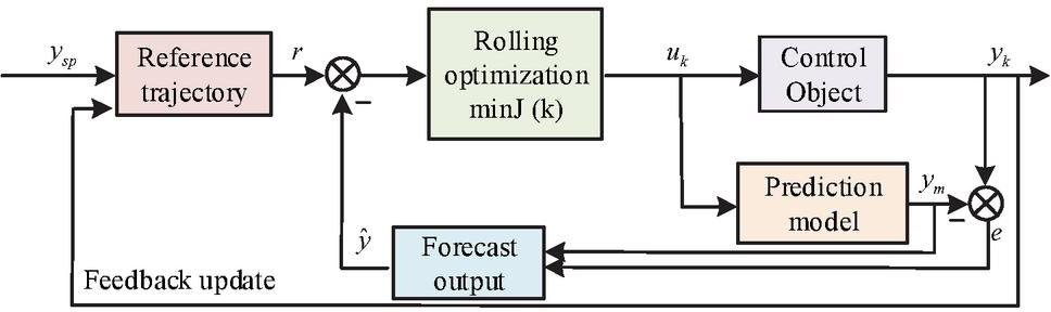
Figure 1 Working process of MPC.
In Figure 1, the workflow of MPC is as follows. First, the set output is compared with the reference trajectory . The errors generated by and are input into the rolling optimizer minJ(k) for processing. The rolling optimizer uses the MPC algorithm to predict the future behavior, generating a prediction output . The generated prediction output is then compared with to generate a prediction error . This error is used as a feedback signal for dynamic correction. Finally, the rolling optimizer calculates the optimal control input acting on the controlled object by minimizing the objective function. During this process, the actual output value and the model output are fed back in real-time to the prediction model for continuous updating of the predicted output , thus forming a closed-loop control system. This mechanism ensures that the system output can adaptively track the time-varying reference trajectory , while effectively suppressing the effects of model errors and external disturbances. The motor control system framework based on MPC is shown in Figure 2.
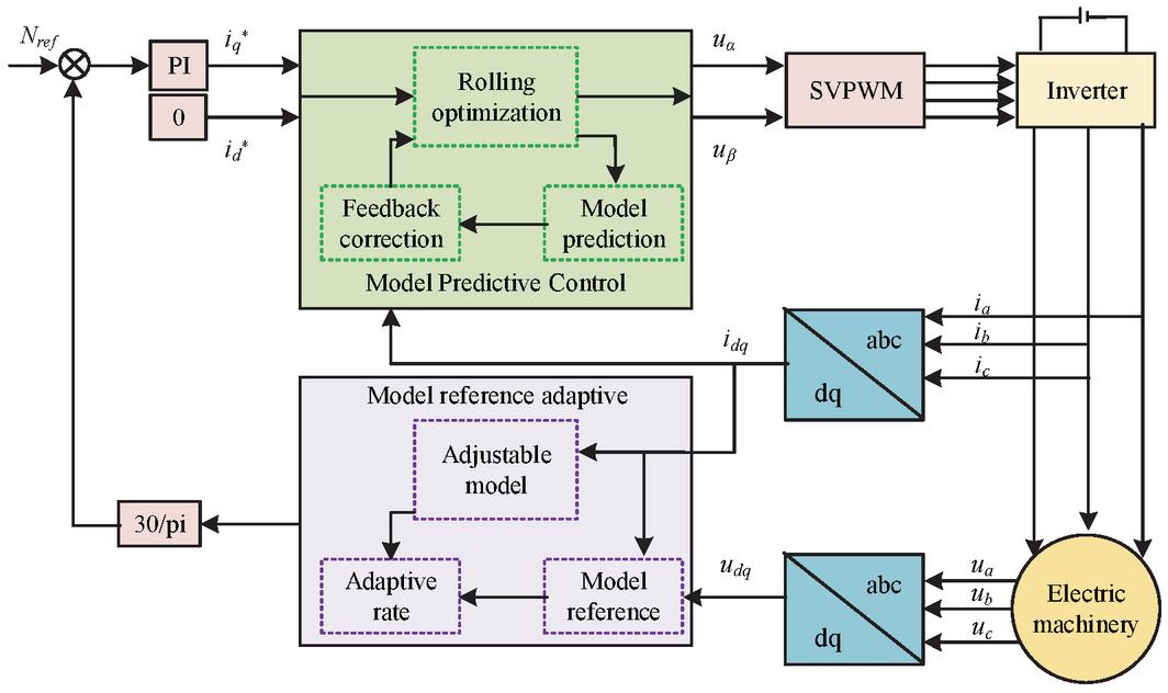
Figure 2 Motor control system framework based on MPC.
In Figure 2, the motor control system based on MPC adjusts the current through a PI controller to match the reference currents and . The model predictive controller utilizes rolling optimization, model predictive, and feedback correction to generate control voltages and . These voltages are converted into pulse width modulation signals of the inverter through a space vector pulse width modulation module, and then control the output voltages , and of the inverter to the motor. The currents , and speed are fed back to the system through sensors. The current is converted into the dq coordinate system through the abc/dq transformation, while the speed and torque information are processed through the 30/pi module and model reference adaptive system to adjust the adjustable model parameters and more accurately control the motor. For the motor control system, its dynamic characteristics can be described by a discrete-time state space model. The system state is shown in Equation (1).
| (1) |
In Equation (1), represents the system state, the subscript indicates the discrete-time step. signifies the control input. signifies the process noise. and represent the system matrix. The actual output value is calculated using Equation (2).
| (2) |
In Equation (2), represents the measurement noise. represents the output matrix. To make the actual output as close as possible to the expected reference trajectory, the optimization objective of MPC is defined. It minimizes the output error of future predictions and the weighted sum of control inputs by adjusting the control inputs during each control cycle. The definition of the optimization objective is shown in Equation (3).
| (3) |
In Equation (3), represents the system output at time step . signifies the reference trajectory at . signifies the weight matrix of the output error. represents the control input at time step . represents the weight matrix of the control input. represents the prediction range. The future state is predicted based on the current state and control input , as shown in Equation (4).
| (4) |
In Equation (4), represents the future state predicted at . Depending on the predicted state, the future output can be calculated, as shown in Equation (5).
| (5) |
In Equation (5), represents the future state predicted at . The optimization control input calculation is shown in Equation (6).
| (6) |
In Equation (6), represents the optimal control input obtained through MPC.
2.2 Composite Control Strategy Based on Disturbance Compensator
The motor control algorithm designed based on MPC can take full advantage of its ability to handle multivariable constraints and optimization problems. By predicting the system behavior and optimizing the control inputs, MPC achieves superior performance in terms of fast dynamic response, overshoot suppression, and effective constraint handling. However, in practical operating conditions, motor systems are inevitably subject to external disturbances (e.g., load fluctuations, grid disturbances) and internal uncertainties (e.g., parameter drift, modeling errors) [24]. These factors significantly affect the steady-state accuracy and long-term stability of the control system. Although MPC alone can maintain good dynamic performance, it is still insufficient for eliminating steady-state errors and ensuring robustness under such uncertain environments [25]. Therefore, this study further introduces a disturbance compensation mechanism on top of MPC. By designing a feedforward compensator with an appropriate transfer function, measurable disturbances can be fully compensated, thereby reducing or even eliminating steady-state errors. Integrating the disturbance compensator with MPC forms a composite control strategy that balances fast dynamic response and robust steady-state performance, ensuring that the motor system maintains high adaptability and control precision under complex and variable conditions.
The study aims to solve the system disturbance caused by changes in motor parameters by establishing a direct mapping relationship between current deviation and decoupling compensation. Figure 3 illustrates the structure of the current DC.
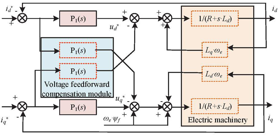
Figure 3 Structure of current disturbance compensator.
In Figure 3, the current DC structure of the motor adopts a voltage feedforward compensation strategy to improve the performance of the current loop. This structure consists of two main compensation modules, P and P, which decouple and compensate for d-axis and q-axis currents, respectively. P handles d-axis voltage feedforward, while P handles q-axis voltage feedforward. The compensator eliminates the speed coupling effect by introducing the term and transfer function, while using the link to achieve dynamic compensation of the current loop. The motor, as the controlled object, is located at the end of the system. Its input receives the control voltage after feedforward compensation, and its output feeds back the actual current value to form a closed-loop control. In response to the direct interference problem in the system, a sliding mode observer is constructed to estimate and compensate for the direct disturbance component caused by parameter changes in real time. The compensator constructed is shown in Figure 4.
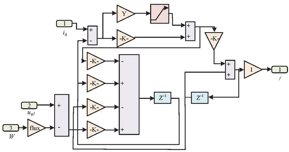
Figure 4 Structure diagram of sliding mode compensator.
As shown in Figure 4, the sliding mode compensator processes the input signals through several negative-gain blocks, and the outputs of these blocks are summed together and then passed through a unit delay block. The delayed signals are added to the original signals and further adjusted by a gain block and a saturation function, where the saturation function is used to limit the signal amplitude and prevent excessive control actions. Finally, the processed signals are fed through a positive feedback loop to enhance system stability. The disturbance estimates obtained by the sliding mode observer are adjusted by a compensation gain matrix and directly superimposed on the control voltage commands generated by the MPC, thereby forming feedforward compensation at the current loop level. Therefore, the designed disturbance compensator employs the sliding mode observation method to obtain disturbance estimates and injects the compensation signal into the dq-axis voltage control channel, achieving feedforward compensation in the current loop and effective suppression of unknown disturbances. The disturbance estimation value is shown in Equation (7).
| (7) |
In Equation (7), is the compensator gain matrix. signifies the estimated state. The disturbance compensation control input is shown in Equation (8).
| (8) |
In Equation (8), represents the compensated control input. Based on the current control input and state estimation, the state estimation value is updated. The updated state estimation is shown in Equation (9).
| (9) |
In Equation (9), represents the Kalman gain matrix. represents the updated state estimation. The disturbance estimation value is updated based on current state estimation and control inputs. The updated disturbance estimation value is shown in Equation (10).
| (10) |
In Equation (10), represents the updated disturbance estimation value. The future state is predicted based on the compensated control input. The future state is shown in Equation (11).
| (11) |
In Equation (11), represents the future state. The system output prediction is shown in Equation (12).
| (12) |
In Equation (12), signifies the system output prediction. The optimal control input calculation under the composite control strategy is shown in Equation (2.2).
| (13) |
In Equation (2.2), represents the optimal control input under the composite control strategy. The motor control system based on DC and MPC is shown in Figure 5.
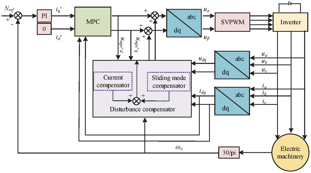
Figure 5 Motor control system based on disturbance compensator and model predictive control.
In Figure 5, the motor control based on DC and MPC first adjusts the current through a PI controller to make the actual current track the reference current . Secondly, the MPC module uses the deviation between the reference current and the actual current to generate the control voltage through model predictive and rolling optimization. After the abc/dq coordinate transformation, generates a pulse width modulation signal through a space vector pulse width modulation module, which drives the inverter to provide voltage to the motor. The DC provides real-time estimation and compensation for disturbances in the system. After being converted by a 30/pi module, the final speed is compared with the reference speed to further optimize the control strategy.
3 Analysis of the Effect of Motor Control
3.1 Experimental Environment and Parameter Settings
The experimental platform uses dSPACE MicroLabBox (DS1202) as the main control unit, equipped with Intel Core i7-1185G7 @3.0GHz CPU, 16GB of memory, and a real-time processor frequency of 2GHz. The power drive uses Infineon FS820R08A6P2B three-phase full bridge inverter, with a switching frequency set to 10kHz and a DC bus voltage of 300 V. The test motor is a PMSM with a rated power of 1.5 kW and a rated speed of 3,000 rpm. The selected software is MATLAB/Simulink R2023a. The detailed settings are shown in Table 1.
Table 1 Sample parameter settings
| The Parameter Name | Parameter Values | Describe | The Parameter Name | Parameter Values | Describe |
| Predicting Time Domain | 10 | Future state prediction steps | Compensation gain | 0.85 | Feedforward compensation coefficient |
| Control time domain | 5 | Optimize the number of input steps for control | Sliding mode gain | 1.2 | Robustness adjustment parameter for sliding mode observer |
| Weight matrix Q | Diag ([1, 0.5]) | Output error weights (current i, i) | Stator resistance R | 0.35 | dq-axis equivalent resistance |
| Weight matrix R | Diag ([0.1, 0.1]) | Control input weights (voltage ud, uq) | dq-axis inductance Ld, Lq | 2.5 mH, 3.2 mH | Inductance parameters |
| Observer bandwidth | 500 rad/s | Dynamic response bandwidth | Moment of inertia J | 0.0018 kgm | Total inertia of motor and load |
3.2 Dynamic Performance Analysis of Motor Control
Under different rotational speeds, the rise time and settling time of the motor controlled by the composite control strategy based on DC and MPC are compared with other methods. The comparison results are shown in Figure 6.
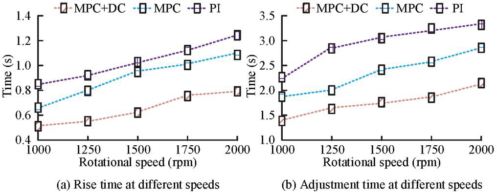
Figure 6 Comparison of rise time and settling time of motor control under different speed conditions.
In Figure 6(a), as the speed increased, the rise time of all control strategies also increased. The MPC+DC composite control strategy exhibited the shortest rise time at all speed stages, while traditional PI control had the longest rise time. When the speed was 2,000 rpm, the rise time of MPC+DC composite control and traditional PI control was 0.72 s and 1.22 s, respectively. In Figure 6(b), as the speed increased, the settling time of all control strategies also increased. The MPC+DC composite control exhibited superior performance. When the speed was 2,000 rpm, the settling time was 1.89 s. The MPC+DC composite control strategy has better adaptability and stability in handling speed step changes. Under different load conditions, the overshoot and torque pulsation rate of the motor controlled by the composite control strategy based on DC and MPC are compared with other methods, as presented in Table 2.
Table 2 Comparison of overshoot and torque pulsation rate of motor control under different load conditions
| Load | Control | Torque Pulsation | ||
| Conditions | Strategy | Overshoot (%) | Rate (%) | Peak Time (s) |
| 0% | PI | 7.5 | 3.2 | 0.60 |
| MPC | 2.8 | 1.1 | 0.40 | |
| MPC+DC | 1.9 | 0.6 | 0.32 | |
| 25% | PI | 9.1 | 4.5 | 0.75 |
| MPC | 3.5 | 1.5 | 0.52 | |
| MPC+DC | 2.3 | 0.8 | 0.42 | |
| 50% | PI | 11.0 | 5.8 | 0.90 |
| MPC | 4.2 | 1.8 | 0.65 | |
| MPC+DC | 2.7 | 1.0 | 0.52 | |
| 75% | PI | 13.2 | 7.1 | 1.05 |
| MPC | 5.1 | 2.2 | 0.76 | |
| MPC+DC | 3.1 | 1.3 | 0.62 | |
| 100% | PI | 15.6 | 8.5 | 1.20 |
| MPC | 6.5 | 2.9 | 0.85 | |
| MPC+DC | 3.9 | 1.7 | 0.70 |
According to Table 2, the MPC+DC composite control exhibited superior performance under various load conditions. However, the performance of traditional PI control was relatively poor when the load changed. When the load reaches 100%, the overshoot, peak time, and torque pulsation rate under traditional PI control are as high as 15.6%, 1.20 s, and 8.5%, respectively, whereas the MPC+DC strategy reduces them to 3.9%, 0.70 s, and 1.7%. This indicates that MPC+DC not only effectively suppresses overshoot and torque pulsation, but also shortens the peak time, resulting in faster dynamic response. The results effectively verify the stability and efficiency of the MPC+DC composite control in motor control tasks, especially its adaptability and control accuracy in load changes. The anti-interference recovery time and frequency bandwidth controlled by different control strategies for the motor are shown in Figure 7.
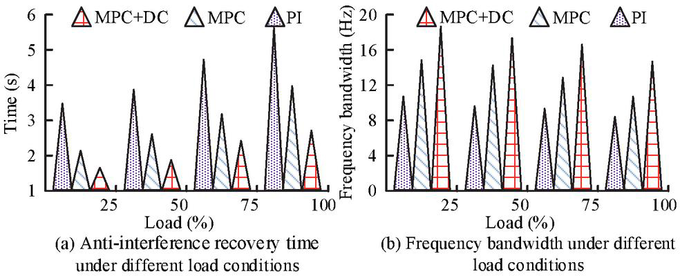
Figure 7 Comparison of anti-interference recovery time and frequency bandwidth of motor control under different load conditions.
In Figure 7(a), with the increase of load, the anti-interference recovery time of all control strategies increased. The traditional PI control had the longest anti-interference recovery time, while the MPC+DC composite control strategy had the shortest anti-interference recovery time. When the load was 100%, the anti-interference recovery time was 5.67 s and 2.77 s, respectively. As shown in Figure 7(b), with the increase of load, the bandwidth of all control strategies increased. When the load was 100%, the maximum bandwidth of the MPC+DC composite control strategy was 15.1 Hz.
3.3 Analysis of Anti-interference Ability of Motor Control
To verify the anti-interference ability, the speed drop amplitude and load sudden change recovery time are compared. The results are shown in Figure 8.
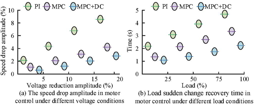
Figure 8 The speed drop amplitude and the load sudden change recovery time in motor control under different load conditions.
According to Figure 8(a), as the grid voltage decreased, the speed drop amplitude of all control strategies increased. The traditional PI control had the largest speed drop amplitude, while the MPC+DC composite control strategy had the smallest speed drop amplitude. When the voltage dropped by 20%, the speed dropped by 8.6% and 2.8%, respectively. From Figure 8(b), the load sudden change recovery time for motor control using MPC+DC composite control strategy was the shortest. When the load was 100%, the load sudden change recovery time was 2.09. The experimental results verify the effectiveness in dealing with voltage disturbances and load transients in the power grid. The steady-state error offset of different control strategies under different stages of bearing friction torque disturbance is shown in Table 3.
Table 3 Comparison of steady-state error offset under different rated torque conditions
| Load Conditions | Control Strategy | Overshoot (%) | Torque Pulsation Rate (%) |
| 0% | PI | 7.5 | 3.2 |
| MPC | 2.8 | 1.1 | |
| MPC+DC | 1.9 | 0.6 | |
| 25% | PI | 9.1 | 4.5 |
| MPC | 3.5 | 1.5 | |
| MPC+DC | 2.3 | 0.8 | |
| 50% | PI | 11.0 | 5.8 |
| MPC | 4.2 | 1.8 | |
| MPC+DC | 2.7 | 1.0 | |
| 75% | PI | 13.2 | 7.1 |
| MPC | 5.1 | 2.2 | |
| MPC+DC | 3.1 | 1.3 | |
| 100% | PI | 15.6 | 8.5 |
| MPC | 6.5 | 2.9 | |
| MPC+DC | 3.9 | 1.7 |
According to Table 3, as the rated torque increased, the steady-state error offset of all control strategies increased. The steady-state error offset of traditional PI control was the largest, while the steady-state error offset of MPC+DC composite control strategy was the smallest. When the rated torque was 20%, the steady-state error offsets were 11.64% and 2.64%, respectively. The proposed method has better adaptability and stability in bearing friction torque disturbance. The comparison results of disturbance suppression ratio and current tracking error of different control strategies under wideband white noise and sinusoidal torque disturbance are shown in Figure 9.
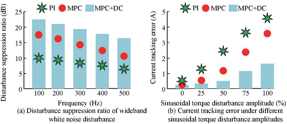
Figure 9 Disturbance suppression ratio and current tracking error of motor control under different disturbances.
In Figure 9(a), with the increase of wideband white noise frequency, the disturbance suppression ratio of all control strategies decreased. The disturbance suppression ratio of traditional PI control was the smallest, while the disturbance suppression ratio of MPC+DC composite control strategy was the largest. When the wideband white noise frequency was 500 Hz, the disturbance suppression ratios were 6.2 dB and 15.7 dB, respectively. In Figure 9(b), the MPC+DC composite control strategy had the smallest current tracking error under sinusoidal torque disturbance. When the amplitude of sinusoidal torque disturbance was 100%, the current tracking error was 1.51 A. The experimental results verify the effectiveness in dealing with wideband white noise and sinusoidal torque disturbance.
Finally, the study further verifies the advancement and robustness of the MPC+DC composite control strategy. Two comparison methods are selected: FOC+ADRC, which combines field-oriented control and active disturbance rejection control to adaptively compensate for external disturbances, and H+DOB, which combines H robust control with a disturbance observer, providing both theoretical robustness and strong disturbance suppression capability. At the same time, five operating scenarios S1 to S5 are set, including S1 rated condition with no disturbance and no parameter variation, S2 load disturbance with random 20% load fluctuation during operation, S3 parameter uncertainty with 15% variation in stator resistance and inductance, S4 measurement noise with white noise of 30 dB SNR added to current sampling, and S5 comprehensive complex condition with simultaneous presence of the uncertainties in S2 to S4. The comparison results are shown in Table 4.
Table 4 The comparison results of different methods under different working conditions
| Peak | Steady-state | Torque | |||
| Method | Scenario | Overshoot (%) | Time (s) | Error (%) | Ripple (%) |
| FOC+ADRC | S1 | 5.2 | 0.85 | 1.6 | 3.1 |
| S2 | 6.1 | 0.89 | 1.8 | 3.6 | |
| S3 | 6.6 | 0.92 | 1.9 | 3.9 | |
| S4 | 7.0 | 0.95 | 2.0 | 4.2 | |
| S5 | 7.4 | 0.97 | 2.1 | 4.5 | |
| H+DOB | S1 | 4.7 | 0.83 | 1.4 | 2.8 |
| S2 | 5.5 | 0.86 | 1.6 | 3.2 | |
| S3 | 6.0 | 0.89 | 1.7 | 3.5 | |
| S4 | 6.4 | 0.92 | 1.8 | 3.7 | |
| S5 | 6.8 | 0.95 | 1.9 | 3.9 | |
| MPC+DC | S1 | 3.9 | 0.72 | 0.4 | 1.8 |
| S2 | 4.2 | 0.75 | 0.5 | 2.0 | |
| S3 | 4.4 | 0.77 | 0.6 | 2.2 | |
| S4 | 4.6 | 0.79 | 0.7 | 2.3 | |
| S5 | 4.8 | 0.80 | 0.8 | 2.6 |
The results in Table 4 show that the proposed MPC+DC composite control strategy demonstrates clear advantages under all operating conditions. First, in terms of overshoot, MPC+DC consistently maintains the lowest level, about 2% to 3% lower than FOC+ADRC and 1% to 3% lower than H+DOB. Regarding peak time, MPC+DC achieves faster dynamic responses, generally about 0.1 to 0.2 seconds earlier, indicating superior dynamic performance. Second, for steady-state error, MPC+DC remains within 1% across all scenarios, significantly better than the other methods and ensuring high steady-state accuracy. In addition, for torque ripple, MPC+DC reduces fluctuations by approximately 30% to 40% compared with FOC+ADRC and by 20% to 30% compared with H+DOB, reflecting stronger stability. Particularly in the most complex S5 scenario, MPC+DC still maintains stable operation, with overshoot of only 4.8%, steady-state error within 1%, and torque ripple of 2.6%, which fully demonstrates its robustness and adaptability in handling load disturbances, parameter variations, and measurement noise.
4 Conclusion
The performance of motor control systems has a decisive impact on the fields of industrial automation and intelligent manufacturing, and its accuracy is directly related to energy utilization efficiency and production process optimization. To optimize the response speed and anti-interference ability, a motor control algorithm combining MPC and DC was proposed. Compared with other strategies, the MPCDC composite control strategy had the highest disturbance suppression ratio. When the wideband white noise frequency was 500 Hz, the disturbance suppression ratio was 15.7 dB. Under sinusoidal torque disturbance, the current tracking error of the MPC+DC composite control strategy was the smallest. When the amplitude of sinusoidal torque disturbance was 100%, the current tracking error was 1.51 A. Under different load conditions, the MPC+DC composite control significantly reduced overshoot and torque pulsation rate, which were 3.9% and 1.7%, respectively. The method effectively improves the motor control efficiency and reduces the control error. It should be noted that since MPC needs to solve optimization problems in real time during each control cycle, its computational complexity is relatively high. In the experiments, the average response time was extended by about 0.2–0.3 s under complex operating conditions, indicating a certain limitation in real-time performance. To address this issue, future work will consider introducing model reduction, fast optimization algorithms, or parallel computing hardware to reduce the computational burden and further shorten the system response time, as well as exploring coupling with lightweight control strategies to achieve a balance between high performance and real-time capability in engineering applications.
References
[1] Cheng M, Zhou J, Qian W. Advanced electrical motors and control strategies for high-quality servo systems-a comprehensive review. Chinese Journal of Electrical Engineering, 2024, 10(1): 63–85. DOI:10.23919/CJEE.2023.000048.
[2] Inan R. An Improved Model Predictive Current Control of BLDC Motor With a Novel Adaptive Extended Kalman Filter–Based Back EMF Estimator and a New Commutation Duration Approach for Electrical Vehicle. International Journal of Circuit Theory and Applications, 2025, 53(2): 1135–1150. DOI:https://doi.org/10.1002/cta.4407.
[3] Wellendorf A, Tichelmann P, Uhl J. Performance Analysis of a Dynamic Test Bench Based on a Linear Direct Drive. Archives of Advanced Engineering Science, 2023, 1(1):55–62. DOI:https://orcid.org/0000-0001-7711-6050.
[4] Liang J, Feng J, Fang Z. An energy-oriented torque-vector control framework for distributed drive electric vehicles. IEEE Transactions on Transportation Electrification, 2023, 9(3): 4014–4031. DOI:10.1109/TTE.2022.3231933.
[5] Ji Y, Ni L, Zhao C, Lei C, Du Y, Wang W. TriPField: A 3D potential field model and its applications to local path planning of autonomous vehicles. IEEE Transactions on Intelligent Transportation Systems, 2023, 24(3): 3541–3554. DOI:10.1109/TITS.2022.3231259.
[6] Abdelghany M B, Al-Durra A, Gao F. A coordinated optimal operation of a grid-connected wind-solar microgrid incorporating hybrid energy storage management systems. IEEE Transactions on Sustainable Energy, 2023, 15(1): 39–51. DOI:10.1109/TSTE.2023.3263540.
[7] Zhao L, Yang G, Li Y, et al. Fuzzy adaptive optimal backstepping control of the FO MEMS resonator under imprecise target trajectory with disturbance compensation mechanism. Nonlinear Dynamics, 2023, 111(19): 17939–17959. DOI:10.1007/s11071-023-08786-z.
[8] Narasingam A, Son S H, Kwon J S I. Data-driven feedback stabilisation of nonlinear systems: Koopman-based model predictive control. International Journal of Control, 2023, 96(3): 770–781. DOI:https://doi.org/10.1080/00207179.2021.2013541.
[9] Mao X, Li P, Weng Z, Zhao, J. Distributed tube model predictive control for string stability of heterogeneous vehicle platoons. Proceedings of the Institution of Mechanical Engineers, Part I: Journal of Systems and Control Engineering, 2023, 237(10): 1777–1788. DOI:10.1177/09596518231168175.
[10] Harbi I, Rodriguez J, Liegmann E, Makhamreh H, Heldwein M L, Novak M, Kennel R. Model-predictive control of multilevel inverters: Challenges, recent advances, and trends. IEEE Transactions on Power Electronics, 2023, 38(9): 10845–10868. DOI:10.1109/TPEL.2023.3288499.
[11] Grandia R, Jenelten F, Yang S, Yang S, Farshidian F. Hutter M. Perceptive locomotion through nonlinear model-predictive control. IEEE Transactions on Robotics, 2023, 39(5): 3402–3421. DOI:10.1109/TRO.2023.3275384.
[12] Meduri A, Shah P, Viereck J, Khadiv M, Havoutis I, Righetti L. Biconmp: A nonlinear model predictive control framework for whole body motion planning. IEEE Transactions on Robotics, 2023, 39(2): 905–922. DOI:10.1109/TRO.2022.3228390.
[13] Salzmann T, Kaufmann E, Arrizabalaga J. Real-time neural mpc: Deep learning model predictive control for quadrotors and agile robotic platforms. IEEE Robotics and Automation Letters, 2023, 8(4): 2397–2404. DOI:10.1109/LRA.2023.3246839.
[14] Feng L, Wang Z, Feng J, Song W. Cascaded model predictive control of six-phase permanent magnet synchronous motor with fault tolerant ability. CES Transactions on Electrical Machines and Systems, 2023, 7(3): 311–319. DOI:10.30941/CESTEMS.2023.00033.
[15] Li T, Sun X, Yao M, Guo D, Sun Y. Improved finite control set model predictive current control for permanent magnet synchronous motor with sliding mode observer. IEEE Transactions on Transportation Electrification, 2023, 10(1): 699–710. DOI:10.1109/TTE.2023.3293510.
[16] Liu Z, Gao H, Yu X, Lin W, Qiu J, Rodríguez-Andina J J, Qu D. B-spline wavelet neural-network-based adaptive control for linear-motor-driven systems via a novel gradient descent algorithm. IEEE Transactions on Industrial Electronics, 2023, 71(2): 1896–1905. DOI:10.1109/TIE.2023.3260318.
[17] Govindharaj A, Mariappan A, Aladiyan A, Alhelou H H. Real-time implementation of adaptive neural backstepping controller for battery-less solar-powered PMDC motor. IET Power Electronics, 2023, 16(1): 128–144. DOI:https://doi.org/10.1049/pel2.12369.
[18] Deng H, Zhao Y, Nguyen A T, Huang C. Fault-tolerant predictive control with deep-reinforcement-learning-based torque distribution for four in-wheel motor drive electric vehicles. IEEE/ASME Transactions on Mechatronics, 2023, 28(2): 668–680. DOI:10.1109/TMECH.2022.3233705.
[19] Sun Q, Lyu G, Liu X, et al. Virtual current compensation-based quasi-sinusoidal-wave excitation scheme for switched reluctance motor drives. IEEE Transactions on Industrial Electronics, 2023, 71(9): 10162–10172. DOI:10.1109/TIE.2023.3333056.
[20] Hiroe D, Zhang X, Nakamura K. A study of 10MHz multi-sampling deadbeat control for PMSM drive system using USPM controller. IEEJ Journal of Industry Applications, 2023, 12(3): 508–516. DOI:https://doi.org/10.1541/ieejjia.22008080.
[21] Karout Y, Curcio A, Eynard J, Thil S, Rodat S, Abanades S, Grieu S. Model-based predictive control of a solar hybrid thermochemical reactor for high-temperature steam gasification of biomass. Clean Technologies, 2023, 5(1): 329–351. DOI:https://doi.org/10.3390/cleantechnol5010018.
[22] Lindemann L, Cleaveland M, Shim G,Pappas G J. Safe planning in dynamic environments using conformal prediction. IEEE Robotics and Automation Letters, 2023, 8(8): 5116–5123. DOI:10.1109/LRA.2023.3292071.
[23] Muda N R S. Implementation of a Power Management System on Combat Robots based on a Hybrid Energy Storage System. Asian Journal of Engineering, Social and Health, 2024, 3(3): 475–485. DOI:https://doi.org/10.46799/ajesh.v3i3.257.
[24] Wang T, Wang B, Yu Y. Fast high-order terminal sliding-mode current controller for disturbance compensation and rapid convergence in induction motor drives. IEEE Transactions on Power Electronics, 2023, 38(8): 9593–9605. DOI:10.1109/TPEL.2023.3277886.
[25] Zhou Z, Guo R, Liu X. A disturbance-compensation-based sliding mode control scheme on mode switching condition for hybrid electric vehicles considering nonlinear backlash and stiffness. Journal of Vibration and Control, 2023, 29(15): 3823–3837. DOI:10.1177/10775463221124681.
Biographies

Manman Li, female, born in January 1992 in Xuzhou, Jiangsu Province, graduated in July 2018 from Nanjing Institute of Technology with a Master’s degree in Mechanical Engineering. Her research focuses on motor systems and drives, as well as mechatronics. She has published six papers, holds four utility model patents, and has led one Ministry of Education industry–university collaborative education project and guided one college student innovation and entrepreneurship training program.

Lianshuang Yu, female, born in January 1990 in Weihai, Shandong Province. She obtained her master’s degree in Mechanical and Electronic Engineering from Shandong Agricultural University in July 2016. Her research focuses on power electronics and autonomous driving technology. She has published 1 SCI paper, 4 EI papers, and 3 teaching reform papers (as first author or corresponding author) in high-level domestic and international journals. She holds 1 authorized invention patent and 6 utility model patents.

Yandong Chen, male, born in November 1983, obtained his Ph.D. in Mechanical Engineering from Nanjing Forestry University in 2024. His research focuses on vehicle dynamics and control, as well as nonlinear vibration and its control. In 2018, he was awarded the title of Outstanding Young Core Teacher under Jiangsu Province’s “Qinglan Project.” He has led several municipal- and provincial-level projects, including the Natural Science Foundation of Jiangsu Higher Education Institutions and the Wuxi Soft Science Key Project. He has published more than ten papers in high-level domestic and international journals as first author, and holds six invention patents, five utility model patents, and one software copyright as the first inventor. In recent years, he has concentrated on vehicle dynamics and control and on nonlinear vibration analysis methods and control strategies, achieving notable results especially in integrating fractional-order theory into research on vehicle suspensions, four-wheel steering, ABS, and nonlinear inerter-based dampers.

Jie Liu, female, born in November 1989 in Xuzhou, Jiangsu Province, graduated in July 2016 from Jiangnan University with a Master’s degree in Mechanical Engineering. Her research focuses on mechatronics technology, robotics, and machine vision. She has led or participated in three municipal- or provincial-level projects, published three core-journal papers as first author, two EI conference papers, and three teaching-reform papers. She holds three invention patents, five utility model patents, and one software copyright, and has led two industry-sponsored projects.
Distributed Generation & Alternative Energy Journal, Vol. 40_5&6, 1305–1330.
doi: 10.13052/dgaej2156-3306.405616
© 2025 River Publishers