Euclidean Geometry Paradigm for Electrical Safety: A Novel Approach
Massimo Mitolo
Electrical Engineering, Irvine Valley College, California
E-mail: mmitolo@ivc.edu
Received 06 February 2025; Accepted 21 March 2025
Abstract
This paper introduces a novel geometric paradigm for electrical safety that models hazards and worker exposure as time-dependent vectors. By drawing an analogy with the Euclidean concept of coplanar parallel lines, which never intersect, the framework posits that safety is maintained when the worker’s effective distance (the sum of their actual separation and the protective buffer provided by personal protective equipment, PPE) never crosses the hazardous zone. The model captures the dynamics of hazard expansion, such as arc flashes, alongside the worker’s movement toward the hazard, while incorporating the time-dependent decay of PPE effectiveness. Furthermore, human factors such as fatigue, which affect worker response and movement, are integrated into the model, emphasizing their role in altering safe exposure windows. The geometric framework is also aligned with the Hierarchy of Controls, where elimination of the hazard is viewed as the ideal state, and the other controls are interpreted as vector transformations that maintain safe separation. While the model simplifies the complex phenomena of arc flash events by focusing solely on geometric expansion, it provides a clear baseline for quantitative risk assessment and offers promising directions for enhancing real-world safety protocols.
Keywords: arc flash, electrical safety, Euclidean geometry, geometric modeling, hazard mitigation, Hierarchy of Controls, human factors, personal protective equipment (PPE), risk assessment, safety protocols, worker exposure.
1 Introduction
Reference [1] defines an incident as an unplanned, undesired event that adversely affects completion of a task. The U.S. National Safety Council defines an accident as “an undesired event that results in personal injury or property damage.” The term “incident” may be preferred over “accident” to avoid emotional bias and foster objective discussions about risk prevention.
Electrical safety is fundamentally a geometric problem. Incidents occur when an unsafe act “intersects” an unsafe condition, a notion that naturally lends itself to geometric interpretation. In this paper, we introduce a geometric paradigm for electrical safety inspired by Euclidean geometry. Reference [2] states: “parallel straight lines are straight lines which, being in the same plane and being produced indefinitely in both directions, do not meet one another in either direction.” Just as Euclidean geometry teaches, our model represents hazards and worker exposures as vectors whose safe interaction depends on maintaining non-intersecting trajectories. By conceptualizing an arc flash hazard as an expanding circle (or vector) and the worker’s movement as a straight-line path (or vector), we can quantify risk in terms of the separation between these entities. This geometric perspective not only provides a novel framework for risk assessment but also offers a clear, intuitive basis for designing and implementing safety protocols.
In our model, the hazard is represented as a time-dependent vector, H(t), for example describing the propagation of an arc flash as an expanding boundary. Similarly, the worker’s exposure is represented by the vector W(t), which tracks their movement relative to the hazard. The key concept of our paradigm is that safety is maintained if the worker’s effective distance, comprising their actual separation from the hazard plus the protective buffer provided by personal protective equipment (PPE), remains outside the hazard’s expanding boundary. This is analogous to the geometric notion that two parallel lines, by remaining equidistant, never intersect.
This paper idealizes hazards as propagating in straight lines. Electrical hazards exhibit complex propagation patterns that may invade the worker’s path (Table 1).
Table 1 Electrical hazards propagation patterns
| Hazard Type | Propagation behavior |
| Arc Flash | Radial expansion from the source (wavefront propagation). |
| Step & Touch Potentials | Follows equipotential ground contours (gradient field). |
| Current flow through a worker | Depends on body impedance and contact points (pathway-specific). |
2 Risk Mitigation as Vector Transformations
In unsafe scenarios, the vectors H(t) and W(t) may intersect. Safety protocols should be applied to act as vector transformations to enforce their parallelism. For instance, a Lockout/Tagout (LOTO) [3, 4] procedure disconnects power and ensures that hazards cannot be triggered unintentionally during maintenance of equipment. LOTO eliminates the hazard vector (i.e., H(t) 0), making the worker’s path irrelevant.
If power cannot be disconnected, employers must conduct a workplace hazard assessment to determine necessary personal protective equipment (PPE) to provide workers and protect them from workplace hazards [5]. PPE serves as a mitigating factor rather than an eliminator of hazards. In geometrical terms, PPE introduces P(t), a vector that counteracts the effect of the hazard, attempting to keep worker’s path W(t) and the hazard H(t) non-intersecting by establishing a new worker’s trajectory (t). (Figure 1).
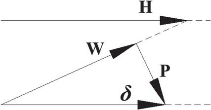
Figure 1 PPE introduces a protective vector P ensuring the worker path remains parallel to hazard H.
P(t) represents the PPE’s protection, for example insulated gloves, countering the electric energy of an energized part.
Manufacturers of PPE are required to specify a theoretical lifespan for their products, reflecting the period over which the equipment maintains its protective properties under routine conditions. For instance, respirators may last up to 5 years, while safety helmets and gloves often have shorter lifespans depending on their materials and usage. These expiration dates must be determined based on the date of manufacture.
In contrast, in high-energy events such as an arc flash, which can reach temperatures around 19,000C, can cause the protective properties of PPE (e.g., arc-rated fabrics) to degrade almost instantaneously. To capture this behavior, the magnitude of the protective effect can be modelled using a step-function (1).
| (1) |
In this threshold-based model, the PPE maintains its full protective capacity up to the failure time (the time at which the incident energy exceeds the PPE’s rating). Once is reached, the PPE fails abruptly and its protective capacity drops to zero.
The arc flash boundary is defined in [6] as the distance from the arc source at which the incident energy equals 1.2 cal/cm, the level at which an unprotected worker could receive a second-degree burn. In our geometric model, this boundary represents the threshold beyond which the risk is deemed acceptable. The parameter in our model quantifies the additional effective safety distance provided by PPE. is interpreted as an effective safety distance (in “meters equivalent”) that the PPE can provide before any degradation occurs. For instance, if an unprotected worker must maintain a distance of 1 m from the arc source to stay below the 1.2 cal/cm incident energy threshold, then a worker physically positioned 0.5 m from the hazard would be in danger. However, if that worker wears PPE with m, the PPE adds an extra meter of safety. In this case, the worker’s effective safety distance becomes 1.5 m, which exceeds the 1-meter requirement.
Generally, actual values for will vary with the type of PPE: arc-rated suit, which protect large portions of the body, provides a greater effective safety margin, whereas insulated gloves or dielectric boots, which protect only localized areas, may offer a lower .
3 Equations for Non-intersecting Paths
The paper models both the hazard H(t) and the worker’s movement W(t) as time-dependent vectors. In simple terms, the hazard’s position over time is represented by a vector that starts at an initial point and then moves outward according to its velocity and acceleration. Similarly, the worker’s path is represented as a vector that begins at a safe distance and then changes as the worker move, taking into account their speed and any acceleration or deceleration (for instance, due to reaction time delays or fatigue) (2) and (3).
| (2) | |
| (3) |
where is the starting position of the hazard (e.g., location of an energized panel), is the velocity of the hazard (e.g., propagation of an arc flash), is the hazard acceleration (e.g., arc expansion; arc flash may propagate at increasing speeds due to material interactions), is the starting position of the worker (e.g., at a safe distance), is the velocity of the worker (e.g., approaching an energized panel), is the worker acceleration (e.g., workers may accelerate or decelerate, especially under fatigue or stress).
The typical average walking speed for most adults is generally around 1.4 ms [7]. For workers, the walking speed might be influenced by the need to reach destinations efficiently, for instance carrying tools, but it generally aligns with the average walking speeds observed in the general population.
The basic idea is that if the hazard’s expanding path (e.g., an arc flash) and the worker’s trajectory ever cross, then the worker becomes exposed to the hazard. To prevent this, the model requires that the worker’s path and the hazard’s path never intersect. For this to hold true, Equations (4) and (5) for non-intersecting paths must be simultaneously satisfied.
| (4) | |
| (5) |
The hazard and the worker should be moving in parallel directions. Mathematically, this means that the cross product of their velocity vectors is zero. When this condition is satisfied, it ensures that if they start from different positions, their paths will never merge even if they are on trajectories that run in the same direction.
It is also essential that the initial positions of the hazard and the worker are not the same. In other words, there must be a safe initial separation distance between the two. If they started at the same point, even if they move in parallel, their paths will coincide completely, leaving the worker fully exposed. The arc flash boundary introduced in [6] enforces , where d is the safe distance, satisfying Equation (5).
As an example, consider an exposed energized part at with (i.e., static hazard) within a substation. In addition, consider a worker at the initial position , who moves toward the panel with velocity . We will have:
| (6) |
The vectors are parallel, and the Equation (4) is satisfied.
The starting points are different but aligned on the x-axis. The intersection test can be performed, obtaining (7):
| (7) |
Equation (7) has a solution at t 5 s, that is, the worker will reach the hazard after 5 s. To prevent incidents, safety boundaries of extension d (e.g., arc flash boundaries [6]), such as H–W, and/or PPE (i.e., P) should be adopted to maintain safe distance from equipment.
4 Hierarchy of Controls as Geometric Transformations
In Euclidean geometry, the axioms are statements accepted as true without proof (e.g., a straight line can be drawn between any two points) and serve as the foundation for deriving theorems. Without these postulates, the entire geometric system becomes inconsistent or incomplete.
The Hierarchy of Controls prioritizes elimination, that is, removing hazards entirely as the highest-order control, followed by substitution, engineering controls, administrative controls, and finally PPE. Each subsequent layer is less effective and relies on the failure of the prior layer.
In analogy to the Euclidean geometry, the elimination is the “axiom” of the hierarchy of controls. It is the most fundamental and effective principle, as it removes risk at its source. If elimination is achievable, no further controls are needed, just as the Euclidean geometry built on the fifth postulate requires no additional axioms to define parallelism.
If we mirror the postulation approach of Euclidean geometry, we obtain:
• Elimination equals Axiom (irreducible foundation).
• Substitution, engineering controls, administrative controls, and PPE equal theorems and corollaries (i.e., derived solutions dependent on the axiom).
Each control layer is mapped to a geometric concept in Table 2.
Table 2 Mapping of controls to geometric concepts
| Control | Geometric Analogy | Physical Interpretation |
| Elimination | Remove H (axiom) | De-energization of system |
| Substitution | Scale H (theorem) | Lower voltage alternatives |
| Engineering Controls | Apply boundary constraint (theorem) | Arc-resistant switchgear, remote racking |
| Administrative Controls | Introduce procedural constraints (corollary) | Lockout/Tagout Reduce shift lengths |
| PPE | Introduce P (corollary) | Insulating gloves, arc suits |
Reference [8] considers elimination of the hazard (i.e., ) as the highest-priority control. If elimination of the hazard (e.g., de-energizing a system) is impossible or unsafe, “theorems” like substitution (e.g., replacing high-voltage equipment with lower-voltage alternatives) or engineering control are preferred. For example, arc-resistant switchgears can contain and redirect arc flash energy to protect personnel [10]. Similarly, remote racking systems allow workers to engage, disengage, and operate circuit breakers from outside the arc flash boundary. If all else fail, PPE (e.g., insulated gloves) should be adopted, but they are inherently less robust.
5 Human Factors and Behavioral Modeling
Human factors, such as fatigue, significantly influence electrical safety by altering worker behavior. While the geometric model focuses on physical separation of hazards H(t) and worker W(t) it can be extended to quantify fatigue’s impact on collision risk. Fatigue reduces a worker’s ability to maintain safe practices, altering movement patterns and neurocognitive performance. For example, a fatigued worker may move more slowly or erratically, increasing the likelihood of intersecting a hazard.
Reference [10] observed a 37% higher hazard rate for workers exceeding 12-hour shifts. Assuming this increase correlates with neurocognitive decline (e.g., slower reaction times, reduced situational awareness), we model worker velocity as:
| (8) |
where is the initial worker velocity (e.g., 1 m/s), and a fatigue coefficient, which can be derived from the 37% performance exponential decay over 12 hours as:
| (9) |
Although a slower approach might, in theory, delay the moment of hazard intersection, the overall increase in risk due to fatigue-related impairments (both physical and cognitive) typically outweighs any benefit of a slower approach. Fatigue can, in fact, cause irregular or unpredictable movement patterns. The lack of precision in movement could lead to unintended trajectories that increase the risk of intersecting the hazardous zone.
Risks can be decreased by limiting shifts to 8 hours (i.e., administrative controls) and enhancing protective measures (e.g., engineering controls).
6 Simulating an Arc Flash Scenario
Let us assume that an arc flash, originating in an electrical panelboard, starts from an initial radius and expands radially outward at a constant speed (Figure 2).
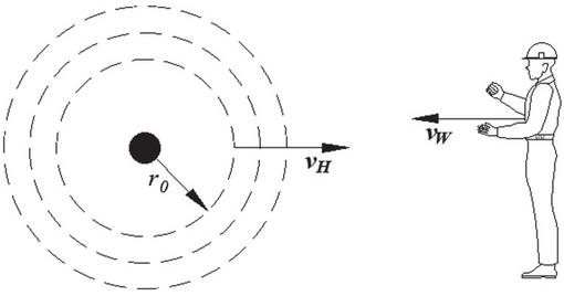
Figure 2 Arc flash expanding outward at a constant speed .
The concept of “radial speed” of an arc flash, that is, the expansion velocity of the arc plasma, is not directly addressed in standard calculations; however, we use it here as a geometric model of the hazard. Reference [6] provides equations to estimate the incident energy at various distances, which may be used to infer the rate of energy dispersion. In laboratory 3-phase arcing tests conducted at 600 V, [11] indicates that the plasma cloud reached its maximum extent, about 1m long, after 8.8 ms. However, plasma speed values in actual industrial systems may be lower. If the equipment is relatively small and the arc flash energy is concentrated near its surface, the initial radius might be comparable to the equipment’s dimensions. In general, however, is determined by the incident energy released during an arc flash and the resulting hazardous energy distribution.
We model the instantaneous arc flash radius with a simplified linear expansion model (10).
| (10) |
By expressing the arc flash contour as a function of time, we capture the hazard’s “reach” as it expands, which is analogous to drawing a circle with an increasing radius. This provides a clear geometric representation of how far the hazard extends at any moment. This visualization reinforces the core geometric principle: maintaining safe separation is equivalent to ensuring that the worker’s effective path does not “intersect” the hazardous region.
According to [6], a maximum arc flash duration of 2 s is used in calculations. This duration is assumed a reasonable time for a person to react and move away from the hazard if physically possible. In practice, however, workers may be unable to escape within this timeframe due to constraints such as confinement in a switchgear room.
We further assume that the worker starts at a safe distance from the panel and walks directly toward it at a constant speed . This represents a scenario, for example, during maintenance or troubleshooting when a worker is not aware of an arc flash initiation. The instantaneous distance of the worker from the panel is modeled as:
| (11) |
The above equation tracks the worker’s trajectory in space. In our geometric model, the worker’s path is a straight line, and (11) shows how that path approaches the hazard. It quantifies the movement and helps determine when (if at all) the worker’s path might intersect the hazardous zone.
Personal protective equipment (PPE) (e.g., insulated gloves, arc-rated suits) provides a protective “buffer” that, in geometric terms, effectively shifts the worker’s trajectory outward (away from the hazard) by a certain margin. However, the protection may abruptly decay over time due to material degradation (as described in Equation (1) of our model). As the PPE fails, this buffer shrinks, and the worker’s protection becomes insufficient.
We define the instantaneous worker’s effective distance as the sum of the worker’s current distance from the panel W(t) and the protective buffer provided by the PPE :
| (12) |
The worker is considered safe at time t if their effective distance exceeds the current arc flash radius:
| (13) |
This safety condition ensures that even as the arc flash expands and the PPE protection decays, the combined effect of the worker’s distance and the PPE’s mitigation is sufficient to keep the worker out of the hazardous energy zone.
A graph demonstrating when the worker’s effective distance falls short of the expanding hazard is provided in Fig. 3 with the following arbitrary parameters: m, ms, (the PPE is intact), m, ms.
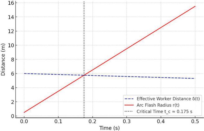
Figure 3 Effective safe distance and arc flash radius vs. time.
The critical time , at which the effective distance equals the arc flash radius, indicates that the worker’s PPE is just adequate. If the worker does not retreat or if the PPE degrades abruptly, the worker will be exposed to the hazardous energy.
With the given parameters, the critical time can be calculated with (14), which provides s.
| (14) |
To inform design and operational decisions, such as prioritizing enhancements in PPE performance or increasing safe working distances, the sensitivity analysis of the critical time is performed. This analysis systematically investigates how small variations in key model parameters affect the time at which a worker’s effective safe distance equals the expanding hazard boundary. The study demonstrates that the impact of worker movement speed () is relatively weak, owing to the much higher hazard expansion speed (). In fact, is identified as the most critical parameter; even small increases in significantly reduce , thereby diminishing the available critical time. The protective buffer () exhibits a moderate, linear impact on , and the initial worker position () has a moderate effect as well. Table III summarizes the sensitivity trends for the critical time with respect to various parameters.
Table 3 Summary of sensitivity trends
| Parameter | Effect on | Impact |
| (worker reaches hazard sooner) | weak | |
| (hazard expands faster) | strong | |
| (delays exposure) | moderate (linear) | |
| (worker starts farther away) | moderate |
Safety can be improved minimizing by employing faster protective devices to extend . Maximizing the safe working distance and improving (i.e., using higher-rated PPE) is a secondary defense but still useful for small improvements in .
It is important to note that this model focuses exclusively on the geometric expansion of the arc flash hazard, represented by the expanding radius . This approach provides a useful baseline for understanding the relative dynamics between the hazard’s expansion and the worker’s effective distance (including the mitigating effects of PPE). This geometric interpretation not only clarifies the interplay between these variables but also suggests practical interventions: increasing the initial distance from the hazard or improving PPE durability effectively “pushes” the worker’s path further away from the danger zone, preserving the non-intersection condition.
However, in an actual arc flash event, several additional factors, such as intense heat radiation, pressure waves generated by the rapid expansion, the release of toxic fumes, intense flash, and shrapnel, can significantly influence the severity of injuries and the overall hazard. While these factors can be incorporated into more complex models, their exclusion in the present work represents a simplification. This limitation is acceptable for a basic, first-order model aimed at establishing the foundational geometric relationships, but it should be kept in mind when applying the model to real-world scenarios. Future work may extend the model to include these additional layers of hazard.
Equation (13) is the core safety condition in the geometric model. It asserts that if the sum of the worker’s distance and the PPE’s protective “push” is greater than the arc flash radius, the worker’s exposure vector does not intersect the hazard vector. This condition encapsulates the fundamental geometric idea of parallel lines, where maintaining separation (or a safe buffer) prevents hazardous interaction.
7 Conclusion
This paper presents a novel geometric paradigm for electrical safety by modeling both hazards and worker exposures as time-dependent vectors. In our framework, the hazard, exemplified by an arc flash, is represented as an expanding boundary, while the worker’s movement is depicted as a straight-line trajectory. Safety is achieved when the worker’s effective distance, which combines their physical separation from the hazard with the protective buffer provided by PPE, remains outside the hazardous zone.
Our model emphasizes that maintaining non-intersecting paths between the hazard and the worker is crucial for ensuring safety. This concept is rooted in the geometric principle of parallel lines that never meet, where a sufficient initial separation and an adequate PPE buffer prevent hazardous exposure. We further illustrate that risk is highly sensitive to key parameters: increases in worker speed, erratic movements due to fatigue, or hazard expansion speed significantly shorten the available reaction time, while improvements in the initial safe distance or PPE performance extend it.
Additionally, the integration of the Hierarchy of Controls into the geometric framework demonstrates that eliminating the hazard (e.g., via de-energization) is the most effective approach, with substitution, engineering controls, administrative measures, and PPE serving as successive layers of defense. The model also acknowledges human factors, such as fatigue, that can increase the likelihood of exposure.
While our analysis focuses solely on the geometric expansion of hazards to provide a clear, first-order risk assessment, we recognize that additional factors (such as heat radiation, pressure waves, and toxic fumes) also play critical roles in real-world arc flash events. This simplification serves as a robust foundation for future work aimed at incorporating these complexities.
In summary, by leveraging the Euclidean postulate of non-intersecting lines, an intuitive and quantitative basis for assessing electrical safety and developing improved risk mitigation protocols is offered.
References
[1] 29 CFR 1904 Subpart G “Definitions.”
[2] Euclid, “Euclid’s Elements,” Book 1, Definition 23. 300 BCE.
[3] NFPA 70E “Standard for Electrical Safety in the Workplace,” 2024.
[4] 29 CFR Part 1910.147, “The Control of Hazardous Energy.”
[5] 29 CFR 1926.28 “Personal Protective Equipment.”
[6] IEEE 1584-2018: “Guide for Performing Arc-Flash Hazard Calculations.”
[7] Mohler, B.J., Thompson, W.B., Creem-Regehr, S.H. et al. “Visual flow influences gait transition speed and preferred walking speed.” Exp Brain Res 181, 221–228 (2007).
[8] National Institute for Occupational Safety and Health (NIOSH).
[9] IEEE C37.20.7-2017: “IEEE Guide for Testing Switchgear Rated Up to 52 kV for Internal Arcing Faults.”
[10] Dembe AE, Erickson JB, Delbos RG, Banks SM, “The impact of overtime and long work hours on occupational injuries and illnesses: new evidence from the United States.” Occup Environ Med. 2005 Sep; 62(9):588–97.
[11] R. Wilkins, M. Allison and M. Lang: “Effect of Electrode Orientation in Arc Flash Testing,” Mersen, 2005.
Biography

Massimo Mitolo (Fellow, IEEE; Fellow, IET; IEEE-HKN), a distinguished scholar and scientist, has been bestowed the Knighthood in the Order of Merit of the Italian Republic in acknowledgment of his exceptional contributions to scientific endeavors that have brought great honor to the nation. He is renowned for his remarkable achievements in the field of electrical engineering.
Sir Massimo earned his Ph.D. in Electrical Engineering from the University of Napoli “Federico II” in Italy. His unwavering dedication and significant impact on the field have led to his recognition as a Fellow of IEEE “for contributions to the electrical safety of low- voltage systems”. Furthermore, he holds the distinguished title of Fellow from the Institution of Engineering and Technology (IET) in the U.K. and is a member of the IEEE-HKN Honor Society. Additionally, he is a registered Professional Engineer in both the state of California and Italy.
Dr. Mitolo serves as a Full Professor of Electrical Engineering at Irvine Valley College in California. In addition to his academic responsibilities, he is a senior consultant specializing in the domains of failure analysis and electrical safety. His extensive research and industrial experience revolve around the comprehensive analysis and grounding of power systems, as well as electrical safety engineering.
Dr. Mitolo’s expertise is reflected in his publication record, encompassing over 190 journal papers, as well as the authorship of several influential books. Noteworthy titles authored by him include “Electrical Safety of Low-Voltage Systems” (McGraw-Hill, 2009), “Laboratory Manual for Introduction to Electronics: A Basic Approach” (Pearson, 2013), “Analysis of Grounding and Bonding Systems” (CRC Press, 2020), “Electrical Safety Engineering of Renewable Energy Systems” (IEEE Wiley, 2021), “Smart and Power Grid Systems: Design Challenges and Paradigms” (River Publishers, 2022), “Simulation-based Labs for Circuit analysis.” (River Publishers, 2024), “Principles and Practices of Electrical Safety Engineering: Ensuring Protection in Electrical Systems” (River Publishers, 2025).
His scholarly endeavors have garnered significant recognition, culminating in his inclusion in the World’s Top 2% Most-cited Scientists List, as compiled by Stanford University, since 2020.
Within the Industrial and Commercial Power Systems Department of the IEEE Industry Applications Society (IAS), Dr. Mitolo actively engages in various committees and working groups, demonstrating his commitment to advancing the field and fostering collaborative efforts.
Acknowledging his achievements, Dr. Mitolo has been the recipient of numerous prestigious accolades throughout his career. Notably, he has been honored with the IEEE Region 6 Outstanding Engineer Award and has garnered nine Best Paper Awards for his exceptional scholarly contributions. Furthermore, he has received recognitions such as the IEEE Ralph H. Lee I&CPS Department Prize Award, the IEEE I&CPS Department Achievement Award, and the James E. Ballinger Engineer of the Year Award from the Orange County Engineering Council in California.
Distributed Generation & Alternative Energy Journal, Vol. 40_3, 559–572.
doi: 10.13052/dgaej2156-3306.4035
© 2025 River Publishers