Protection Against Fault Currents in Photovoltaic Arrays: A Comprehensive Review
Massimo Mitolo
Electrical Engineering, Irvine Valley College, California, USA
E-mail: mmitolo@ivc.edu
Received 06 June 2025; Accepted 17 June 2025
Abstract
Fault currents in photovoltaic (PV) arrays present unique challenges for system designers, particularly when multiple strings are connected in parallel. This review consolidates fault-current modeling, international standards, and practical guidelines to establish a comprehensive protection framework for PV installations. In this paper, single-string and multi-string fault scenarios are analyzed, deriving expressions for short-circuit and reverse-current contributions under high-irradiance conditions. Using international standards as reference points, the conditions under which string-level overcurrent protective devices become mandatory is quantified.
Conductor ampacity requirements are shown to inherently satisfy “overload” protections if cable sizing exceeds maximum design current per string; however, in unfused configurations, cable ratings must be verified against the worst-case reverse-current from healthy strings.
The paper also addresses the a.c. – side short-circuit protection, noting inverter contributions and grid-sourced fault currents. Finally, commissioning and inspection procedures are outlined to ensure compliance with labeling and protection mandates. The findings support safer, more cost-effective PV system design and highlight areas for future research in advanced power-electronic topologies and dynamic fault behaviors.
Keywords: a.c. fault protection, conductor ampacity, DC back-feed, fault current modeling, multi-string PV, overcurrent protection, photovoltaic arrays, reverse current, string fuse selection, system inspection.
1 Introduction
Photovoltaic (PV) systems have evolved substantially in terms of both capacity and architectural complexity. Modern utility-scale and commercial installations utilize multiple parallel string configurations to maximize power output and system efficiency. However, the increased prevalence of parallel-connected PV modules introduces significant safety considerations, particularly regarding fault current behavior and overcurrent protection. A critical issue is understanding how parallel strings interact during fault conditions and implementing appropriate protection strategies to prevent equipment damage and ensure personnel safety.
PV modules operate as current-limited sources under standard test conditions (STC). However, when modules are connected in parallel strings and, in some installations, also to battery energy storage, abnormal currents can arise during fault events. Healthy strings contribute “reverse” currents into a faulted string, potentially exceeding cable ampacity and module reverse-current ratings.
This paper first examines fault current behavior within a single string, then extends the analysis to multi-string and multi-subarray configurations to quantify reverse-current contributions. Based on these calculated fault currents, the selection of appropriate overcurrent protective devices in accordance with relevant standards and literature is illustrated.
Specifically, Section 2 analyzes short-circuit currents in PV string and subarray cables, deriving expressions for fault-current contributions from both the faulted string and healthy strings. Section 3 addresses module-level reverse-current protection, detailing the conditions under which string-fuses become necessary. Section 4 discusses d.c. protective-device sizing, including fuse-selection criteria and the effect of battery back-feed in hybrid systems. Section 5 covers a.c. side short-circuit protection for inverter output conductors. Finally, Section 6 presents field inspection and verification procedures to ensure compliance with applicable standards on PV installations.
By consolidating standards, theoretical fault-current models, and practical design guidelines, this review provides a comprehensive reference for PV system designers and installers to ensure safe and reliable operation under fault conditions.
2 Short-circuit in PV String Cables
According to [1, 2], in normal operation, the maximum design current I to be considered for a photovoltaic (PV) device is defined by:
| (1) |
where I denotes the module’s nameplate short-circuit current, as specified by the manufacturer under standard test conditions (STC), which include an irradiance of 1,000 W/m, atmospheric air mass (AM) of 1.5, and an ambient temperature of 25C. Since PV strings consist of modules connected in series, the short-circuit current of a string is also equal to I. The multiplier of 1.25 accounts for potential increases in output current due to inhanced irradiance conditions beyond STC (e.g., snow reflection).
To ensure safe operation and prevent insulation damages, PV cables must be selected with an ampacity I (i.e., current-carrying capacity) that is equal to or greater than the value specified by (1).
A PV string cable interconnects the modules within a string and links the string to the combiner box [3]. As illustrated in Figure 1, in the event of a short-circuit at point X in a cable string, fault currents from multiple sources contribute to the fault.
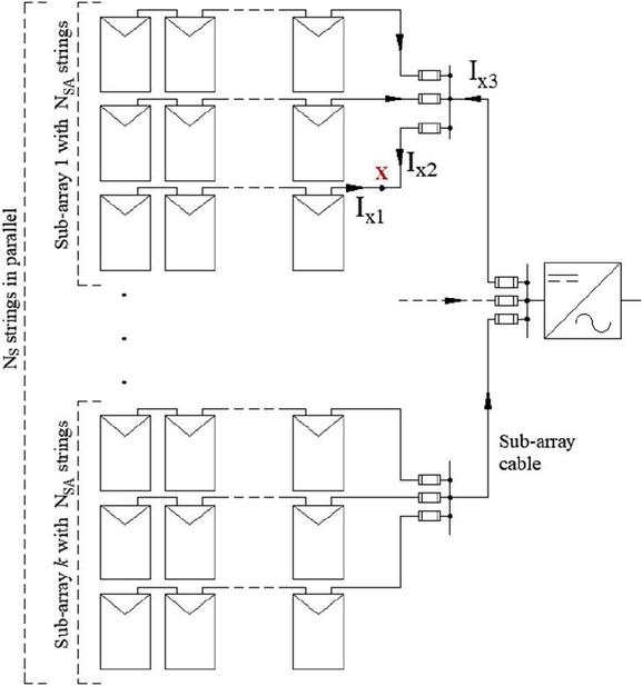
Figure 1 Fault-currents due to a short-circuit in a string cable at point X.
These contributions are described by:
| (2) | |
| (3) | |
| (4) |
where N is the total number of parallel-connected strings in the array, N is the number of strings in the sub-array affected by the fault, and k sub-arrays are present in the configuration.
The current I represents the fault current from the faulted string, limited by its own short-circuit characteristics and enhanced irradiance conditions, as defined in (1). The fault current I represents the current contribution from the (N) healthy strings in the array. I is the current flowing from the other sub-arrays, which is the total number of strings minus the number of strings in the faulted sub-array (NN).
In systems with only two parallel strings (N) and no battery storage, I coincides with the intended string cable’s design current, which must be within the cable’s ampacity. Therefore, if the string cable is properly sized, no overload can occur, and overcurrent protection is not required.
However, in configurations with three or more parallel strings (N), the current I exceeds the string cable’s design current I and possibly its ampacity I. This will require the use of overcurrent protective devices. For instance, in a system with three strings (N), I, which is twice the design current I given in Equation (1) and may also be greater than the rated ampacity of the string cable.
More generally, the maximum number of strings, , that can be connected in parallel without overcurrent protection is determined by the specific ampacity of the string cable, I. Protection is not required as long as I does not exceed I. This relationship is defined by:
| (5) |
Using string cables with a higher ampacity (e.g., for voltage drop considerations) could allow for more strings to be connected without protection.
2.1 Cost Optimization: Enhanced Cable Ampacity vs. String-Level Fuses
A critical design decision in multi-string PV arrays is choosing the most economical method for overcurrent protection without compromising safety.
Adopting greater cross-section cables increases their cost per unit of length. There might also be minor increases in labor for handling heavier or stiffer cables, or for larger conduit, if required. Adopting string-level fuses introduces an incremental cost per string, which includes the cost of the fuse itself, the fuse holder, and the labor to install these components, usually within combiner boxes. Larger or more numerous combiner boxes might also be needed to accommodate the fuses, adding to the balance-of-system costs.
If the number of parallel strings (N) is just slightly above the threshold where protection might be needed (e.g., 3–4 strings), employing a slightly thicker gauge cable for all strings might be more economical than the cumulative cost of fuses, holders, and installation labor for each string. This is especially true if other factors, like voltage drop minimization over long cable runs, already necessitate a larger cable gauge. In such cases, the “extra” ampacity for overcurrent protection might come with little to no additional cost beyond what’s already required for voltage drop.
Conversely, as N increases, the reverse current I may grow significantly and to rely solely on cable ampacity would require cables substantially large. The cost of such heavy-duty cabling for all strings would likely become prohibitive and impractical. In these situations, using standard-sized string cables, rated for at least 1.25Isc, in conjunction with appropriately sized string fuses becomes the more cost-effective and standard solution.
2.2 Sensitivity Analysis for N
Extreme environmental conditions, beyond typical high irradiance, may render the multiplier (1.25) approach not adequate for all scenarios.
Following is a sensitivity analysis of the maximum number of parallel strings (N) that can be connected without string-level overcurrent protection, based on varying I multipliers and different cable sizing strategies. The calculation is based on the condition for when overcurrent protection is not required, derived from Equation (5). The formula used is:
| (6) |
where R = I/I represents the cable sizing strategy; m is the I multiplier that accounts for potential increases in output current due to high irradiance conditions beyond STC. N must be an integer, so the floor of the calculation is taken. If the actual number of strings is greater than N, overcurrent protection is required.
Table 1 shows the results of the sensitivity analysis.
Table 1 Sensitivity analysis for N
| N | |||||
| R = I/I | 1.15 | 1.25 | 1.35 | 1.45 | 1.50 |
| 1.5 | 2 | 2 | 2 | 2 | 2 |
| 2.0 | 2 | 2 | 2 | 2 | 2 |
| 2.5 | 3 | 3 | 2 | 2 | 2 |
| 3.0 | 3 | 3 | 3 | 3 | 3 |
| 3.5 | 4 | 3 | 3 | 3 | 3 |
| 3.75 | 4 | 4 | 3 | 3 | 3 |
For R values of 2 or less, N is consistently 2 across all multipliers (i.e., m ranging from 1.15 to 1.50). This implies that if string cables are sized with an ampacity up to twice the nominal short-circuit current of the module, connecting more than two strings in parallel will necessitate overcurrent protection. As R increases (i.e., string cables are chosen with higher ampacity relative to I), N generally increases, as expected. A more robust cable can handle higher reverse currents from a larger number of healthy strings. To achieve N, the cable’s cross-section needs to be quite significant and this underscores that relying solely on cable ampacity to avoid fuses for systems with many parallel strings can lead to substantially larger and potentially more expensive cabling.
Since N represents a physical count of strings and is calculated using the floor function, its value changes in discrete steps rather than continuously. This means there are specific thresholds in the R/m ratio that dictate a change in N. For designers, this implies that a small increase in assumed m or a small decrease in R can sometimes be the deciding factor that pushes the design from not requiring fuses to requiring them for a particular string count.
It is important to emphasize that the sensitivity analysis presented herein is primarily concerned with the cable’s capacity to tolerate reverse currents. However, the final determination of overcurrent protection requirements must also ensure compliance with the PV module’s maximum allowable overcurrent protection rating, as discussed in a subsequent section.
3 Short-circuit in PV Sub-array Cables
PV sub-array cables carry the output current of their associated sub-arrays to a common dc bus or inverter input (Figure 2). The appropriate maximum design current for a sub-array cable is, therefore, N.
In the event of a short-circuit at point Y in a sub-array cable (as depicted in Figure 2), fault currents from all sub-arrays contribute to the fault.
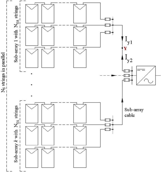
Figure 2 Fault-currents due to a short-circuit in a sub-array cable at point Y.
These contributions can be described by the following equations:
| (7) | |
| (8) |
Here, I represents the fault current from the strings of the sub-array whose cable is experiencing the short-circuit; the intensity of this current equals the sub-array cable’s maximum design current. The fault current I originates from the remaining strings of the system. It is important to note that I can exceed the sub-array cable’s maximum design current if N. In such cases, the overcurrent protection can be omitted if, and only if, the sub-array cable has an ampacity greater than I.
4 Protection of PV Modules Against Reverse Currents
Reverse current is defined in [1] as a current that can flow in the reverse direction to normal into a PV module from parallel connected strings or sub-arrays as the result of a fault.
The protection of photovoltaic modules against reverse current is a critical consideration in the design of solar arrays, particularly in configurations involving multiple parallel strings. The risks include thermal damage, fire hazards, and the potential for permanent degradation of the module. The maximum current that a PV module can withstand in the reverse direction (I), defined in [4], must be obtained from the manufacturer. For crystalline silicon modules, a typical value for I ranges between 2 and 2.6 times the module’s nameplate short-circuit current (I) at Standard Test Conditions.
Figure 3 illustrates a floating PV system configuration, in which the array is electrically isolated from ground. The system consists of N strings in parallel and the diagram depicts the occurrence of a double ground fault.
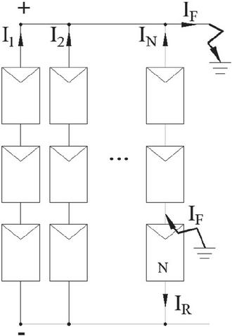
Figure 3 Floating PV array affected by double ground fault.
In the event of a single ground fault, the PV array ceases to be electrically floating, thereby elevating the risk of electric shock. Should a second ground fault occur, the ground fault loop becomes complete, enabling fault currents to circulate through the modules in the reverse direction.
In reference to Figure 3, the reverse current (I) flows through module N and through the segment of the string cable that connects it to the negative bus bar. Its magnitude is the sum of the maximum currents contributed by the (N) healthy strings:
| (9) |
I increases by I for each additional parallel PV string in the array.
The string overcurrent protection is required when the total reverse current circulating through the PV module exceeds I [1], which denotes the module’s maximum overcurrent protection rating [3], representing the highest current the module can safely withstand without sustaining damage. Reference [5] defines I as 1.35 times the maximum reverse current rating (I) of the PV module.
The “1.35” multiplier comes from the PV-module safety qualification [5] (i.e., the Reverse-Current Overload Test). The PV module is proven safe up to 1.35I, therefore, protection is required whenever the reverse current from other strings exceeds that level.
In formulae, the maximum number of parallel strings (N) above which overcurrent protection is necessary is given by:
| (10) |
For a crystalline silicon module with I, the over-current protection is required when more than three strings are connected in parallel.
It is important to note that blocking diodes are not considered a reliable method for protecting against reverse current. Their use is currently restricted to specific applications, such as preventing the discharge of batteries into an unenergized PV array during nighttime conditions.
5 Sizing and Installation of d.c. Protective Devices
Fuses are the most commonly employed devices for overcurrent protection in PV strings and arrays. These protective devices must possess a voltage rating greater than or equal to the maximum open-circuit voltage (V) of the PV system, including possible overvoltages from cold-weather V rise. In PV applications, direct current rated type “gR” fuses [6], typically installed within combiner boxes, are widely used. These fuses must be capable of interrupting both the full-load current and the prospective fault currents originating from the PV array and any additional power sources, such as batteries, if present.
According to [2], overcurrent protection devices must be rated at no less than 125% of the maximum design current, (i.e., I). Consequently, the minimum required fuse rating for a string is , which accounts for operational current variations and prevents nuisance tripping while ensuring adequate protection. To ensure effective fault protection from other PV sections or battery systems, fuses must be installed at the load end of each string (Figures 1 and 2).
In floating PV array configurations, overcurrent protection must be applied to both conductors. This requirement stems from the potential for both the positive and negative poles to conduct fault current in the event of a double ground fault. In contrast, for grounded PV arrays, it is sufficient to install the overcurrent protective device only on the ungrounded (live) conductor. This is because a ground fault occurring on the grounded conductor does not result in fault current circulation, due to its direct connection to earth potential.
Furthermore, [1] indicates that various climatic and environmental factors can cause the string’s output current to exceed their standard test condition values. These factors may include high solar irradiance in certain geographic regions, snow-induced reflection, and other site-specific conditions. These sustained overcurrents do not result from faults but are caused by operating conditions. Therefore, [1] stipulates that for protection against overload, the protective device’s current rating I for a string must satisfy the following conditions:
| (11) | |
| (12) |
The lower bound factor of 1.5 accounts for elevated irradiance conditions, which aligns with [2].
6 Back-feed Currents
Under fault conditions, d.c. back-feed currents may occur when inverters and/or external energy sources, such as battery storage systems, inject current into the PV array, as illustrated in Figure 4.
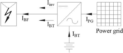
Figure 4 Back-feed currents from inverters and/or external sources.
The term back-feed, as defined in [1], specifically refers to current flowing into the PV array from sources external to the photovoltaic generation itself. This differs from PV reverse current, which is limited to the redistribution of current between parallel-connected PV strings in the event of a fault.
Unlike reverse currents, which originate from other parts of the PV array, back-feed currents come from non-PV sources, such as the power grid, through the inverter, or battery systems, and must be considered during system design, particularly for overcurrent protection coordination, cable and conductor sizing, compliance with fault withstand requirements.
Inverter manufacturers typically provide documentation of back-feed current magnitudes, as measured during type testing procedures [7]. For grid-tied inverters, specifications generally indicate negligible back-feed currents, often reported as zero or less than 0.1 A. In contrast, hybrid inverters, particularly those integrated with battery storage systems, may exhibit significantly higher back-feed currents, with datasheets reporting values up to 600 A d.c. Inverters are not designed to intentionally delay the cessation of internal back-feed once a fault is detected; rather, the inverter-contributed back-feed current typically ceases within 5 to 10 grid cycles following fault detection.
If the system includes battery storage, the inverter’s test report should indicate whether back-flow from the battery (I) into the PV array is possible, or whether it incorporates anti-back-feed mechanisms such as relays or blocking diodes.
As illustrated in Figure 4, the total back-feed current I is the sum of all non-PV current contributions. However, these contributions may not coincide temporally, and their duration and magnitude may vary depending on the control strategy, converter topology, and protection latency of each source.
The combined back-feed from inverter and battery affects the dc-side protection design. A short on a PV string sees multiple sources: the string’s modules plus the battery/inverter contribution. Hence, string fuses (or d.c. circuit breakers) must be sized to clear the sum of these currents without relying on the inverter’s internal protection.
7 Protection Against a.c. Short-Circuit Currents
The a.c. PV supply cable, which connects the AC terminals of the inverter to the distribution board of the electrical installation, must be protected against the effects of short-circuits (Figure 5).
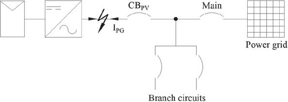
Figure 5 Fault on the a.c. PV supply cable.
Protection is achieved via a circuit breaker placed at the distribution panel (CB). According to [8], the inverter’s fault current contribution is typically limited to no more than twice its rated output and is often rapidly disconnected by its internal circuitry. Therefore, in the event of a short-circuit in the a.c. supply cable, the utility grid becomes the only significant source of sustained fault current.
8 Inspection and Compliance of the PV Overcurrent Protection System
The field verification of over-current protection, as specified in [9], involves a thorough inspection of the protective measures implemented within the photovoltaic system.
All markings on PV modules that are relevant for identifying key parameters necessary for field verifications, such as short-circuit current (I) and open-circuit voltage (V), must be clearly legible. These markings must be durable under conditions of normal use. Compliance is verified by inspection and by subjecting the markings to a durability test: rubbing the label manually with medium pressure for 15 s using a cloth soaked in water, followed by another 15 s using a cloth soaked in petroleum spirits. After this procedure, the markings shall remain legible, and marking plates must not be easily removable or exhibit curling.
For PV strings that do not incorporate over-current protective devices, it must be verified that the module’s maximum over-current protection rating (I) exceeds the worst-case reverse current. During commissioning, inspectors cross-check the module datasheet, documenting I and the maximum reverse current rating (I) against the number of parallel strings installed and apply Equation (9). If the condition is violated, string fuses or equivalent over-current protective devices must be present. This approach aligns with analyses of PV overcurrent protection challenges, which underscore the importance of ensuring module fuse ratings adequately cover multi-string reverse-current scenarios [10, 11].
Additionally, it must be verified that string cables ampacity is equal to, or greater than the maximum fault current resulting from the combined contribution of all parallel-connected strings under specified temperature and installation conditions. Therefore, field personnel will verify that the printed cable size and insulation type match the design documentation submitted for commissioning. In the absence of string over current protection, inspectors calculate the prospective fault current from (N, and compare it against the conductor’s rated ampacity per applicable standards [12] and relevant national wiring rules [2].
Combiner boxes and junction enclosures are also inspected to confirm that any installed over current protective device (e.g., type “gR” d.c. fuses) are correctly sized for the system’s maximum open-circuit voltage and interrupting rating. Inspectors verify that fuse labels match the fuse’s current rating and that fuse holders are properly rated for d.c. use at the expected system voltage.
All inspection findings must be documented in the commissioning report, as required by [9]. This dossier provides traceable evidence that the PV system complies with safety requirements and that any absence of string over current protection is justified by the module’s internal capability and cable’s ampacity. Reviews of protection challenges in PV systems [13] implies that such detailed documentation is essential for maintenance and fault diagnosis.
9 Conclusion
The analysis presented in this paper demonstrates that fault currents within PV arrays can be accurately characterized by combining module-level short-circuit behavior with multi-string reverse-current contributions. By deriving closed-form expressions for single-string and parallel-string fault scenarios, it was shown that healthy strings can inject significant reverse current into a faulted string, possibly exceeding both conductor ampacity and module reverse-current ratings. Applying the reverse-current threshold, this paper confirms that crystalline-silicon modules require string-level fuses when more than three strings are paralleled. This finding provides a clear, quantitative basis for specifying overcurrent protective devices in multi-string PV systems.
Cable sizing was shown to inherently safeguard against overload conditions, since properly selected conductors tolerate expected PV operating currents even under high irradiance, thereby satisfying overload protection exemption.
However, when string fuses are omitted, it remains imperative to validate that each conductor’s ampacity exceeds the worst-case reverse-current from healthy strings. Commissioning procedures ensure that cable selections and installation conditions prevent thermal damage during fault events. In practice, this approach streamlines field inspections and avoids unnecessary fusing when conductor sizing alone is sufficient.
In installations with batteries, back-feed currents from batteries and inverters can substantially increase the total d.c. fault current. By incorporating inverter and battery contributions into fuse-sizing calculations, designers avoid reliance on inverter internal protections and ensure that PV-side protective devices operate first. This coordination mitigates the risk of delayed fault interruption and potential damage to module strings or associated wiring.
This paper provides the consolidation of technical standards’ requirements with fault-current models to provide a unified design and verification framework. By translating complex standard requirements into explicit, field-applicable guidelines, the paper facilitates safer and more cost-effective PV installations. However, several limitations deserve attention and further study. First, the analysis assumes uniform module performance and neglects the effects of partial shading or module mismatch, which can alter reverse-current distributions in real-world arrays. Second, emerging power-electronic topologies, such as module-level electronics, and advanced microinverters, introduce dynamic fault behaviors that may not conform exactly to traditional fuse-based protection logic.
Researchers and practitioners alike can leverage the insights herein illustrated to optimize protective measures, reduce system downtime, and enhance overall safety in the rapidly growing photovoltaic industry.
References
[1] IEC 60364-7-712:2017, “Low voltage electrical installations – Part 7-712: Requirements for special installations or locations – Solar photovoltaic (PV) power supply systems.”
[2] NFPA 70, National Electrical Code, 2023.
[3] IEC 62548-1:2023, “Photovoltaic (PV) arrays – Part 1: Design requirements.”
[4] IEC TS 62257-7:2017, “Recommendations for renewable energy and hybrid systems for rural electrification – Part 7: Generators.”
[5] IEC 61730-2:2023, “Photovoltaic (PV) module safety qualification – Part 2: Requirements for testing.”
[6] IEC 60269-4:2024, “Low-voltage fuses – Part 4: Supplementary requirements for fuse-links for the protection of semiconductor devices.”
[7] IEC 62109-2:2011, “Safety of power converters for use in photovoltaic power systems – Part 2: Particular requirements for inverters.”
[8] De Almeida, L.R., da Costa Lima, R.N., Macedo Junior, J.R.: “Analysis of fault current contributions from small-scale single-phase photovoltaic inverters and their impacts on the protection of electric power distribution systems.” IET Gener. Transm. Distrib. 18, 1343–1359 (2024).
[9] IEC 62446-1:2016, “Photovoltaic (PV) systems – Requirements for testing, documentation and maintenance – Part 1: Grid connected systems – Documentation, commissioning tests and inspection.”
[10] Y. Zhao, J. -F. de Palma, J. Mosesian, R. Lyons and B. Lehman, “Line-Line Fault Analysis and Protection Challenges in Solar Photovoltaic Arrays,” in IEEE Transactions on Industrial Electronics, vol. 60, no. 9, pp. 3784–3795, Sept. 2013.
[11] Dhanup S. Pillai, N. Rajasekar, “A comprehensive review on protection challenges and fault diagnosis in PV systems,” Renewable and Sustainable Energy Reviews, Volume 91, 2018, Pages 18–40.
[12] IEC 60287-1-2:2023, “Electric cables – Calculation of the current rating – Part 1-2: Current rating equations (100 % load factor) and calculations of losses – Sheath eddy current loss factors for two circuits in flat formation.”
[13] M. J. Albers and G. Ball, “Comparative Evaluation of DC Fault-Mitigation Techniques in Large PV Systems,” in IEEE Journal of Photovoltaics, vol. 5, no. 4, pp. 1169–1174, July 2015.
Biography

Massimo Mitolo, a distinguished scholar and scientist, has been bestowed the Knighthood in the Order of Merit of the Italian Republic in acknowledgment of his exceptional contributions to scientific endeavors that have brought great honor to the nation. He is renowned for his remarkable achievements in the field of electrical engineering.
Sir Massimo earned his Ph.D. in Electrical Engineering from the University of Napoli “Federico II” in Italy. His dedication and significant impact on the field have led to his recognition as a Fellow of IEEE “for contributions to the electrical safety of low-voltage systems”. Furthermore, he holds the title of Fellow from the Institution of Engineering and Technology (IET) in London, United Kingdom, and is a member of the IEEE-HKN Honor Society. Additionally, he is a registered Professional Engineer in both the state of California and Italy.
Presently, Dr. Mitolo serves as a Full Professor of Electrical Engineering at Irvine Valley College in California. In addition to his academic responsibilities, he is a consultant specializing in the domains of failure analysis and electrical safety. His research and industrial experience revolve around the analysis and grounding of power systems, as well as electrical safety engineering.
Dr. Mitolo’s expertise is reflected in his publication record, encompassing more than 190 journal papers, as well as the authorship of several influential books. Noteworthy titles authored by him include “Electrical Safety of Low-Voltage Systems” (McGraw-Hill, 2009), “Laboratory Manual for Introduction to Electronics: A Basic Approach” (Pearson, 2013), “Analysis of Grounding and Bonding Systems” (CRC Press, 2020), “Electrical Safety Engineering of Renewable Energy Systems” (IEEE Wiley, 2021), “Smart and Power Grid Systems: Design Challenges and Paradigms” (River Publishers 2022), and “Simulation-based Labs for Circuit analysis.” (River Publishers, 2024), and “Principles and Practices of Electrical Safety Engineering: Ensuring Protection in Electrical Systems,” (River Publishers, 2025).
His scholarly endeavors have garnered significant recognition, such as the inclusion in the World’s Top 2% Most-cited Scientists List since 2020, as compiled by Stanford University.
Within the Industrial and Commercial Power Systems Department of the IEEE Industry Applications Society (IAS), Dr. Mitolo actively engages in various committees and working groups.
Acknowledging his achievements, Dr. Mitolo has been the recipient of numerous prestigious accolades throughout his career. Notably, he has been honored with the IEEE Region 6 Outstanding Engineer Award and has garnered nine Best Paper Awards for his exceptional scholarly contributions. Furthermore, he has received recognitions such as the IEEE Ralph H. Lee I&CPS Department Prize Award, the IEEE I&CPS Department Achievement Award, and the James E. Ballinger Engineer of the Year Award from the Orange County Engineering Council in California.
Distributed Generation & Alternative Energy Journal, Vol. 40_4, 437–654.
doi: 10.13052/dgaej2156-3306.4041
© 2025 River Publishers