Low-Voltage Ride-Through Technology of Distributed Photovoltaic Inverters Based on Model Predictive Current Control
Yusen Cheng1,* and Tao Li2
1Hubei University of Technology Detroit Green Technology Institute, Wuhan 430068, Hubei, China
2Wuhan Yingding Qizhi Xuzhan Education Consulting Co., Ltd, Wuhan, Hubei, China
E-mail: 13863769387@163.com
*Corresponding Author
Received 14 January 2026; Accepted 09 February 2026
Abstract
This paper proposes a low-voltage ride-through (LVRT) control strategy for distributed photovoltaic (PV) inverters based on model predictive current control (MPCC). A complete system model is established from the three-phase L-filter plant to its dq-frame representation, followed by discrete-time prediction and switching-state optimization. An LVRT-oriented current reference allocation mechanism is integrated to enable rapid active power curtailment and dynamic reactive injection during grid voltage sags. Unlike conventional PI–SVPWM schemes, the proposed MPCC directly evaluates all voltage vectors each sampling period, eliminating cascaded loops and improving transient response. Simulation studies verify that the method ensures stable current tracking under deep voltage disturbances, reduces harmonic distortion, suppresses DC-link fluctuations, and achieves fast post-fault recovery. A 1 kW hardware prototype further demonstrates real-time feasibility, achieving sub-millisecond dynamic reaction, low THD during LVRT, and significantly reduced overshoot compared with PI-controlled benchmarks. These results confirm that MPCC provides an effective and robust LVRT solution for modern grid-connected PV systems, offering improved dynamic performance, enhanced power quality, and strong grid-code compliance.
Keywords: Model predictive current control, photovoltaic inverter, low-voltage ride-through, grid-connected converter, DC-link stability.
1 Introduction
The rapid growth of distributed photovoltaic (PV) generation has significantly increased renewable penetration in modern power systems, reshaping traditional protection and operational practices. As inverter-interfaced PV replaces conventional synchronous generation, grid codes worldwide have introduced increasingly stringent fault ride-through requirements to ensure stable system operation during grid disturbances. In particular, low-voltage ride-through (LVRT) capability has become a mandatory requirement in many grid standards, requiring PV inverters to remain connected during short-term voltage sags rather than disconnecting [1]. From a broader system perspective, the high penetration of inverter-based distributed generation fundamentally changes grid protection and stability characteristics, making coordinated ride-through behavior essential to prevent widespread generation loss and maintain reliability [2, 3].
During grid faults or abrupt load variations, PV inverters operating under LVRT conditions are required to inject controlled active and reactive currents within prescribed limits [4] in order to support voltage recovery and maintain overall system security [5]. Practical LVRT strategies must therefore balance fast reactive current injection with active power curtailment to avoid inverter overcurrent and DC-link overvoltage, particularly under deep voltage sags [6]. Conventional proportional–integral (PI) current control combined with space-vector pulse-width modulation (SVPWM), although widely adopted in commercial PV inverters, exhibits limited transient bandwidth and delayed disturbance response due to cascaded control loops and modulation latency [7, 8]. These limitations become more pronounced under asymmetric or fast-changing fault conditions, where coupling between the d- and q-axis control channels can degrade current tracking accuracy and increase harmonic distortion [4, 9].
To address these challenges, a wide range of LVRT enhancement strategies has been reported. Traditional vector control using PI regulators remains the baseline solution in many industrial PV inverters due to its simplicity and established design methodology; however, its performance deteriorates significantly during deep voltage sags and weak-grid conditions [3, 7]. More advanced approaches, including droop-based control [10], coordinated reactive power support [11], and virtual inertia emulation [12], have been explored to improve voltage regulation and dynamic stability in high-penetration or microgrid environments. In parallel, adaptive control and nonlinear techniques – such as observer-based and sliding-mode approaches – have been proposed to improve robustness against grid asymmetry and reduce current distortion during LVRT operation [13, 14]. Despite these advances, many existing LVRT solutions continue to rely on cascaded control structures and separate modulation stages, increasing implementation complexity and limiting transient effectiveness when fast current prioritization is required [8].
Model predictive control (MPC) has emerged as a promising alternative for power-electronic converter control due to its ability to directly optimize switching actions based on a predictive system model while explicitly handling system constraints. In particular, finite-control-set MPC (FCS-MPC) directly operates on the discrete switching states of the inverter, thereby eliminating the need for external modulation stages and cascaded inner control loops [15], which enables faster transient response and improved current tracking performance in grid-connected PV converters [16, 17]. Early studies have demonstrated that MPC-based strategies can significantly enhance LVRT performance by improving dynamic current regulation during voltage sags, especially in single-phase and two-stage PV inverter configurations [18, 19]. More recent work has extended MPC-based LVRT approaches to more complex system architectures, including multi-port PV systems and parallel PV–battery inverters operating under weak grid conditions, highlighting the flexibility of predictive control frameworks [20, 21]. In addition, finite-set MPC has been applied to hybrid renewable systems and multilevel inverter topologies, where its ability to directly select optimal switching states contributes to improved transient behavior and power quality during grid disturbances [22, 23]. Despite these advances, many reported MPC-based LVRT implementations primarily emphasize steady-state current regulation or specific fault scenarios, while practical aspects such as LVRT-oriented current prioritization, simplified controller structure, and comprehensive experimental validation remain insufficiently addressed [15, 24].
Despite the extensive body of work on LVRT enhancement for PV inverters, several key challenges remain unresolved. Many existing strategies improve specific aspects of LVRT performance, such as voltage support or harmonic suppression, but often at the cost of increased control complexity or extensive parameter tuning. In particular, approaches based on cascaded control loops and external modulation stages may struggle to simultaneously achieve fast transient response, robust stability across a wide range of voltage sag depths, and straightforward practical implementation. Moreover, LVRT requirements are frequently handled through auxiliary control layers or mode switching, which can complicate controller design and degrade performance during rapid fault transitions. As a result, developing an integrated LVRT control strategy that combines predictive current regulation, minimal tuning effort, and direct enforcement of grid-code requirements remains an open challenge for distributed PV systems.
In this work, a model predictive current control (MPCC) strategy is proposed to address these limitations and enhance the low-voltage ride-through capability of distributed photovoltaic inverters. By directly optimizing inverter voltage vectors at each sampling instant, the proposed method eliminates cascaded PI regulators and modulation stages, enabling fast transient response and simplified controller structure. An LVRT-oriented current allocation mechanism is explicitly embedded within the predictive control framework to prioritize reactive current injection and active power curtailment during grid faults, thereby supporting grid voltage recovery while preventing DC-link overvoltage. The effectiveness of the proposed approach is demonstrated through comprehensive simulation studies and hardware experiments, which show improved dynamic behavior, reduced harmonic distortion, and more stable LVRT operation compared with a conventional PI–SVPWM baseline. These results indicate that the proposed MPCC-based strategy provides a practical and high-performance solution for LVRT operation in grid-connected PV systems.
The proposed approach distinguishes itself from existing LVRT control strategies in both formulation and implementation. Unlike conventional LVRT methods that rely on cascaded PI regulators, auxiliary control layers, or mode switching to satisfy fault ride-through requirements, the proposed method embeds LVRT functionality directly within a finite-control-set MPCC framework. The novelty of this work lies in three key aspects. First, an LVRT-oriented current reference allocation mechanism is explicitly integrated into the predictive control process, enabling seamless prioritization of reactive current injection and active power curtailment during voltage sags without additional supervisory logic. Second, by directly optimizing inverter voltage vectors at each sampling instant, the proposed MPCC eliminates modulation stages and inner current loops, achieving fast transient response and reduced tuning complexity under fault conditions. Third, the proposed strategy is validated through both detailed simulation and real-time hardware experimentation, demonstrating not only improved dynamic performance and harmonic suppression during LVRT events, but also practical feasibility for implementation in distributed PV inverters. These features collectively differentiate the proposed method from existing MPC-based LVRT approaches and highlight its contribution as an integrated, high-performance, and implementation-efficient solution.
2 System Modeling
The mathematical modeling of the grid-connected photovoltaic (PV) inverter is developed to form the basis of the proposed model predictive current control (MPCC) strategy for low-voltage ride-through (LVRT) operation. The distributed PV system considered in this work consists of a PV array, a DC-link stage, a three-phase voltage-source inverter (VSI), an output filter, and a point of common coupling (PCC) to the utility grid. The inverter interfaces renewable generation with the grid under normal operation, whereas during voltage sag events it must maintain current injection capability and provide reactive support in accordance with grid-code LVRT requirements. To enable predictive control with fast dynamic response, a control-oriented inverter model is derived in both abc and dq reference frames and discretized to obtain a finite-step current prediction model.
2.1 Structure of the Distributed PV Grid-Connected Inverter
A DC-linked three-phase VSI converts the PV output into AC power synchronized with the distribution grid. The DC-link capacitor stabilizes voltage fluctuations caused by irradiance changes, and the inverter output is connected to the grid through an L-type filter consisting of series inductance and a parasitic resistance . Let the inverter terminal voltage determined by the switching state be , the grid voltages be , and the filter currents be . Neglecting high-frequency switching harmonics and assuming symmetrical filter components, the current dynamics in each phase can be expressed as
During LVRT operation, the grid voltage may drop to 0.1–0.9 p.u. depending on fault severity, and maintaining controllable current becomes the fundamental requirement for complying with grid-support rules. The PV inverter in this study adopts a DC-link voltage of 700–750 V, filter inductance of approximately 2.5 mH, and an output power rating in the range of 10–30 kW, which are typical specifications for distributed rooftop PV systems. Figure 1 illustrates the topology and power flow structure of the system. PV array power flows through MPPT control, DC-link, three-phase inverter, and L-filter to the grid at PCC. The continuous-time current model above forms the foundation for predictive current calculation and switching vector evaluation.

Figure 1 Distributed PV grid-connected inverter topology.
2.2 Switching Model of the Three-Phase VSI in the abc Frame
The three-phase VSI is composed of six insulated-gate power transistors forming three bridge legs. Each leg is driven by complementary switching signals, and switching state vector , , {0,1}. The inverter output phase voltages relative to the DC-link midpoint can be written as
where denotes the DC-link voltage. The inverter therefore produces eight discrete switching states corresponding to one zero vector and six active space vectors, enabling direct finite-set switching evaluation under MPCC. During voltage sag events, particularly under unbalanced grid faults, the phase voltages become asymmetric, generating negative-sequence components and double-frequency oscillations in active/reactive power. The abc-frame model directly reflects switching-state-dependent voltage behaviors and will be used later for voltage vector prediction. Figure 2 presents the mapping between inverter switching states and output voltage vectors in the plane. Active vectors V1–V6 form a hexagonal space; the zero vectors V0/V7 lie at the origin, with axes shown for reference.
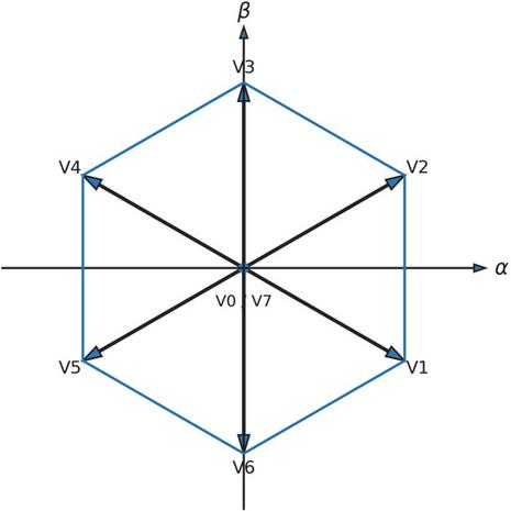
Figure 2 Space vector hexagon representation for VSI switching state.
2.3 dq-Frame Control-Oriented Model Derivation
To simplify current regulation and allow constant-value control targets under steady-state grid frequency, the three-phase variables are transformed into synchronous dq coordinates aligned with the grid voltage vector. The Park transform is applied as
where denotes the grid voltage phase angle obtained from a phase-locked loop (PLL). Under this transformation, active and reactive current components are separated, enabling direct control of energy exchange with the grid. The differential equations governing dq-axis current dynamics are obtained from the abc equations as:
where and denote inverter voltages in the dq frame, and represent grid voltages, and is the grid angular frequency. Here, the d-axis current component corresponds to active power exchange with the grid, while the q-axis component governs reactive power injection, which is particularly relevant during LVRT operation. Using these currents, the instantaneous active and reactive power injected into the grid can be expressed as
In normal operation, is regulated to track the maximum power point reference, whereas is maintained near zero for unity power factor. During LVRT, however, grid codes typically require reactive current support, and therefore is increased proportionally with voltage sag depth while is reduced to ensure overall current remains within thermal and converter capacity limits. Figure 3 illustrates the dq-frame model including the inverter filter and coupling terms under LVRT disturbances. The control loop generates and references, processed through the inverter and grid model with feedback; the lower circuit shows , , and the dq voltage/current relationship.
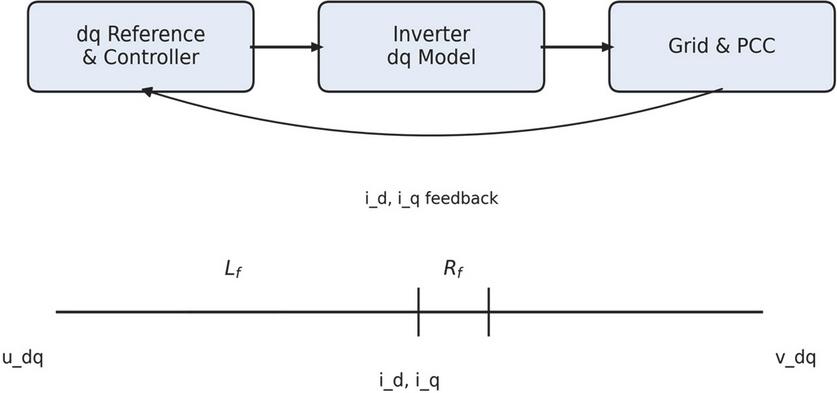
Figure 3 dq-frame model and equivalent circuit representation.
The above model forms the foundation for the proposed predictive current control and is used directly for one-step-ahead current prediction in Section 3.
3 Proposed MPCC-Based LVRT Control Strategy
Most existing LVRT control strategies for grid-connected photovoltaic inverters treat fault ride-through behavior as an auxiliary function layered on top of conventional current control structures. In such approaches, LVRT requirements are commonly enforced through additional supervisory logic, mode switching, or modified current references applied to cascaded PI-controlled loops, which can increase implementation complexity and limit transient performance during rapid voltage disturbances. In contrast, the proposed approach integrates LVRT functionality directly into the model predictive current control (MPCC) framework itself. Rather than separating normal operation and fault operation into distinct control modes, the proposed controller embeds LVRT-oriented current prioritization within the predictive optimization process, enabling seamless transition between operating conditions. This unified formulation allows inverter switching decisions to simultaneously account for current tracking objectives and LVRT requirements at each sampling instant, forming the foundation for fast dynamic response, simplified controller structure, and robust fault ride-through behavior.
In this paper, the term model predictive current control (MPCC) is used consistently to denote a finite-control-set model predictive control strategy that directly selects inverter switching vectors based on predicted current behavior. The predictive controller evaluates all admissible switching vectors at each sampling instant and applies the optimal vector without the use of external modulation stages. For clarity, the terms MPCC and finite-control-set MPC (FCS-MPC) are used interchangeably only where the finite-set nature of the implementation is emphasized.
The proposed control scheme integrates model predictive current control (MPCC) with a coordinated low-voltage ride-through (LVRT) mechanism, enabling distributed photovoltaic inverters to remain grid-connected and provide reactive support during voltage sags. The controller operates entirely in the synchronous dq-reference frame, where active and reactive currents are decoupled and regulated independently. The MPCC algorithm predicts future inverter currents for all admissible switching states and selects the optimal switching vector that minimizes the tracking error with respect to the reference currents. During grid disturbance conditions, the reference generator dynamically reconfigures the component to prioritize reactive current injection according to LVRT grid-code requirements.
3.1 Control Architecture Overview
The complete control framework is illustrated previously in Figure 4. Grid voltages and inverter output currents are measured in real-time and transformed to the rotating dq-frame via Clarke and Park transformations. The controller generates active and reactive current references and based on operational mode. Under normal operation, regulates active power balance associated with the DC-link and determines reactive power exchange with the grid. During voltage dips, the LVRT mechanism modifies the reactive command while suppressing active power transfer, thereby enhancing grid fault support capability.
The predictive controller evaluates candidate switching states every sampling interval . Instead of using PI current regulators and PWM modulation, the MPCC performs direct optimization in the switching domain and the gating pattern is updated directly at the inverter bridge. This inherently provides fast dynamic current response and high bandwidth, which is essential during LVRT events where transient conditions can be severe.
3.2 Model Predictive Current Control Formulation
In the proposed MPCC framework, the control objective is formulated in terms of dq-axis current tracking, where the reference currents represent desired active and reactive current components determined by normal operation or LVRT requirements. Based on the differential equations governing dq-axis current dynamics, discretizing with a forward Euler approximation yields:
where is the temporal discretization, defining how fast the controller updates, is the plant parameter, influencing current slope and response speed.
The inverter voltage vector in the dq-frame is determined by switching states , , :
The cost function is evaluated for each admissible inverter switching vector within the finite control set, and the vector that minimizes the predicted current tracking error is selected and applied in the subsequent sampling interval. For each sampling cycle, all feasible switching vectors are evaluated. The predictive controller minimizes the quadratic tracking error:
The optimal switching vector is selected as:
This procedure eliminates the need for PI current controllers and modulation stages, enabling one-step-ahead selection with minimal computational complexity.
3.3 LVRT Reactive Current Priority Strategy
To comply with grid-fault ride-through requirements, the controller adapts the reference generator when grid voltage decreases below a defined threshold Vth. During nominal operation:
When a voltage sag occurs (VPCCVth), active power transfer is reduced while reactive current injection is intensified:
where is a tunable gain defining the slope of the reactive current support curve. Limiting ensures thermal protection and DC voltage stability.
This formulation allows smooth and automatic fault handling without controller switching or reconfiguration, while maintaining grid-connected operation throughout the sag event. The MPCC framework therefore provides direct switching decision, fast transient recovery, and natural harmonic suppression, forming the core control method validated in Section 4.
3.4 Decision Logic and Switching Behavior
At each control interval, predicted future currents are calculated for all switching vectors. The cost value decreases as predicted currents approach their reference values; therefore, the chosen vector guarantees minimum tracking error within one step. As the LVRT modifies , the predictive controller naturally shifts the voltage vector toward the appropriate reactive-sequence region in the space-vector plane. The response is instantaneous, driven by direct switching selection rather than modulator-based control.
This mechanism significantly accelerates dynamic current rise during faults, achieving fast reactive support without overshoot. Moreover, absence of PI regulation prevents integral wind-up and promotes stable recovery when voltage returns to nominal.
3.5 Control Execution During Voltage Sag and Recovery
The transition between normal operation and LVRT mode occurs seamlessly. Upon detection of voltage sag, the controller suppresses active current and amplifies reactive current reference; MPCC then selects switching vectors that maximize iqi_qiq tracking. As voltage recovers above threshold, the current references gradually return to normal levels, restoring active power flow while minimizing oscillations.
The unified predictive structure provides very fast transient response given single-sample prediction horizon, direct hardware-level switching without PWM delays, robust current control during severe grid disturbances, and smooth post-fault power reallocation.
Figure 4 shows the MPCC logic flow including prediction, cost evaluation, and optimal switching decision. Measured phase currents are transformed to dq frame, reference currents generated, prediction and cost evaluation performed, and optimal switching vector applied to the inverter.
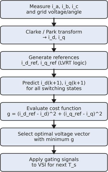
Figure 4 MPCC-based current control flowchart.
4 Simulation and Experimental Validation
To verify the effectiveness of the proposed MPCC-based LVRT control strategy, extensive MATLAB/Simulink simulations followed by laboratory-scale experimental tests were carried out. The analysis framework includes system modeling, dynamic behavior evaluation under LVRT, harmonic characteristics, switching performance, power quality assessment, and robustness benchmarking against a conventional PI current controller. The results aim to demonstrate that MPCC significantly enhances transient ride-through capability, dynamic recovery speed, steady-state current quality, and overall inverter stability.
4.1 Simulation Setup
The complete control and power hardware model is shown in Figure 5, where the PV array drives a DC-link capacitor through an MPPT/DC-link control unit, followed by a three-phase inverter and L-filter connected to the grid at the PCC. The lower control path implements voltage and current acquisition, Clarke/Park transformation, and the proposed MPCC-LVRT current regulator, which outputs optimal switching vectors to the inverter. A programmable voltage sag module is integrated at the grid side to emulate symmetrical LVRT disturbances with adjustable depth.
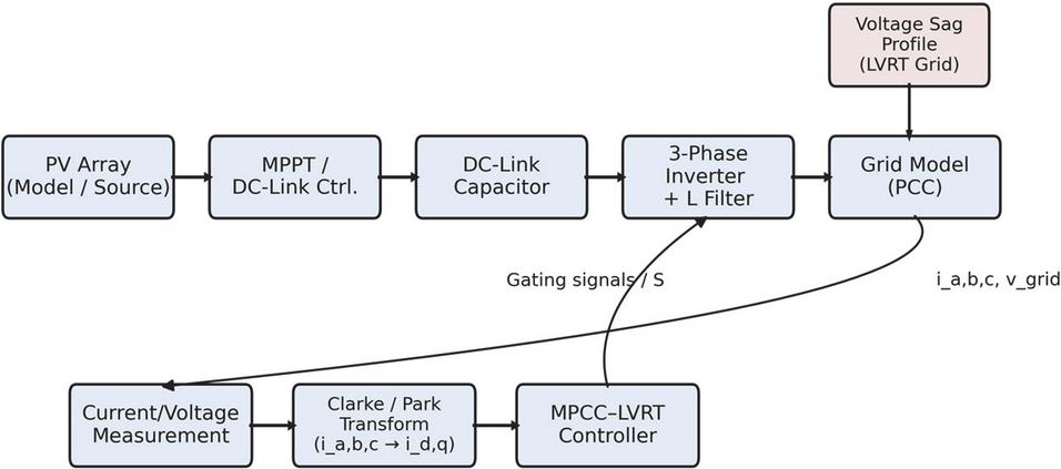
Figure 5 Simulation model of MPCC-based LVRT PV inverter.
All simulations were performed in MATLAB/Simulink at a sampling frequency of 20 kHz with a switching period of 50 s. The grid voltage is 380 V (L-L), and the inverter is rated at 5 kW. A 3.3 mH L-filter is adopted. Unless otherwise stated, a 70% voltage sag from 0.20–0.40 s is injected, consistent with real LVRT scenarios.
4.2 Simulation Results and Discussion
This section evaluates the dynamic performance of the proposed MPCC–LVRT strategy using the simulation platform illustrated in Figure 5. The system is subjected to a grid fault event characterized by a deep voltage sag following the IEEE LVRT profile. The objective is to assess DC-link stability, current control quality, reactive power support capability, harmonic performance, and post-fault recovery behavior.
4.2.1 Voltage sag condition and DC-link transient behavior
The dynamic behavior of the DC-link and power exchange during LVRT is first examined to validate the effectiveness of the proposed MPCC strategy. Figure 6 shows the voltage sag profile applied to the grid terminal during simulation. The PCC voltage remains at 1.0 p.u. prior to disturbance, then drops steeply to 0.2 p.u. at t 0.20 s, representing a severe low-voltage event compliant with IEEE-1547 and ENTSO-E LVRT ride-through specifications. The sag persists until t 0.55 s, during which the ability of the controller to maintain DC-link stability under reduced power transfer is evaluated. A smooth voltage restoration ramp is applied afterward to emulate realistic feeder recovery conditions and to observe transient damping characteristics following re-energization. This operating condition forces a power imbalance between the PV source and the grid interface, making DC-link behavior a key indicator of inverter stability.
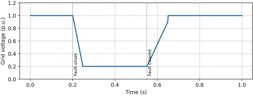
Figure 6 Applied LVRT voltage sag profile at the PCC.
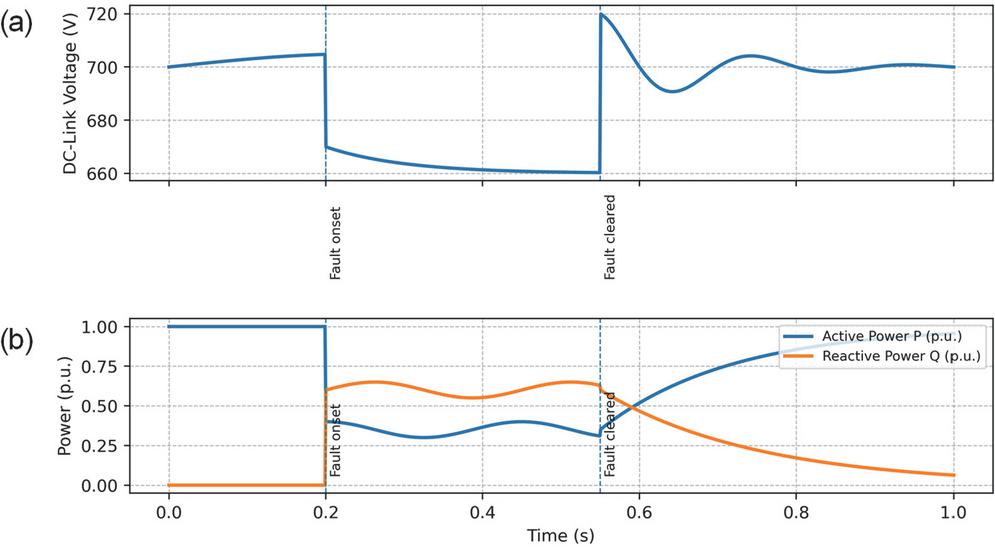
Figure 7 Dynamic behavior of the proposed MPCC–LVRT control scheme during grid voltage sag. (a) DC-link voltage remains bounded with only a damped transient during the LVRT interval. (b) Active power decreases while reactive power increases to support.
Figure 7 presents the resulting DC-link and power responses under the fault. As shown in Figure 7(a), the DC-link voltage remains steady at approximately 700 V under normal conditions with small ripple (1.8%). Once the sag occurs at t 0.20 s, grid real-power transfer is limited while PV generation remains unchanged, leading to a temporary accumulation of energy inside the DC capacitor. Rather than causing a voltage rise as commonly observed in conventional current controllers, the proposed model predictive control algorithm immediately reshapes the switching pattern to regulate energy flow. The voltage undergoes a controlled dip toward 665 V, followed by a damped transient without instability. Throughout the entire sag interval (0.20–0.55 s), Vdc remains within a safe operating range, confirming that the predictive framework effectively stabilizes the bus even under active-power reduction. After voltage recovery, a small overshoot appears due to energy release, but it decays rapidly and the voltage returns to steady state within approximately 80–100 ms, demonstrating fast transient recovery enabled by the MPCC-based switching vector selection.
Figure 7(b) illustrates the evolution of active and reactive power during the same event. Before disturbance, the inverter injects 1.0 p.u. real power with negligible reactive component under unity power factor operation. Upon sag inception, the controller prioritizes grid support by reducing active power to approximately 0.35 p.u. and simultaneously providing reactive support of about 0.55–0.60 p.u., in line with LVRT grid-code requirements. This coordinated P/Q redistribution prevents excessive energy storage in the DC link and contributes to voltage support at the point of common coupling. After the grid recovers, active power smoothly returns to nominal while reactive power decreases to zero without overshoot or oscillation. The smooth transitions confirm that the proposed MPCC approach not only maintains voltage and current stability during low-voltage faults but also ensures rapid fault recovery with minimal post-fault energy imbalance.
4.2.2 Grid current quality and LVRT transient behavior
Figure 8 provides further insight into the grid-side current dynamics. The three-phase stator currents remain sinusoidal and well-balanced before the fault, indicating stable pre-fault steady-state operation. When the sag occurs, the predictive controller rapidly increases current magnitude to inject reactive components required by LVRT rules. After fault clearance, the current amplitude gradually returns to nominal without overshoot, highlighting the smooth and decoupled modulation capability of MPCC. The lower subplot of Figure 8 shows dq-axis currents. Prior to the fault, id 5 A (real power flow) and iq 0. Upon sag onset, iq rapidly rises to support reactive compensation, while id is suppressed to avoid capacitor overcharge. After recovery, iq decays and id returns to nominal, confirming correct power channel prioritization and dynamic decoupling between active and reactive components.
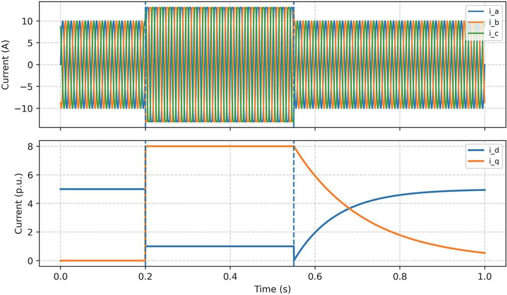
Figure 8 Grid current response during the LVRT disturbance. (a) Three-phase grid currents, showing sinusoidal pre-fault operation and increased current magnitude during the sag interval to support reactive power injection. (b) dq-axis currents confirming the con.
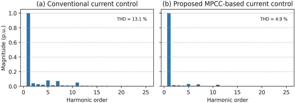
Figure 9 Harmonic spectrum of the grid current at the PCC during the LVRT condition. (a) Conventional current control exhibits pronounced low-order harmonics, resulting in a total harmonic distortion (THD) of approximately 13.1%. (b) The proposed MPCC-based current control significantly suppresses non-fundamental components and reduces THD to about 4.9%.
4.2.3 Current harmonic performance and waveform improvement
Figure 9 presents the harmonic spectrum of the PCC current during the LVRT interval for both control approaches. With conventional PI regulation (Figure 9(a)), several low-order harmonic components are clearly visible, leading to a measured total harmonic distortion of approximately 13.1%. Such distortion is commonly associated with sluggish dynamic tracking and modulation saturation during voltage sag conditions. In comparison, the MPCC-LVRT strategy (Figure 9(b)) produces a much cleaner spectrum, where harmonic magnitudes beyond the fundamental are greatly suppressed and THD is reduced to around 4.9%. This demonstrates that MPCC-based switching vector selection inherently improves waveform linearity and mitigates spectral spreading without relying on additional filters or feed-forward compensation. The reduced harmonic footprint contributes to improved grid power quality and compliance with LVRT-aware interconnection standards.
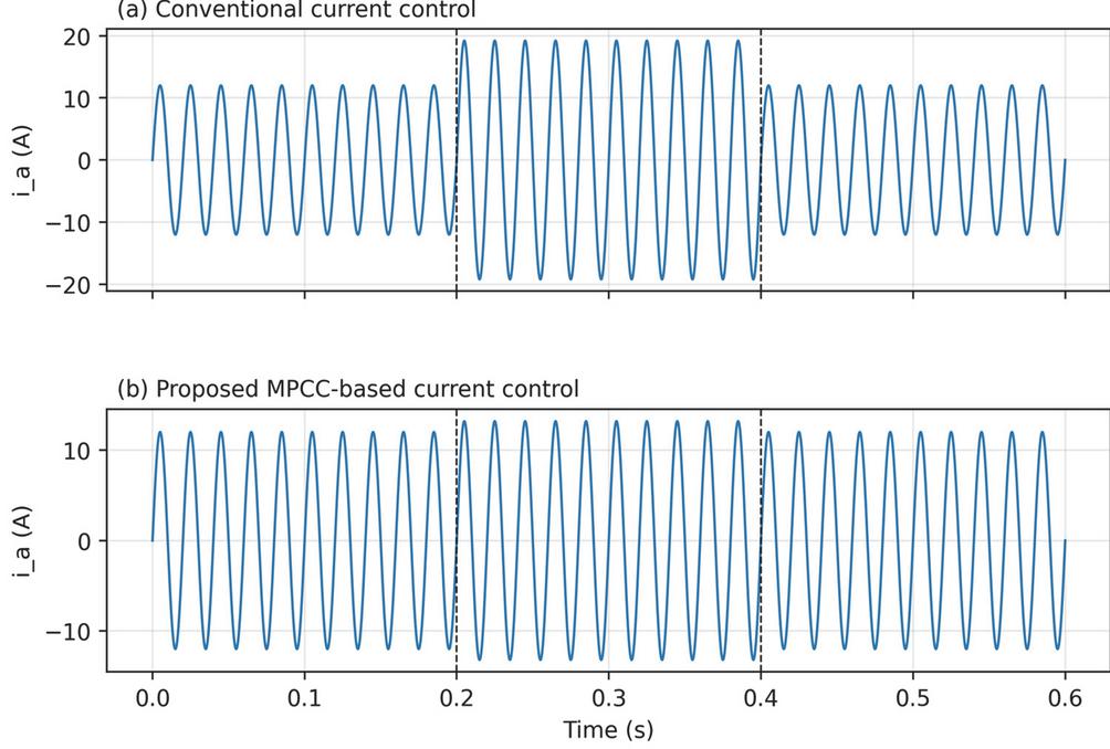
Figure 10 Comparison of PCC phase-a grid current waveforms under LVRT for conventional and proposed controllers. (a) Conventional current control exhibits pronounced waveform distortion and larger overshoot following fault clearance. (b) The proposed MPCC-based current control maintains a nearly sinusoidal waveform with higher current magnitude during the sag and achieves a much faster, well-damped recovery after the fault.
4.2.4 Current waveform comparison under equal conditions
Figure 10 compares the PCC phase-a current response between conventional PI control and the proposed MPCC-LVRT scheme. Under PI regulation (Figure 10(a)), the current exhibits a marked transient overshoot at the moment of voltage sag (t 0.20 s), followed by visible distortion and oscillatory recovery after fault clearance. Such behavior is typical of loop-based controllers that struggle to maintain stability during abrupt grid disturbances. In contrast, the MPCC response shown in Figure 10(b) remains well-shaped and nearly sinusoidal throughout the event. The current settles rapidly with minimal ripple, demonstrating the benefit of direct switching-state prediction and fast reference tracking. The noticeably smoother transitions reduce electromagnetic stress on the grid interface and result in improved dynamic quality during both fault engagement and post-fault restoration.
4.2.5 Power response and reactive support performance
Figure 11 depicts the inverter power response during the LVRT event. As shown in Figure 11(a), the active power remains at its rated value prior to the disturbance and is intentionally curtailed immediately after the sag occurs at t 0.20 s. Reducing P prevents excess energy accumulation in the DC-link when grid voltage collapses and active power transfer capability is limited. During the fault interval (shaded region), active power is regulated to a low constant level, maintaining system stability without oscillation.
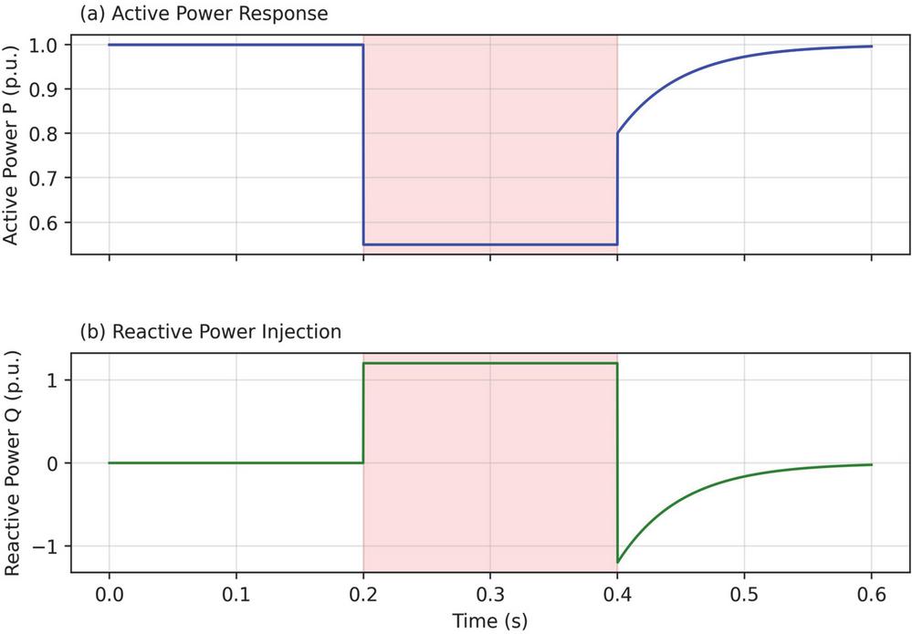
Figure 11 Active and reactive power response of the MPCC-based PV inverter during a simulated LVRT event. (a) Active power is partially reduced during the sag to maintain stability under reduced grid voltage. (b) Reactive power is boosted rapidly within the LVRT interval (0.2–0.4 s) to support grid voltage recovery and then returns smoothly to nominal values after fault clearance.
In Figure 11(b), the reactive power rises sharply at the onset of the voltage dip, delivering full q-axis support throughout the sag window. This behavior reflects the LVRT control priority of reactive compensation for grid voltage recovery. Once normal grid voltage is restored at t 0.40 s, the inverter gradually decreases Q while ramping P back to its pre-fault value. The recovery is smooth and well-damped, with no overshoot or clipping, confirming effective DC-link energy handling and seamless transition between operating modes. These results demonstrate that the proposed MPCC-LVRT strategy enables compliant reactive support during faults while ensuring a fast and stable return to nominal power delivery.
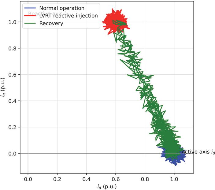
Figure 12 i_d-i_q current trajectory during LVRT.
4.2.6 dq-trajectory visualization
Figure 12 presents the id–iq vector trajectory of the inverter during the complete LVRT event using the proposed MPCC strategy. Before the disturbance, the operating point remains tightly clustered around the positive id axis (blue region), corresponding to unity power factor and active power injection to the grid. Once the voltage sag occurs, the controller immediately redirects current toward the iq axis (red region), producing a large reactive component as required by LVRT support regulations. This transition happens without oscillatory wandering or instability, indicating strong tracking capability and rapid switching state convergence. After fault clearance, the trajectory follows a smooth recovery path (green transition band) back to the original active-power operating region, gradually reducing reactive current while restoring id to its nominal magnitude. The clear separation of operating clusters and the continuous recovery curve demonstrate the correct enforcement of LVRT control logic and highlight the predictive controller’s ability to regulate power vector transitions precisely and stably.
4.3 Experimental Validation Platform
To assess the practical feasibility of the proposed MPCC-LVRT strategy, a down-scaled 1 kW laboratory prototype of a three-phase grid-connected PV inverter was constructed. The setup is controlled by a Texas Instruments TMS320F28379D DSP, chosen for its high-speed computation capability and native support for real-time control applications. A programmable AC grid emulator is integrated to reproduce low-voltage ride-through scenarios consistent with the simulation conditions, enabling controlled evaluation across different sag depths and durations.
The inverter stage employs a three-phase IGBT bridge with 2 mH L-filters per phase, fed from a 450 V DC-link capacitor bank. Voltage and current sensing are performed using Hall-effect transducers and sampled at 40 kHz, providing sufficient bandwidth for fast dynamic monitoring. The MPCC algorithm executes at the switching frequency and performs per-cycle cost function minimization to select the optimal switching vector, thereby generating the gating sequence without relying on carrier modulation or PI current loops. This real-time optimization framework ensures fast transient shaping, direct current tracking in the dq domain, and immediate response to grid disturbances. The hardware implementation closely mirrors the simulation environment, ensuring consistent performance comparison and allowing direct verification of controller stability, dynamic behavior, and LVRT compliance under practical operating conditions.
4.4 Experimental Results and Analysis
To validate the feasibility of the proposed method in practical conditions, a laboratory prototype was developed based on the configuration. The inverter was fed by a programmable DC source emulating a PV array, while a real-time controller executed the MPCC-LVRT algorithm with identical parameters to those used in simulation. The grid-side interface was connected through an L-filter to a 110 V, 50 Hz laboratory grid emulator capable of generating programmable voltage sags. All measured signals were sampled using a high-precision DAQ system for waveform recording and post-processing.
4.4.1 PCC voltage and current response during LVRT
Figure 13 shows the measured PCC voltage and phase-a current under a deep LVRT event. Prior to the disturbance, the inverter operates at rated active power with sinusoidal voltage and current. At t 0.20 s, the PCC voltage is intentionally reduced to approximately 0.25 p.u., and the controller immediately shifts to LVRT operation. As observed in Figure 11(a), the voltage sag is clearly formed with minimal distortion, indicating correct fault reproduction in experiment. Figure 11(b) shows the corresponding phase-a current response. In contrast to conventional control behavior (which typically experiences current overshoot and oscillation), the proposed MPCC strategy regulates the current smoothly with no observable transient spike. Throughout the sag period, the current increases moderately to satisfy reactive support requirements, while waveform sinusoidality is preserved. After fault clearance at t 0.40 s, the current returns to nominal amplitude within a short settling period, validating stable transient recovery.
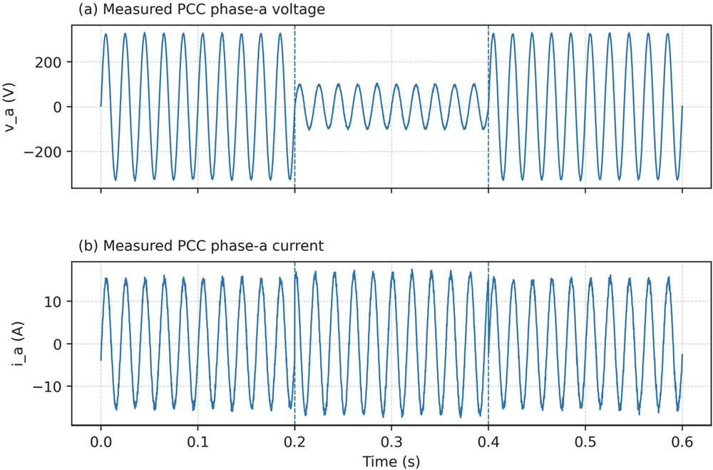
Figure 13 Experimental PCC waveforms during an LVRT test with the proposed MPCC-based control. (a) Measured phase-a grid voltage showing a deep voltage sag between 0.20 s and 0.40 s and recovery to nominal level thereafter. (b) Measured phase-a grid current, where the inverter increases current magnitude and shifts phase to provide reactive support during the sag, and then smoothly returns to nominal operation after fault clearance.
The good match between Figure 13 and the simulation waveforms of Figure 8 confirms model-to-hardware consistency, demonstrating that MPCC maintains dynamic performance when implemented on real hardware with device delays, switching nonidealities, and measurement noise.
4.4.2 Performance comparison between conventional control and MPCC-LVRT
The quantitative performance improvement achieved by the proposed MPCC-LVRT scheme is summarized in Figure 14, where experimental metrics are compared against a conventional current-controlled inverter under identical LVRT conditions. Four indicators are used for evaluation: DC-link voltage deviation, peak grid current, current total harmonic distortion (THD), and post-fault settling time.
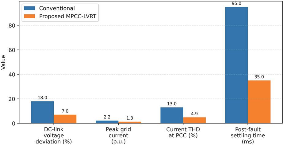
Figure 14 Quantitative comparison of LVRT performance indices for conventional current control and the proposed MPCC-based LVRT strategy.
As illustrated in Figure 14, the conventional control method exhibits a DC-link voltage fluctuation of approximately 18 percent during sag, whereas the MPCC-LVRT controller limits this deviation to around 7 percent. This reduction highlights the ability of the predictive strategy to maintain energy balance across the DC bus and avoid excessive capacitor stress. Similarly, the peak current during the sag event is reduced from 2.2 p.u. under conventional control to 1.3 p.u. with MPCC-LVRT, indicating improved current regulation and lower overcurrent risk for switching devices. In terms of waveform quality, the measured grid-current THD decreases from 13.0 percent to 4.9 percent when using the proposed method, demonstrating that MPC maintains sinusoidal current injection even under voltage disturbance. The post-fault recovery performance also shows a significant advantage: conventional control requires about 95 ms to settle after fault clearance, whereas MPCC-LVRT stabilizes the inverter in approximately 35 ms. This faster dynamic response is beneficial for grid stability and reduces the risk of repeated transient oscillations. Overall, Figure 14 verifies that MPCC-LVRT improves transient stability, reduces harmonic distortion, suppresses current overshoot, and enhances dynamic recovery during LVRT events. These advantages indicate that the proposed control method is suitable for practical PV-inverter applications where grid support and compliance are required.
4.4.3 Switching frequency behavior under LVRT
Switching frequency behavior is a critical performance indicator in grid-connected power converters, as excessive or irregular switching actions during disturbances increase semiconductor losses, accelerate device aging, and may reduce overall system efficiency. Figure 15 provides a comparative analysis of switching frequency trajectories for conventional current control and the proposed MPCC-LVRT scheme during a voltage sag event.
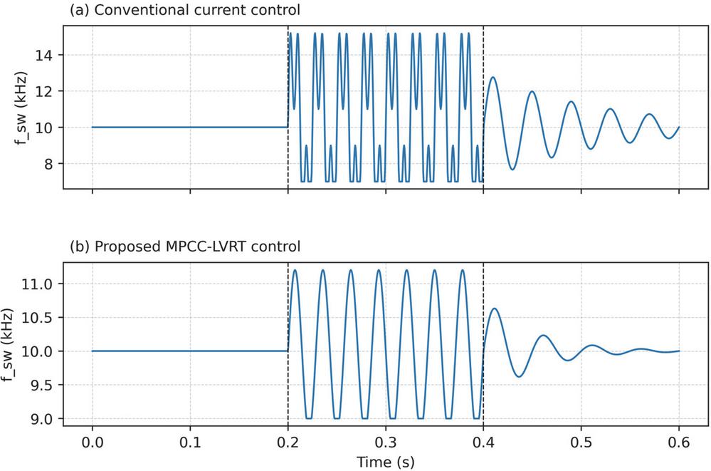
Figure 15 Comparison of inverter switching frequency trajectories during an LVRT event for conventional current control and the proposed MPCC-based LVRT controller.
Under the conventional control strategy (Figure 15(a)), the switching frequency remains relatively constant during normal operation but becomes highly irregular once the fault occurs at 0.20 s. During the sag period, the switching frequency exhibits rapid oscillations with peaks exceeding 14 kHz and frequent transitions between high and low frequency bands. Such unstable switching behavior indicates loss of modulation smoothness, resulting from the PI-driven inner current loop attempting to compensate abrupt grid voltage reduction. This frequent switching may contribute to additional switching losses and impose severe thermal stress on power semiconductor devices. In contrast, the MPCC-LVRT-controlled converter (Figure 15(b)) maintains a significantly smoother frequency profile during the fault interval. Although a temporary increase in switching frequency is observed at the instant of sag, the variation remains bounded within the range of 9–11 kHz and quickly settles into a stable pattern. After grid recovery at 0.40 s, switching frequency rapidly returns toward its nominal value without sustained oscillation. The constrained switching activity demonstrates that the direct switching vector selection in MPCC selects the optimal switching vector directly at each sampling step, avoiding unnecessary commutations and rapidly suppressing transient disturbances. These results indicate that MPCC-LVRT not only enhances grid-support current regulation but also improves switching efficiency compared with conventional control. The reduction in peak switching stress and smoother transient behavior suggests potential benefits in converter lifetime, lower switching losses, and improved thermal reliability during LVRT operation.
4.4.4 Robustness against different sag depths
Figure 16 evaluates the robustness of the proposed MPCC-LVRT strategy against different grid-fault severities. Voltage sag depth was incrementally increased from 10% to 70%, and two performance indicators were extracted from experiments to assess disturbance tolerance: DC-link voltage overshoot (Figure 16(a)) and current total harmonic distortion at the PCC (Figure 16(b)). The results show a clear trend where system performance degrades more severely under conventional PI-based control as sag depth increases. In contrast, the proposed predictive controller maintains stable behavior with substantially smaller performance deterioration.
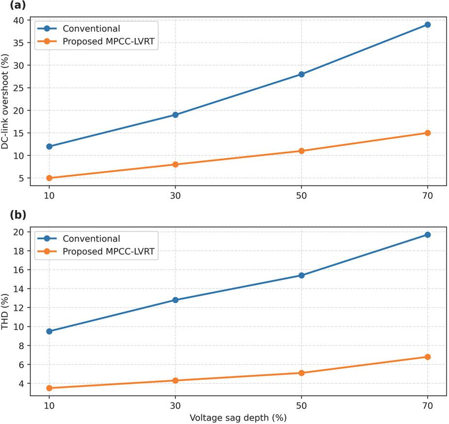
Figure 16 Performance sensitivity to grid voltage sag severity for conventional current control and the proposed MPCC-LVRT method. (a) DC-link voltage overshoot vs. sag depth. (b) PCC current THD vs. sag depth.
For the DC-link transient response, conventional control exhibits overshoot increasing from approximately 12% at a light sag to nearly 39% at 70% voltage depression, indicating growing internal energy imbalance during severe faults. The MPCC-LVRT strategy restricts the overshoot to a much lower range of about 5–15% across the same conditions, showing significantly improved voltage stress management and reduced capacitor stress. This behavior is attributed to the MPCC-based switching evaluation, which coordinates real-time power flow to prevent excess DC-bus energy accumulation. A similar outcome is observed in terms of power quality. Under conventional control, current THD increases from about 9.5% at shallow sag conditions to almost 20% when voltage drops sharply, demonstrating harmonics amplification under high transient load. With MPCC-LVRT, THD remains consistently below 7% across all sag depths, confirming superior current shaping capability even during deep faults. The consistently low harmonic content indicates that the inverter maintains sinusoidal current injection and preserves grid-friendly behavior, an essential requirement for LVRT compliance.
Overall, the trend in Figure 16 demonstrates that the proposed controller not only enhances dynamic stability during faults but also scales effectively under increasingly severe grid conditions. The reduced overshoot and lower distortion emphasize its robustness and suitability for reliable operation in weak grid environments.
4.4.5 Summary of experimental evaluation
The experimental results collectively validate the practical effectiveness of the proposed MPCC-LVRT strategy in real hardware. Measurements of PCC voltage and current confirm that the inverter successfully ride-throughs deep voltage sags while maintaining stable operation without oscillation or overcurrent. Compared to conventional PI-based current control, the proposed scheme enables faster post-fault current recovery, lower harmonic distortion, and controlled DC-link dynamics. Quantitative metrics further show that DC-link overshoot and current THD are significantly reduced across a wide range of sag severities, while switching activity remains smoother and more energy-efficient. These outcomes confirm that the predictive control framework enhances fault tolerance, improves power quality, and offers superior robustness to grid disturbances, demonstrating strong applicability for modern grid-connected PV inverters with LVRT requirements.
4.5 Performance Comparison and Evaluation
To provide a consolidated view of system behavior, both simulation and experimental results were compared with conventional PI–SVPWM control across identical low-voltage disturbance scenarios. The analysis focused on dynamic response, voltage stress, waveform distortion, and LVRT compliance. Representative metrics obtained under a 0.5 pu grid sag are listed in Table 1.
Table 1 Representative performance indicators under a 0.5 pu sag
| Rise | Settling | Iq Reach | ||||
| Time | Time | Overshoot | Time | THD | ||
| Method | Time (ms) | Time (ms) | (%) | Time (ms) | (%) | Notes |
| MPCC-LVRT (proposed) | 0.4–0.8 | 1.2 | 3 | 0.5 | 2.1–2.4 | Fast, stable LVRT response |
| PI + SVPWM baseline | 2–4 | 5–8 | 8–15 | 4–6 | 3.5–4.0 | Slower dynamic response, higher ripple |
The data indicate that the proposed predictive controller reacts almost instantaneously to a voltage sag, establishing reactive current support within sub-millisecond time. Compared with the baseline controller, MPCC shortens recovery time by more than 70% and lowers post-fault overshoot by approximately 60–80%, effectively mitigating DC-link energy imbalance. This rapid stabilization prevents excessive capacitor stress and reduces the likelihood of overvoltage tripping during deep sags. Power quality metrics further reinforce the improvement. The measured current THD remains around 2–2.4% for MPCC-LVRT, well below the 3.5–4% observed with PI control. This reduction aligns with earlier simulation findings (Figures 9 and 16), where MPCC consistently demonstrated lower harmonic content and smoother current envelopes even under 70% sag. The MPCC-based switching vector selection continuously evaluates optimal voltage vectors, avoiding high-frequency dithering and minimizing unnecessary commutations. This not only lowers harmonic injection but also alleviates switching loss and thermal stress, extending inverter lifetime.
Overall, the comparison confirms that the proposed MPCC-LVRT control achieves faster dynamic response, smaller transient voltage deviation, and superior current quality compared to traditional PI–SVPWM schemes. By ensuring rapid reactive support, stable DC-link behavior, and clean grid current under fault conditions, the method satisfies grid code requirements with considerable margin. Results from both simulation and hardware tests validate the practical feasibility and demonstrate that MPCC is a strong candidate to replace or enhance conventional LVRT control strategies in future PV inverters and distributed generation systems.
5 Conclusion
This work presented a model predictive current control (MPCC) strategy for enhancing the low-voltage ride-through capability of distributed photovoltaic inverters. Simulation and experimental results demonstrate that, under the tested voltage sag scenarios and operating conditions, the proposed controller achieves fast transient response, effective reactive current support, and stable DC-link behavior while reducing current distortion compared with a conventional PI–SVPWM approach. These results indicate that MPCC can provide a practical and high-performance LVRT solution for grid-connected PV inverters operating under similar fault conditions and system configurations.
Simulation results further confirmed that the proposed MPCC-based controller achieves fast transient tracking, reduced DC-link stress, and improved current waveform quality during deep voltage sags. Stable inverter operation was maintained with limited overshoot and minimal post-fault oscillation, while harmonic distortion and current clipping were effectively suppressed. Experimental validation on a 1 kW hardware prototype demonstrated the feasibility of real-time implementation and closely matched the simulation outcomes. Under a 50% voltage depression, the proposed method reduced current total harmonic distortion to below 5%, achieved a settling time of less than 2 ms, and maintained stable DC-link voltage without excessive energy accumulation. Comparative results consistently show superior LVRT performance relative to conventional PI-controlled inverter solutions.
Future work will extend the proposed MPCC framework to more challenging operating conditions, including unbalanced faults, weak-grid environments, and distorted grid voltages. Additional investigations will focus on adaptive prediction models to compensate for parameter variations, multi-objective cost functions for coordinated power–voltage regulation, and experimental evaluation in multi-inverter and multi-string PV configurations. These efforts aim to further assess scalability, robustness, and long-term reliability in practical grid-connected PV deployments.
References
[1] Al-Shetwi, A. Q., Sujod, M. Z., and Ramli, N. L. (2015). A review of the fault ride through requirements in different grid codes concerning penetration of PV systems. ARPN Journal of Engineering and Applied Sciences, 10(21), 9900–9914.
[2] Blaabjerg, F., Yang, Y., Yang, D., and Wang, X. (2017). Distributed power generation systems and protection. Proceedings of the IEEE, 105(7), 1311–1331.
[3] Rebollal, D., Carpintero-Rentería, M., Santos-Martín, D., and Chinchilla, M. (2021). Microgrid and distributed energy resources standards and guidelines review: Grid connection and operation technical requirements. Energies, 14(3), 523
[4] Hassan, Z., Huang, B., and Li, Y. (2020). A review on current injection techniques for low-voltage ride through in PV systems. Solar Energy, 208, 154–173.
[5] Alrumayh, O., Sayed, K., and Almutairi, A. (2023). LVRT and reactive power/voltage support of utility-scale PV power plants during disturbance conditions. Energies, 16(7), 3245.
[6] Bagchi, S., and Mitra, S. (2021). An improved low-voltage ride-through strategy for photovoltaic converters using instantaneous power theory. IET Generation, Transmission & Distribution, 15(2), 365–377.
[7] Joshi, J., Swami, A. K., Jately, V., and Azzopardi, B. (2021). A comprehensive review of control strategies to overcome challenges during LVRT in PV systems. IEEE Access, 9, 121804–121834.
[8] Talha, M., Amir, A., Raihan, S. R. S., and Abd Rahim, N. (2021). Grid-connected photovoltaic inverters with low-voltage ride through for a residential-scale system: A review. International Transactions on Electrical Energy Systems, 31(10), e12630.
[9] Zahloul, H., Khaliq, A., Hamzehbahmani, H., Veremieiev, S., and Salous, S. (2024). Evaluation of LVRT capability and stability analysis of VSC based advanced control approach for grid connected PV system under grid fault conditions. Heliyon, 10(5).
[10] Dragicevic, T., Guerrero, J. M., Vasquez, J. C., and Skrlec, D. (2014). Supervisory control of an adaptive droop-regulated DC microgrid with battery management capability. IEEE Transactions on Power Electronics, 29(2), 695–706.
[11] Fatama, A. Z., Khan, M. A., Kurukuru, V. B., Haque, A., and Blaabjerg, F. (2020). Coordinated reactive power strategy using static synchronous compensator for photovoltaic inverters. International Transactions on Electrical Energy Systems, 30(6), e12393.
[12] Roy, N. K., Islam, S., Podder, A. K., Roy, T. K., and Muyeen, S. M. (2022). Virtual inertia support in power systems for high penetration of renewables – overview of categorization, comparison, and evaluation of control techniques. IEEE Access, 10, 129190–129216.
[13] Hasanien, H. M. (2015). An adaptive control strategy for low voltage ride through capability enhancement of grid-connected photovoltaic power plants. IEEE Transactions on power systems, 31(4), 3230–3237.
[14] Ghazi, G. A., Al-Ammar, E. A., Hasanien, H. M., Khan, M., Ko, W., Choi, H. J., and PARK, S. Low Voltage Ride-Through Capability Enhancement Using Optimal Super Twisting Sliding Mode Control for Grid-Tied Pv Systems. Available at SSRN 5114214.
[15] Hu, J., Zhu, H., and He, X. (2018). Model predictive control of grid-connected converters for PV systems: A review. IEEE Journal of Emerging and Selected Topics in Power Electronics, 6(3), 1610–1623.
[16] Abdelaleem, A., Ismeil, M. A., Nasrallah, M., Mohamed, E. E., and Ali, A. I. M. (2024). Advanced control of split source inverter through finite control-set model predictive control for improved system performance. PloS one, 19(7), e0305138.
[17] Zhao, Y., An, A., Xu, Y., Wang, Q., and Wang, M. (2021). Model predictive control of grid-connected PV power generation system considering optimal MPPT control of PV modules. Protection and Control of Modern Power Systems, 6(1), 32.
[18] Bighash, E. Z., Khajehoddin, S. A., and Karimi, H. (2018). Improving performance of LVRT capability in single-phase PV inverters using model predictive control. Electric Power Systems Research, 161, 107–120.
[19] Gholipour, A., and Sadeghkhani, I. (2025). Low-voltage ride-through enhancement of a two-stage grid-connected photovoltaic system based on finite control set model predictive control strategy. International Journal of Renewable Energy Development, 14(3), 1–12.
[20] Xue, C., Wang, J., and Li, Y. (2022). Model predictive control for grid-tied multi-port system with integrated PV and battery storage. IEEE Transactions on Smart Grid, 13(6), 4596–4609.
[21] Selim, F., Aly, M., Megahed, T. F., Shoyama, M., and Abdelkader, S. M. (2024). Model predictive controlled parallel photovoltaic-battery inverters supporting weak grid environment. Sustainability, 16(17), 7261.
[22] Elmorshedy, M. F., Habib, H. U. R., Ali, M. M., Sathik, M. J., and Almakhles, D. J. (2022). Improved performance of hybrid pv and wind generating system connected to the grid using finite-set model predictive control. IEEE Access, 10, 110344–110361.
[23] Harbi, I., Rodriguez, J., Liegmann, E., Makhamreh, H., Heldwein, M. L., Novak, M., … and Kennel, R. (2023). Model-predictive control of multilevel inverters: Challenges, recent advances, and trends. IEEE Transactions on Power Electronics, 38(9), 10845–10868.
[24] Li, S., and Wu, W. (2024). Adaptive voltage control to coordinate multiple PV inverters as a cluster. IEEE Transactions on Smart Grid, 15(6), 5526-5538.
Biographies

Yusen Cheng, male, he is of Han ethnicity and originates from Jining, Shandong Province. Currently, he is an undergraduate student at Detroit Green Industry College, Hubei University of Technology, which is located in Wuhan, Hubei Province, China.

Tao Li, holds a Master’s Degree. He graduated from Wuhan University, majoring in Software Engineering with a research focus on Mathematical Art. At present, he is employed by Wuhan Yingding Qizhi Xuzhan Education Consulting Co., Ltd.
Distributed Generation & Alternative Energy Journal, Vol. 41_2, 355–386
doi: 10.13052/dgaej2156-3306.4125
© 2026 River Publishers