A New Controller Design for Eliminating the Negative Impedance Increase Effect Caused by Constant Power Loads in DC Microgrids
Anjiang Liu1,*, Shuqing Hao1, Yue Li1, Yu Miao1 and Hongyu Zuo2
1Electric Power Research Institute, Guizhou Power Grid Co., Ltd, Guiyang, Guizhou, China
2Zunyi Power Supply Bureau of Guizhou Power Grid Company, Zunyi, Guizhou, China
E-mail: anjiang5615@outlook.com; rty123489@163.com; leeli@hust.edu.cn; gl127390@163.com; Wd21588@126.com; hq8899772@163.com; hcd121588@163.com
*Corresponding Author
Received 28 January 2026; Accepted 14 July 2026
Abstract
The growing use of power electronic loads in DC microgrids has turned out to be a significant source of stability challenges, mainly due to the detrimental increased impedance behaviour of Constant Power Loads (CPLs) that can cause the danger of especially high and low DC bus voltage fluctuations and even voltage collapse. The proposed control strategy is based on a continuous-time Model Predictive Control (MPC) approach. A Disturbance Observer (DOB) is integrated to enhance robustness. This combination effectively mitigates the negative incremental impedance effect caused by constant power loads (CPLs) and improves DC bus voltage stability. A detailed nonlinear model of a solar Photovoltaic (PV)-battery-based DC microgrid providing power for a CPL is constructed, and the unstable condition is analytically expressed. Simulation results reveal that, during open-loop operation, the voltage at the DC bus drops from 400 V to around 265 V with a voltage deviation of nearly 135 V and a negative incremental impedance of approximately 27 , which indicates a voltage collapse tendency. The DC bus voltage goes back to its reference value with virtually no steady-state error, smaller overshoot, and faster settling time, all while voltage oscillations are effectively suppressed when the MPC-DOB controller is in place. The comparative results also indicate better damping, smoother control current profiles, and improved robustness against sudden changes of the CPL power, which altogether prove that the proposed control strategy has a very positive impact on the stability of DC microgrid operation.
Keywords: Constant power load, DC microgrid stability, model predictive control, disturbance observer, negative incremental impedance.
1 Introduction
The rapid rise in the use of renewable energy sources, along with energy storage systems plus power electronic converters, has been a determining factor in the uptake of DC microgrids in contemporary electric networks [1]. DC microgrids on their own have many advantages over traditional AC systems in terms of efficiency, control architecture, and compatibility with distributed generation and energy storage units, respectively [2]. Nonetheless, the introduction of a large number of power electronic loads with very strict regulations has created problems regarding stability [3]. In this respect, constant power loads, which are extensively utilized in data centres, electric vehicles, and telecommunication systems, are significantly changing the dynamic behaviour of DC microgrids and therefore demand advanced control strategies for reliable operation [4].
A significant contributor to the instability of DC microgrids is the negative incremental impedance property of CPLs [5]. CPLs, in contrast to passive loads, keep drawing the same amount of power no matter the voltage variations, causing the input current to become larger when the bus voltage drops [6]. This inverse current-voltage relationship brings about a negative impedance effect, which lessens the system damping and causes voltage oscillations to be stronger [7]. The coupling of power electronic converters with CPLs, along with the unpredictability of renewable generation and load, makes the instability even worse and, if not dealt with correctly, may lead to voltage collapse [8].
A variety of control and stabilization methods have been suggested to counteract the instability caused by current-controlled power loads in DC microgrids [9]. The traditional methods consist of droop control, virtual impedance techniques, passivity-based control, and cascaded proportional-integral (PI) controllers [10]. All these methods would increase stability, but only under specific, limited conditions, and their performance would decline with large disturbances, parameter uncertainties, and fast load variations [11]. Besides, many of the current approaches work with linearized models or require tuning, which significantly reduces their robustness and efficacy in controlling the negative impedance increase effect introduced by current-controlled power loads [12].
These existing control strategies exhibit several limitations under practical operating conditions. Methods such as droop control, PI, sliding mode, and RST approaches often suffer from reduced performance under large disturbances, require precise tuning, or depend heavily on accurate system modelling. In addition, their reliance on linearized models limits their effectiveness in handling nonlinearities introduced by constant power loads, thereby necessitating a more robust and adaptive control strategy.
Conventional control strategies such as droop, PI, sliding mode, and RST approaches rely on precise tuning and accurate system models, with performance largely based on linearized representations. Under dynamic operating conditions, especially in the presence of nonlinearities introduced by constant power loads, their adaptability and effectiveness can be constrained, motivating the need for more robust and adaptive control strategies.
To overcome the research proposes a novel controller design to get rid of the CPL-induced instability caused by constant power loads in DC microgrids, which is one of the major drawbacks of the current control strategies [13]. It employs a continuous-time model predictive control scheme combined with a disturbance observer [14]. The nonlinearities caused by CPL are compensated by the controller, which also boosts the damping of the system and secures the regulation of the DC bus voltage under varying load and generation conditions [15]. The results of the simulations confirm that the proposed method is effective in providing robust stability and better transient performance.
Stable operation of DC microgrids with significant constant power loads is paramount for the successful implementation of future low-voltage DC distribution systems. The need for quick, efficient, and flexible power conversion is ever-increasing. Therefore, control strategies should be able to deal with strong nonlinearities, negative impedance effects, and rapid system dynamics without performance or scalability cuts. The proposed controller design meets these challenges through a predictive, disturbance-aware framework that not only increases robustness but also maintains implementation feasibility. This work contributes to the creation of resilient DC microgrids that are ready for next-generation applications like electric transportation, data centres, and renewable energy-dominated power systems by successfully neutralizing the destabilizing effect of CPL-induced negative impedance. The primary contributions of the paper are described below:
• Analyze and formulate the power load-induced instability phenomena in DC microgrids by exploring the negative incremental impedance effect and its interaction with the DC bus voltage oscillations.
• Design and implement a new-time continuous model predictive control technique incorporating a disturbance observer to counteract the CPL-induced nonlinearities and thereby improve the system’s damping and stability.
• Evaluate and validate the proposed controller’s effectiveness through exhaustive simulation experiments, and reveal better voltage regulation, quicker transient response, and greater robustness in comparison with the traditional control approaches.
This paper is structured as follows: Section 2 elaborates on the DC microgrid topology, nonlinear system modelling, and the statement of the instability problem that has to do with the negative incremental impedance of constant power loads. Section 3 goes through the controller design proposed. The discussion leads the reader through the continuous-time model predictive control strategy that is the core of this design and the disturbance observer integration for the robust compensation of the CPL-induced nonlinearities. Section 4 clarifies the simulation setup and system parameters that have been chosen for performance evaluation. Section 5 deals with the simulation results, conducts a comparative analysis for the various operating conditions, and thus underscores the success of the proposed control approach. Sections 6 and 7 wrap up the paper and suggest possible following steps for research.
2 Literature Review
The stability issues caused by CPLs in DC microgrids have been the focal point of recent research, which not only proposed but also developed advanced control strategies to eliminate or at least mitigate their negative impacts. Islam et al. [16] via the backstepping-based applications proposed a generalized integral terminal sliding mode (GITSM) controller optimized for the Secretary Bird Optimization Algorithm to respond to the instability caused by CPL. The resulting major improvement in voltage stability was validated through simulation and experiment, but the controller structure remained considerably complex and required significant computation resources, which might be a barrier to its practical scaling. Likewise, Al-Shammaa et al. [17] put forward an RST-controlled interleaved boost converter for stabilization of the CPL-influenced DC microgrids, which resulted in better dynamic response, but at the same time, the design heavily relied on the precision of the system model and calibration of the parameters.
Distributed and hierarchical control techniques have been studied as potential solutions to voltage regulation and current sharing problems caused by CPLs. Mahdavi et al. [18] came up with a consensus-based distributed secondary control strategy that simultaneously restores voltage and shares current while taking into account local loads as well as constant power ones. The method, while great for coordinated control, does need a very reliable communication setup and might face challenges related to delayed communication. Moradi-Khaligh et al. [19] put forward a strong decentralized voltage control system that factors in both disturbances and polytopic uncertainties, thereby increasing robustness even though it does not involve communication; however, the method does not directly address the problem of negative impedance characteristics of CPLs.
The stability of DC microgrids has been enhanced through energy management and auxiliary compensation, which have been examined in a number of studies. To soften load transients and minimize current harmonics, Ramos-Paja et al. [20] built a battery power interface that indirectly increased voltage stability under dynamic loading conditions. In the case of hybrid AC/DC microgrids, Pratticò et al. [21] introduced a fuzzy-based energy management system that led to better power quality and cost reduction, albeit the main emphasis was on system-level optimization and not on CPL-induced instability. Anbuchandran et al. [22] used super-twisting sliding mode controllers for dynamic voltage regulation, which was characterized by significant robustness against disturbances but also the necessity for careful tuning to avoid chattering effects.
Research on DC microgrids has also looked into intelligent and adaptive control frameworks. A system that used IoT-based hierarchical control to make virtual inertia in DC microgrids better was presented by Belal et al. [23], which made the grid more resilient to disturbances, but at the same time, the system became more complex and heavily reliant on communication networks. Nawaz et al. [24] suggested an adaptive event-triggered distributed coordinated control strategy for hybrid energy storage systems, which greatly relieved the communication burden while keeping the system stable. Tesfaye et al. [25] addressed power-sharing problems when line impedances were not equal, thereby facilitating the maintenance of stable islanded DC microgrid operation; however, their work primarily focuses on the negative impedance effects caused by the connected load (CPL).
Generally, whereas the current research has made significant contributions to stability enhancement, voltage regulation, and coordinated control in DC microgrids, most of the methods either possess high computational complexity, heavily depend on communication infrastructure, or do not directly eliminate the adverse effects of increased impedance brought about by CPLs. Therefore, it is necessary to develop a strong and predictive controller that not only counteracts the negative impedance coming from the CPLs but also keeps the DC bus stable under different scenarios of load and generation-thus, the work proposed becomes necessary.
A nonlinear droop control strategy is proposed for parallel DC-DC boost converters in battery energy storage systems to improve current sharing and voltage regulation. The approach effectively minimizes circulating currents caused by voltage imbalance and enhances system reliability through converter redundancy. Simulation results demonstrate improved performance compared to conventional linear droop control methods, Chakrapani et al. [26].
A photovoltaic-based integrated energy system incorporating battery, grid, and PEM electrolyzer is proposed for efficient power management and green hydrogen production. The study employs advanced control and optimization strategies to ensure effective power sharing, DC link voltage regulation, and system reliability. Simulation results confirm the technical feasibility and economic viability of the system, highlighting its potential for sustainable energy applications, Iqbal et al. [27]. Table 1 compares various control strategies for DC microgrids, outlining their key advantages and limitations. While these methods enhance system performance, most do not effectively address instability caused by constant power loads (CPLs).
Table 1 Comparison of existing control methods for DC microgrid systems
| Method | References | Key Advantage | Limitation |
| RST Control | Al-Shammaa et al. [17] | Improved dynamic response | Highly dependent on accurate system modelling and parameter tuning |
| Sliding Mode Control | Islam et al. [16], Anbuchandran et al. [22] | Strong robustness against disturbances | Chattering effect and tuning complexity |
| Distributed Control | Mahdavi et al. [18] | Effective voltage regulation and current sharing | Requires reliable communication, affected by delays |
| Decentralized Control | MoradiKhaligh et al. [19] | Improved robustness without communication | Does not directly address CPL negative impedance |
| Battery Interface Control | Ramos-Paja et al.[20] | Reduces load transients and improves stability | Indirect approach, not focused on CPL instability |
| Fuzzy-based Energy Management System | Pratticò et al. [21] | Improves power quality and efficiency | Focuses on system optimization rather than CPL effects |
| IoT-based Hierarchical Control | Belal et al. [23] | Enhances system resilience | High system complexity and communication dependency |
| Event-triggered Distributed Control | Nawaz et al. [24] | Reduces communication burden | Coordination complexity |
| Power Sharing Control | Tesfaye et al. [25] | Maintains stable microgrid operation | Limited focus on CPL-induced instability |
| Nonlinear Droop Control (DC-DC Converters) | Chakrapani et al. [26] | Improves current sharing and voltage regulation; minimizes circulating currents | Primarily focused on converter-level operation, limited system-level CPL analysis |
| Integrated Energy System Control (PV/Battery/PEM) | Iqbal et al. [27] | Enhances power management, DC link voltage control, and system reliability | Focuses on energy management rather than direct CPL instability mitigation |
2.1 Proposed DC Microgrid Framework and Dynamic System Modelling
The envisioned DC microgrid includes a photovoltaic (PV) source linked with a DC-DC boost converter [28], a battery energy storage system connected through a bidirectional DC-DC converter, and a common DC bus that feeds a CPL. The goal of this step is to generate a nonlinear dynamic model that depicts the relationships between the sources, converters, and the load. The layered architecture of the proposed MPC-disturbance observer-based control scheme for a DC microgrid that supplies a constant power load is visualized in Figure 1. It illustrates the processing of system signals that are being measured through a disturbance observer and an MPC to create converter duty ratios that are optimal, thus maintaining the stability of the DC bus voltage and eliminating the negative impedance effect.
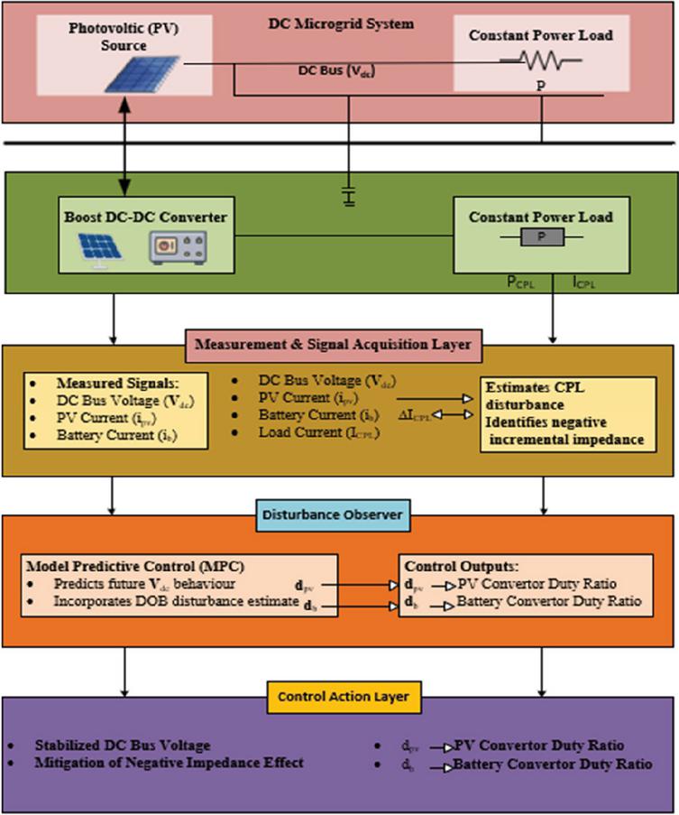
Figure 1 Proposed layer-wise control architecture for DC microgrid stability enhancement.
2.1.1 PV subsystem modelling
The photovoltaic array is represented by a current source with nonlinear voltage-current characteristics. The dynamical behaviour of the PV boost converter is represented through the following differential equations shown in Equations (1) and (2):
| (1) | ||
| (2) |
Here, and are the voltage and current of the solar cell, respectively; denotes the inductor current, indicates the duty cycle of the boost converter, and stands for the DC bus voltage. and represent the inductance and capacitance of the photovoltaic (PV) side DC-DC boost converter.
2.1.2 Battery energy storage system modelling
The battery is connected by means of a bidirectional DC-DC converter, which is functioning in buck-boost mode. The power supply’s dynamic behaviour is represented in Equations (3) and (4):
| (3) | ||
| (4) |
Here, refers to the voltage at the battery terminals, denotes the current through the inductor, indicates the control duty ratio, and stands for the current of the battery, either in charging or discharging mode. and represent the inductance and capacitance of the battery-side bidirectional DC-DC converter.
The change in battery current is subject to physical limitations, especially during the transitions between the charging and discharging modes. The limitations come from the nature of the battery, its internal resistance, and the heat generated, because quick current shifts can lead to faster ageing, higher losses, and overheating.
2.1.3 DC bus dynamics
The power exchanged between the sources and the load is summed up by the capacitor at the DC bus. The following equation represents the dynamics of the DC bus voltage, given in Equation (5):
| (5) |
Here, DC bus capacitance, which stores energy and smooths voltage variations, represents the DC bus voltage, denotes the rate of change of DC bus voltage with respect to time, Duty ratio of the PV-side DC-DC boost converter, Inductor current of the PV boost converter. Duty ratio of the bidirectional battery DC-DC converter. Battery converter current, Current drawn by the constant power load.
2.1.4 CPL modelling
The CPL represents a situation of constant power consumption , which yields a nonlinear current-voltage relationship, as expressed in Equation (6):
| (6) |
Even though acquiring a linear approximation near the point of operation leads to discovering this destabilizing characteristic, it can be expressed as given in Equation (7):
| (7) |
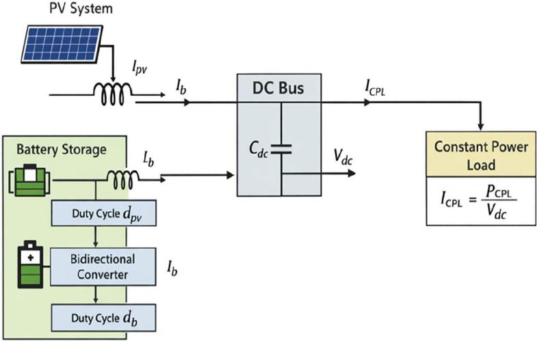
Figure 2 System configuration of the DC microgrid with constant power load.
Here, represents the incremental (small-signal) impedance of the CPL. The mentioned instability is mainly due to this incremental impedance, which acts as a primary source of instability within DC microgrids. Figure 2 depicts a DC microgrid powered by PV and battery, in which a solar photovoltaic system and a DAC battery energy storage system supply power to a shared DC bus that feeds a constant power load. The DC bus capacitor ensures a stable bus voltage, whereas the CPL draws a current that is inversely proportional to the bus voltage, thereby indicating the source of negative impedance-induced instability more distinctly.
2.2 Constant Power Load and Negative Impedance Representation
A CPL is defined as a load that keeps consuming the same amount of power regardless of the supply voltage changes [29]. In a DC microgrid, this phenomenon is usually seen in very accurately controlled power electronic loads like motor drives, data centres, and DC-DC converters. These loads have such strict regulations that always adjust their input current to eliminate the effect of the voltage fluctuations, and this basically changes the DC microgrid’s dynamic behaviour. By this self-regulating action, the loads bring in strong nonlinearities and also lower the natural system damping, especially during low-voltage or high-load situations. As a result, the use of CPLs makes DC microgrids more prone to oscillations, transient instability, and voltage collapse unless proper control strategies are applied.
2.2.1 CPL current-voltage relationship
A CPL is characterized by its functionality to draw a constant amount of power, regardless of the supply voltage’s fluctuations. In contrast to passive loads, where the current and consequently the power consumed drops with the decrease of voltage, a CPL continuously controls its input current in such a way that power consumption remains constant, leading to a non-linear current-voltage relationship. The power drawn by the CPL at any instant is represented in Equation (8):
| (8) |
Here, refers to the DC bus voltage, and stands for the current drawn by the load. As the power is constant due to the intervention of the load controller, the load current can be given in Equation (9):
| (9) |
This formula evidently indicates that the CPL current is inversely proportional to the DC bus voltage.
2.2.2 Small-signal linearization of CPL
To assess stability, the model of the constant power inverter (CPI) is subjected to small perturbations, where the first derivative is taken at the steady-state operating point . The first-order Taylor expansion yields the small signal model expressed in Equation (10):
| (10) |
Next, the incremental impedance of the CPL is defined in Equation (11) as follows:
| (11) |
Here, represents the small-signal variation in the current drawn by the CPL due to a change in the DC bus voltage around an operating point. represents the small-signal variation in the DC bus voltage around its steady-state operating point. represents the incremental impedance of the CPL in a DC microgrid. denotes the steady-state DC bus voltage at the operating point, and represents the power consumed by the constant power load.
Small-signal analysis is necessary as constant power loads show nonlinear behaviour that is hard to examine directly under large-signal conditions. A steady operating point can be used for linearizing the system, and the CPL can be shown as an incremental impedance, thus its negative impedance characteristic is very well identified. Through this method, it becomes possible to apply stability analysis and controller design practically using linear control and impedance-based methods that are usually employed in DC microgrids.
2.2.3 Impact on DC bus dynamics
The constant power loads contribute to the system’s destabilizing behavior of CPL, which profoundly affects the DC bus dynamics by lowering the effective damping of the system [30]. The current demand of the CPL gets enlarged with small voltage disturbances, which in turn generates a positive feedback loop that magnifies the voltage dips instead of quelling them. This feedback leads to the DC bus voltage showing oscillatory behaviour, slower recovery after transients, and even instability, especially when the CPL power is high or the bus voltage is low. The dynamics of the DC bus capacitor are expressed by the relationship given in Equation (12):
| (12) |
Inserting the equation of the linearized CPL current given in Equation (13):
| (13) |
Where, represents the total source current injected into the DC bus by the generation and storage units in the DC microgrid. This mathematical statement shows the existence of a positive feedback term that causes a reduction in system damping and a movement of eigenvalues toward the right-half plane, thus resulting in instability.
2.2.4 Interaction with power electronic converters
Power electronic converters linked with the DC bus usually show finite output impedance characteristics. The total output impedance that is observed at the DC bus is given by Equation (14):
| (14) |
Because , as defined in Equation (15), the magnitude of the combined impedance is less, which may be a case of violating passivity conditions:
| (15) |
Where, represents the equivalent small-signal impedance of the DC microgrid as seen from the DC bus in the Laplace domain, represents the effective (output) impedance of the power electronic converter as seen from the DC bus.
This non-passive condition leads to:
• DC bus voltage oscillations
• Slow transient recovery
• Voltage collapse during large disturbances
2.2.5 Instability problem formulation
The instability issue in DC microgrids is caused by the interplay between the negative incremental impedance of constant power loads and the finite output impedance of power electronic converters connected to the DC bus. The interaction can make the entire system non-passive, which is a factor that reduces stability margins and causes the right-half-plane pole to migrate. As a result, the DC bus voltage is unable to track the reference value during disturbances, necessitating a controller that not only compensates for the CPL-induced negative impedance but also actively restores system stability. The instability problem caused by CPL can be restated as shown in Equation (16):
| (16) |
Thus, it is proven that a controller is necessary to negate the negative impedance effect and to bring back positive damping in the DC microgrid.
2.3 Problem Formulation for CPL-Induced Instability
In a DC microgrid that provides power to constant power loads, voltage control is the main goal in the system design and operation. The aim here is to maintain the DC bus voltage at the reference value without compromising the system stability even in dynamic operating conditions. Mathematically, this can be expressed in Equation (17):
| (17) |
Where denotes the target DC voltage, and S signifies the area of stable operation.
2.3.1 CPL-induced stability constraint
Analyzing the DC bus dynamics leads to the Equation (18):
| (18) |
Here, denotes the DC bus capacitance; represents the DC bus voltage; denotes the rate of change of the DC bus voltage with respect to time; represents the total current supplied by the sources; and denotes the current drawn by the constant power load.
While the current at the CPL is given by the relation as shown in Equation (19):
| (19) |
From these, it can be seen that fluctuations in the CPL power cause corresponding changes in the DC bus voltage. The application of small-signal analysis gives a negative incremental impedance, which is expressed in Equation (20):
| (20) |
This consequently introduces a destabilizing feedback term into the system, and the passivity conditions are violated when the following condition is satisfied, as given in Equation (21):
| (21) |
2.3.2 Disturbances and uncertainties
The DC microgrid has to cope with several disturbances and uncertainties, such as given in Equations (22) and (23):
| (22) | |
| (23) |
The nonlinear system dynamics absorb these disturbances, leading to changes in voltage levels and a reduction in the stability margins.
2.3.3 Need for advanced control strategy
Traditional linear controllers have a hard time keeping the system stable with the great nonlinearities and fast power changes brought about by CPLs. Therefore, a more sophisticated control method is necessary to achieve the control objectives formulated in Equation (24):
| (24) |
In such a way that the constraints of nonlinear system dynamics and disturbances are satisfied. represents the unstable eigenvalue (or dominant unstable pole) of the DC microgrid closed-loop system. The controller has to constantly counteract the negative impedance created by CPLs, cancel disturbances, and maintain strong regulation of DC bus voltage under various operating conditions.
3 Continuous-Time Model Predictive Controller Design
A continuous-time MPC strategy is designed for both the PV-side DC-DC boost converter [31] and the battery-side bidirectional DC-DC converter to alleviate the adverse impact of negative impedance caused by CPL on the system stability. The MPC makes use of the dynamic model of the DC microgrid to forecast the future system behaviour and simultaneously calculate the optimal control inputs in real time.
3.1 Modelling Assumptions and Practical Considerations
In order to connect the theoretical analysis with a practical implementation, this study uses a number of modelling assumptions. The power electronic converters are dealt with as average models, overlooking high-frequency switching ripples since the control aims are directed at low-frequency DC bus dynamics. The DC bus capacitor and line parameters are considered to be constant, which is a reasonable assumption for normal operating conditions. Small-signal linearization is done around a steady-state operating point to investigate the main dynamics related to CPL-induced instability. Even though non-idealities like switching delays, losses, and measurement noise are not modelled separately, their impact is indirectly dealt with by means of robust control design and confirmed through simulation. These assumptions help to reduce the complexity of the analysis, but at the same time, they keep the analysis grounded in practice.
3.2 System State-Space Model
The state-space model employs variables that have a clear physical interpretation, such as the currents of inductors and the voltages of capacitors, to express the most critical energy storage and transfer dynamics of the DC microgrid. The voltage of the DC bus capacitor is an important state that indicates the stability of the voltage in the presence of constant power load perturbations, whereas the current of the inductor on the battery side portrays the two-way charging and discharging process. These state variables make it possible to predict system dynamics accurately in the MPC context. The evolution of the nonlinear system is described mathematically in a continuous-time state-space format as follows, given in Equation (25):
| (25) |
In this equation, stands for the vector of states (currents in the inductor and voltages across the capacitor), and is the input vector that represents the control actions attributed to the converters’ duty cycles.
3.3 Prediction-Based Optimization
At every control instant, the MPC predicts the states of the system over the time horizon by reasoning. The prediction is done through the following Equation (26):
| (26) |
The optimization of the control process is done through a cost function expressed as follows are shown in Equation (27):
| (27) |
Where and are the reference signals, and are the corresponding factors for weighting.
4 Disturbance Observer Integration
The DOB is incorporated into the MPC strategy to enhance the robustness against CPL disturbances. The DOB, taking the measured DC bus voltage and current as inputs, estimates the sum of disturbances attributable to CPL nonlinearities and modelling uncertainties. The obtained disturbance estimate is then added to the MPC prediction model directly, thus enabling the controller to counteract its influence during the optimization process. In order to strengthen the resilience of the continuous-time MPC against nonlinearities and external disturbances caused by CPL, the control architecture is augmented with a DOB. The DOB gives an estimate of the total disturbances that are due to CPL power fluctuations, unmodeled dynamics, and parameter uncertainties, thus allowing for compensation in real time and getting better stability of the system.
4.1 Disturbed System Representation
The behaviour of the nonlinear DC microgrid can be characterized mathematically by the following Equation (28):
| (28) |
In this representation, is an unspecified disturbance vector that reflects fluctuations in the load represented by constant power, errors in modelling, and disturbances coming from outside.
4.2 Disturbance Modelling
The equation representing the voltage variation across the DC bus is given in Equation (29):
| (29) |
The term , which represents the equivalent disturbance, consists of the following components are shown in Equation (30):
| (30) |
That takes into consideration the nonlinear behaviour of the CPL and the uncertainties associated with the source and converter models.
4.3 Compensation within the MPC Framework
The estimated disturbance is included in the MPC forecasting model, d(t), which is the estimated disturbance, and it has been added to the control model as expressed in Equation (31):
| (31) |
The whole system behaviour, which is influenced by disturbances, can now be predicted accurately, and the control actions computed by the MPC can be such that the negative impedance effect due to CPL can be nullified during the process.
4.4 Robustness and Large-Signal Stability
The integrated DOB-MPC scheme keeps the DC bus voltage stability automatically compensating for disturbances in real time under the condition, as shown in Equation (32):
| (32) |
The system in the loop has bounded state trajectories and thus shows large-signal stability across a wide operating range, given in Equation (33):
| (33) |
5 Closed-Loop Implementation in DC Microgrid
The suggested control system merges the continuously operating MPC and the DOB into a single closed-loop framework to achieve coordinated control of the DC microgrid [31]. The integrated controller is used on the DC-DC boost converter at the PV side and on the battery-side bidirectional DC-DC converter to maintain power management in the case of constant power loads that is both stable and effective. Figure 3 shows a control architecture for a closed-loop DC microgrid that uses an MPC to control the PV and battery converters over DC bus voltage stability at constant power load. The disturbance observer estimates disturbances caused by the CPL and sends these disturbances back to the MPC, which then compensates for the negative impedance effects robustly and thus keeps the system operation stable.
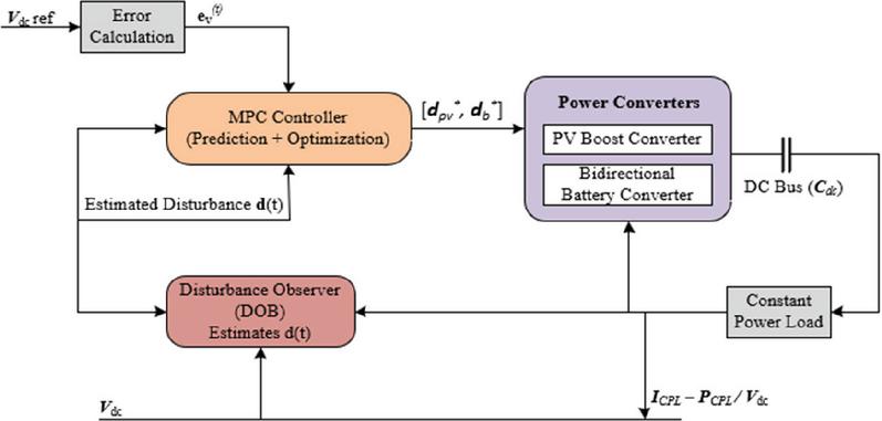
Figure 3 Integrated MPC and disturbance observer control scheme for DC microgrids with constant power loads.
5.1 Closed-Loop Control Structure
The closed-loop overall dynamics can be represented in the following manner, given in Equation (34):
| (34) |
Where represents the best control inputs produced by the MPC, and stands for the disturbance that has been estimated and is provided by the DOB. The main goal in this control task is to maintain the desired DC bus voltage level, as shown in Equation (35):
| (35) |
The MPC achieves this by manipulating the duty ratios of the converter to the extent that is presented in Equation (36):
| (36) |
Thereby, the control system operates continuously without any impact from load changes and external interferences.
5.2 PV Voltage and Current Control
The boost converter on the photovoltaic (PV) side controls the voltage and current from the PV to produce and feed in the power that is stable, and most outputs are given in Equations (37) and (38).
| (37) | ||
| (38) |
The MPC follows these references, taking into account the constraints of the converter and keeping the DC bus stability at the same time.
5.3 Battery Charge/Discharge Current Control
The bidirectional power converter manages the battery current in such a way as to equalize the power differences, as shown in Equation (39):
| (39) |
The battery either takes or gives out power depending on the DC bus voltage variations, and the load requirements are given in Equation (40):
| (40) |
Thus, power compensation is done smoothly. Figure 4 explains the closed-loop battery charge and discharge current controlling system, where deviations of the DC bus voltage are utilized for creating a reference for battery current. The battery current is regulated by the MPC-based current controller, which controls the duty cycle of the bi-directional DC-DC converter, allowing the battery to either provide or take power for the purpose of stabilizing the DC bus.
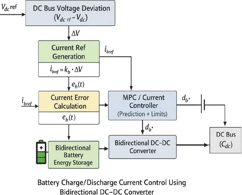
Figure 4 Control structure of bidirectional battery converter for DC microgrid applications.
5.4 Coordinated Subsystem Operation
The joint operation of the solar cell and battery subsystems achieves the power balance at the DC bus, shown in Equation (41):
| (41) |
Here, Power generated by the photovoltaic (PV) source, Power supplied or absorbed by the battery energy storage system, Power consumed by the CPL, Total system losses, including converter, line, and switching losses.
5.5 Large-Signal Stability Assurance
The closed-loop system implemented with disturbance estimation and predictive control produces bounded state trajectories, as presented in Equation (42):
| (42) |
Thus, securing the reliability and stability of operation throughout a wide range of loads and generation conditions.
6 Simulation Result
The simulation results demonstrate that the proposed controller successfully suppresses instability caused by constant power loads in the DC microgrid [32]. The DC bus voltage decreases from its nominal value of 400 V to approximately 265 V under open-loop conditions, highlighting the severe impact of CPL-induced instability. The uncontrolled system, under CPL power variations, suffers from extreme DC bus voltage oscillations caused by the CPL-induced instability, while the proposed control strategy quickly stabilizes the DC bus voltage with an insignificant overshoot. The proposed approach, in contrast to traditional controllers, not only greatly enhances damping characteristics but also assures quicker transient recovery and stable operation during large-signal disturbances, thus proving its ability to completely remove CPL-induced negative impedance effects. The suggested MPC-DOB control method was put into practice in MATLAB/Simulink, making use of Simscape Electrical to represent the DC microgrid parts such as converters, DC bus, and constant power loads. The continuous-time MPC and disturbance observer were implemented using custom MATLAB functions, which allowed precise assessment of voltage regulation, current control, and disturbance rejection under CPL variations through time-domain simulations.
Table 2 Simulation parameters
| Parameter Description | Symbol | Value | Unit |
| DC Bus Capacitance | 0.002 | F | |
| Reference DC Bus Voltage | 400 | v | |
| DC Bus Parasitic/Loss Resistance | 5 | ||
| Rated Battery Current | 10 | A | |
| Rated PV Source Current | 12 | A | |
| Constant Power Load Rated Power | 2,000 | W | |
| Nominal CPL Load Current | 5 | A | |
| Control Sampling Time | 0.0001 | s | |
| Simulation Step Size | 0.0001 | s | |
| Total Simulation Time | 0.35 | S | |
| Battery Converter Inductance | 2 | mH | |
| PV Boost Converter Inductance | 3 | mH | |
| Battery Nominal Voltage | 200 | V | |
| MPC Prediction Horizon | 5 | ms | |
| Disturbance Observer Gain | 200 |
The parameters utilized to model, control, and simulate a DC microgrid that is supplying a constant power load are completely presented in Table 2. The most important electrical parameters are DC bus capacitance, converter inductances, and nominal voltages that are responsible for the physical dynamics of the PV-battery system, while the load power and current values indicate the level of the CPL-induced negative impedance effect that is being experienced. The control-associated parameters like the MPC prediction horizon, sampling time, and disturbance observer gain define the proposed controller’s speed and robustness, while the simulation time settings allow an accurate evaluation of the system’s performance during disturbance in both transient and steady-state conditions.
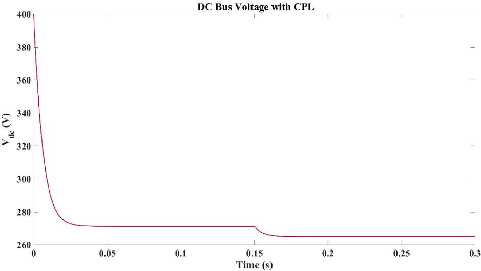
Figure 5 Open-loop DC bus voltage response under constant power load.
Figure 5 illustrates the behaviour of the DC bus voltage under CPL conditions with no significant compensation. The DC bus voltage drops steeply right at the beginning and then partly recovers. The sharp decrease in voltage is attributed to the negative incremental impedance of the CPL and reflects the system’s poor damping and possible instability. A small decrease in voltage is observed again when the CPL changing point is shifted, which verifies that operating at constant power magnifies voltage fluctuations and points out the requirement for a sophisticated control method to maintain the stability of the DC bus.
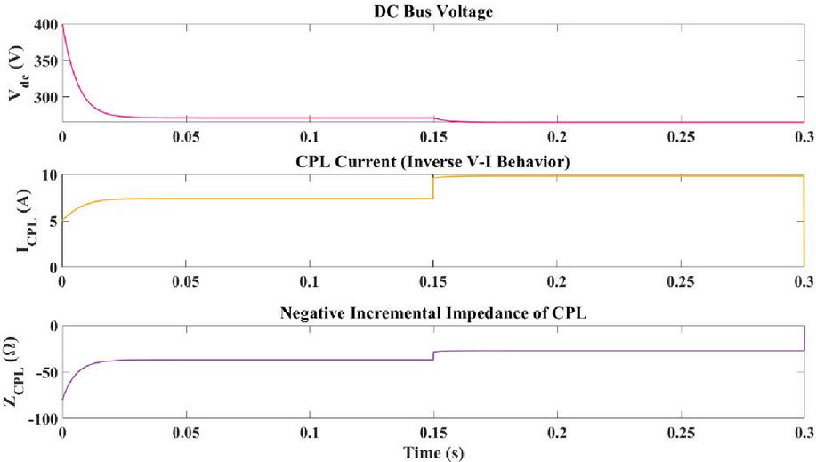
Figure 6 Dynamic behaviour of DC bus voltage and CPL negative impedance.
Figure 6 demonstrates the influence of CPL on DC microgrid stability through three main responses. The upper plot depicts a large decrease in DC bus voltage due to the CPL’s negative impedance characteristic, which means that there is a damping reduction, and voltage regulation becomes poor. The middle plot verifies the opposite voltage-current relationship of the CPL, with load current increasing as the bus voltage decreases, whereas the bottom plot shows the negative incremental impedance very clearly, proving that this behaviour is the main cause of system instability. It can be observed that the DC bus voltage drops from 400 V to nearly 265 V in the absence of control.
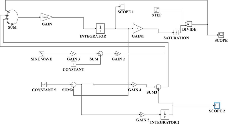
Figure 7 Block diagram of control logic and disturbance injection used in DC microgrid simulation.
Figure 7 illustrates the Simulink implementation of the control and disturbance generation logic used to analyze the behaviour of a DC microgrid under constant power load conditions. To model the nonlinear CPL dynamics and the controller action, the system uses summation blocks, gains, integrators, saturation, and division blocks. Through step and sine-wave inputs, disturbances are introduced to perform transient testing. Scopes are in place to monitor key internal signals, including voltage deviation, control response, and disturbance effects, thus allowing the validation of system stability and controller performance.
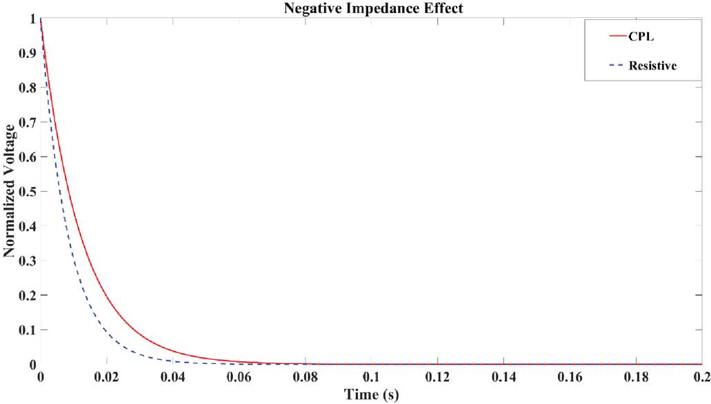
Figure 8 Negative impedance effect of CPL compared with resistive load.
The comparison of the two voltage responses is displayed in Figure 8, one from the CPL and the other from the conventional resistive load operating under identical conditions. The CPL curve shows a higher and quicker voltage drop because of its negative impedance characteristic, which makes disturbances in voltage stronger and pushes instability faster. On the other hand, the resistive load has a more gradual and less intense response, making it clear that CPLs are one of the factors causing instability in DC microgrids.)
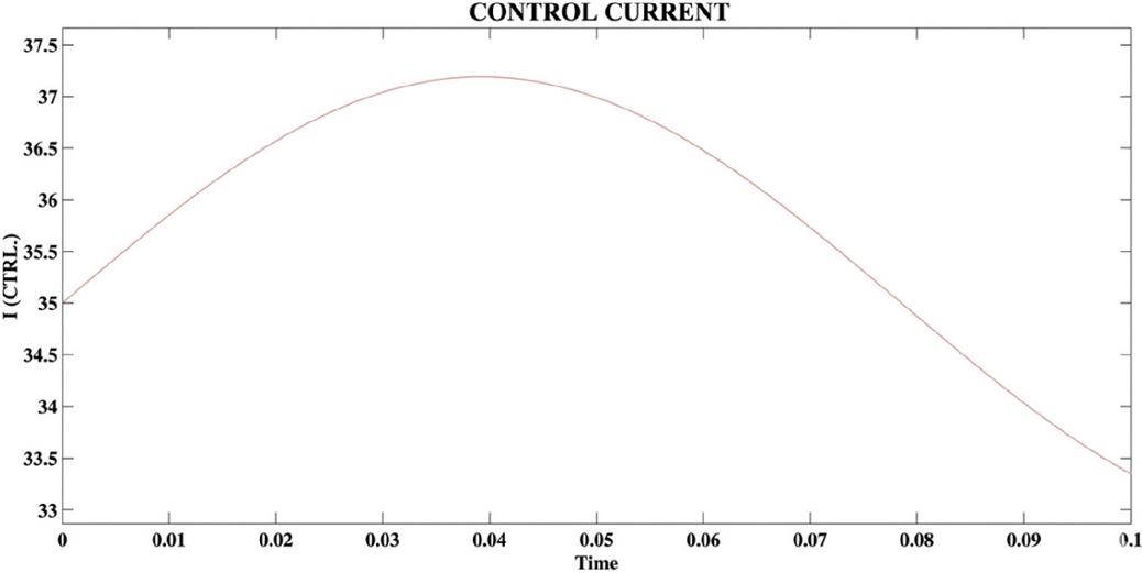
Figure 9 Control current response of the proposed controller under CPL disturbance.
Figure 9 shows the control current output of the proposed controller in relation to the constant power load-induced DC bus voltage fluctuations. The monotonous and limited change of the control current signifies effective damping injection and stable control action without sudden oscillations. This feature proves that the controller is always compensating for CPL-related disturbances and, at the same time, ensuring system stability and smooth transient performance.
Table 3 Quantitative analysis of DC bus voltage instability under constant power load operation
| Reference_ | Final_ | Voltage_ | CPL_ | Final_CPL | Incremental_ | System_ |
| Vdc_V | Vdc_V | Deviation_V | Power_W | Current_A | Impedance_Ohm | Stability |
| 400 | 265.052077 7 | 134.947922 3 | 2600 | 9.809393017 | 27.0202323 | Voltage collapse tendency |
Table 3 shows the quantitative effect of a steady power load on the stability of the DC microgrid under open-loop conditions. A considerable difference between the reference DC bus voltage and the final stable state voltage is noted, which signifies serious voltage decay owing to the CPL’s negative incremental impedance feature. The negative impedance value obtained and the higher load current serve as proof of the characteristic destabilizing effect of constant power loads that lead to a voltage collapse tendency, thereby necessitating an advanced control strategy.
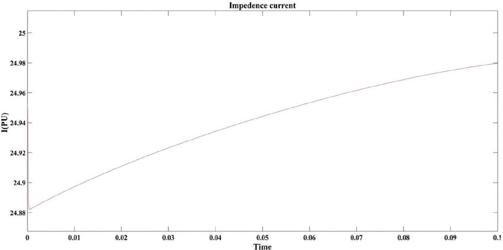
Figure 10 Impedance current response under the proposed control strategy.
The impedance current response of the DC microgrid under the proposed control strategy is depicted in Figure 10. The gradual increase in impedance current, well-damped and gradual, reflects the controller’s successful reshaping of system impedance; hence, the CPL’s negative incremental impedance is mitigated. This controlled behaviour signifies better system stability and smooth current dynamics without oscillatory transients.
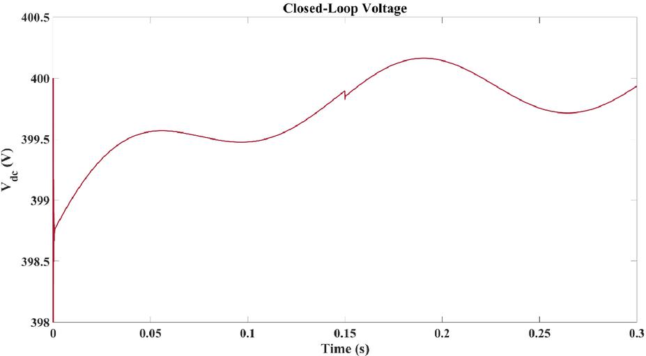
Figure 11 Closed-loop voltage stabilization in DC microgrid with constant power load.
The closed-loop DC bus voltage response using the new control strategy is illustrated in Figure 11. The voltage settles down to the desired value very fast with slight overshoot and oscillations that are well-damped, thus proving the instability caused by the CPL has been compensated effectively. This finding proves that the controller has stabilized the DC bus voltage regulation under the condition of nonlinear load dynamics.
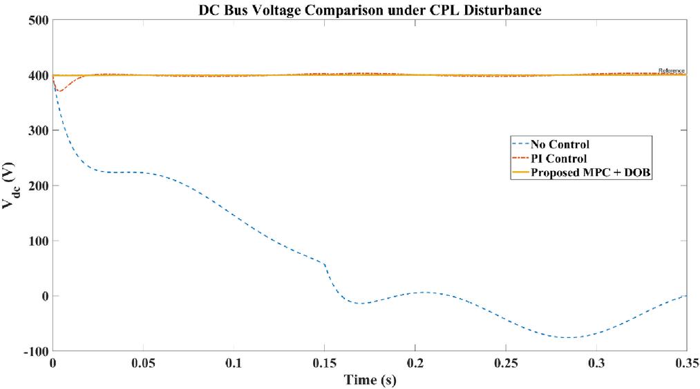
Figure 12 Performance comparison of DC bus voltage regulation under constant power load disturbance.
Figure 12 illustrates how the DC bus voltage responds to a constant power load disturbance using various control strategies. The unregulated state caused by the negative impedance effect of the CPL led to a complete drop in the DC bus voltage, which was extremely unstable. The voltage regulation using the conventional PI controller was, however, very limited with considerable fluctuations in the voltage level. On the other hand, the proposed MPC combined with the (MPC DOB) kept the DC bus voltage very close to the reference value, thus showing excellent disturbance rejection and powerful stability.
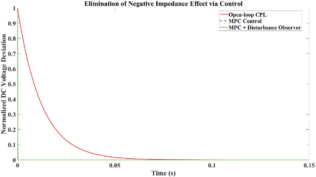
Figure 13 Suppression of negative impedance effect in DC microgrids.
Figure 13 presents the impact of the suggested control strategy regarding the negative impedance effect removal due to the constant power load. In the scenario without feedback control, the constant power load leads to a significant voltage shift that takes a long time to return to normal, which is a sign of weak damping and instability. The incorporation of the (MPC) along with further improvement through the disturbance observer results in the quick extinction of the voltage deviation to zero, thus signalling fast convergence, better damping, and solid stabilization of the DC bus.
The results of the simulation depicted strongly support the ability of the suggested MPC–DOB controller to control the DC bus voltage and to reduce CPL-induced instability, yet the validation is still confined to a simulation environment. Real DC microgrids could have unmodeled nonlinearities, measurement noise, and switching delays that would not be fully reflected in simulations. Hence, it is necessary to conduct further experiments, using either a real-time or hardware-based DC microgrid setup, to confirm the results and consider this as an important future work direction.
6.1 Discussion
The stability of the DC microgrid is greatly affected by the constant power loads, as shown by the simulation results that also prove the ability of the proposed controller to mitigate this destabilizing effect. In the case of open-loop operation, the CPL acts with a destabilizing characteristic that causes a DC bus voltage deviation of considerable magnitude from its reference value, hence indicating a tendency towards voltage collapse and system instability. The implementation of the proposed continuous-time model predictive controller, along with a disturbance observer, leads to a significant improvement in the DC bus voltage regulation, characterized by reduced oscillations, faster transient response, and increased steady-state accuracy even in the presence of sudden changes in load power. The predictive capability of the MPC gives room for the proactive control action that can reshape system dynamics and increase effective damping, while the disturbance observer gives the exact estimation and compensation of the nonlinearities and unmodeled disturbances resulting from CPL. Moreover, the coordinated control of the PV boost converter and the bidirectional battery converter allows for smooth power sharing and stable charge-and-discharge operation, thereby saving individual subsystems from the adverse effects of excessive stress. The results indeed substantiate that the proposed control strategy reaps the benefits of eliminating the negative impedance increase effect caused by constant power loads retarding the stability, robustness, and reliability of DC microgrids with high penetration of power electronic loads.
7 Conclusion
This research work put forward a novel control method that completely removed the adverse impedance rise effect due to constant power loads in DC microgrids. The instability inherent to CPLs was formulated analytically and verified by simulation, where severe DC bus voltage deviation and voltage collapse tendency were observed for open-loop conditions. To overcome this problem, a continuous-time model predictive controller combined with a disturbance observer was created and used on the PV-side boost converter as well as on the bidirectional battery converter. The method developed is capable of reshaping system dynamics, of nonlinearities due to CPLs being compensated for and of regulating stable DC bus voltage even when the load and generation are varying.
The simulation results have proven that the new MPC-d disturbance observer framework performs better in terms of enhancing stability, damping, and robustness of the system than the traditional control methods. The voltage of the DC bus shows quicker transient reaction, fewer oscillations, and a more precise steady-state value during sudden changes in CPL power. Besides, the coordinated control of renewable and storage subsystems makes power sharing smooth and battery charge-discharge operation reliable. These findings prove that the suggested controller is an excellent and practical choice for the stability and power quality enhancement of DC microgrids with a significant contribution of power electronic loads.
Declarations
Data Availability
The data supporting the findings of this study are available from the corresponding author upon reasonable request.
Conflicts of Interest
The authors declare that they have no known financial or personal conflicts of interest that could have influenced this work.
Funding Statement
This research did not receive any specific grant from funding agencies in the public, commercial, or not-for-profit sectors.
Author Contributions
All authors contributed to the study. A. Liu designed the controller and led the analysis; S. Hao, Y. Li, and Y. Miao performed the modeling and simulations; H. Zuo assisted with validation and manuscript preparation. All authors reviewed and approved the final manuscript.
Ethical Approval
This study does not inv olve human participants or animals; ethical approval was not required.
Consent to Participate
Not applicable, as the study does not include human participation.
Consent to Publication
All authors consent to the publication of this work.
Competing Interests
The authors declare no competing interests.
References
[1] Keskinis S, et al. Techno-economic photovoltaic-battery energy storage system microgrids with diesel backup generator: a case study in industrial loads in Germany comparing load-following and cycle-charging control. Energies, 2025, 18(24): 6463.
[2] Zaid S A, et al. Stabilization of DC microgrids using frequency-decomposed fractional-order control and hybrid energy storage. Fractal Fract., 2025, 9(10): 670.
[3] Thaler B, Pirker G, Wermuth N. Hydrogen production with grid-connected electrolysis: scenariobased analysis of the EU criteria for renewable fuels. Environ. Res. Lett., 2025, 20(2): 024017.
[4] Yalçın F, Köse H, Savaşcıhabeç A. A novel IGBT-based silicone carbide rectifier design for improved energy efficiency in telco data centers. Energies, 2025, 18(2): 348.
[5] Ullah M, et al. Dynamic response of droop-controlled grid-forming inverters under varying grid impedances for enhanced stability in microgrids. Appl. Sci., 2025, 15(23): 12562.
[6] Abuhaiba A. Reducing greenhouse gas emissions from micro gas turbines using silicon carbide switches. Methane, 2025, 4(4): 26.
[7] Farajpour N, Bandara Y M N D Y, Lastra L, Freedman K J. Negative memory capacitance and ionic filtering effects in asymmetric nanopores. Nat. Nanotechnol., 2025, 20(3): 421-431.
[8] Palash D A, Roy T K, Alam Z, Oo A M T. Design and experimental validation of a composite FRL-NFTISMC and BSC for DC-bus voltage stabilization in CPL-based DC microgrids. IET Power Electron., 2025, 18(1): e70012.
[9] Wahidujjaman M, et al. Enhanced stability and performance of islanded DC microgrid systems using optimized fractional order controller and advanced energy management. Eng. Rep., 2025, 7(4): e70122.
[10] Zhang W, et al. Research on circulating-current suppression strategy of MMC based on passivitybased integral sliding mode control for multiphase wind power grid-connected systems. Electronics, 2025, 14(13): 2722.
[11] Han D, Qi H, Wang S, Hou D, Wang C. Adaptive stepsize forward-backward pursuit and acoustic emission-based health state assessment of high-speed train bearings. Struct. Health Monit., 2024, 24(6): 3523–3542.
[12] Zheng H, et al. Learning from models beyond fine-tuning. Nat. Mach. Intell., 2025, 7(1): 6–17.
[13] Abdolahi M, Adabi J, Mousazadeh Mousavi S Y. Implementation and control of a buck-boost converter connected to a constant power load in a DC microgrid. Electr. Eng., 2025, 107(2): 1483–1492.
[14] Komiyama S, Uchiyama K, Masuda K. Combined robust control for quadrotor UAV using model predictive control and super-twisting algorithm. Drones, 2025, 9(8): 576.
[15] Gupta R, Singh N. Impedance interaction and power flow enhancement in DC microgrids using interval type-2 fuzzy logic and active voltage stabilizer-based hybrid damping controller. Electr. Eng., 2025, 107(3): 3323–3336.
[16] Islam M S, Bushra I J, Roy T K, Chowdhury J M. Stability enhancement of DC microgrids under CPLs using secretary bird optimization algorithm-tuned backstepping-GITSM control: design, simulation, and experimental approach. IET Power Electron., 2025, 18(1): e70118.
[17] Al-Shammaa A A, et al. RST-controlled interleaved boost converters for enhanced stability in CPL-dominated DC microgrids. Symmetry, 2025, 17(10): 1585.
[18] Mahdavi M, Banejad M, Gholizadeh Narm H, Aminzadeh H. Consensus based distributed secondary control for current sharing and voltage restoration considering local loads and constant power loads in DC microgrids. Int. J. Model. Simul., 2025, 45(5): 1875–1897.
[19] Moradi-Khaligh E, Karimi S, Sadabadi M S. Robust decentralised voltage control strategy for DC microgrids considering disturbances and polytopic-type uncertainties. IET Electr. Power Appl., 2025, 19(1): e70016.
[20] Ramos-Paja C A, Serna-Garcés S I, Saavedra-Montes A J. Battery power interface to mitigate load transients and reduce current harmonics for increasing sustainability in DC microgrids. Sustainability, 2025, 17(17): 7987.
[21] Pratticò D, et al. Enhancing power quality and reducing costs in hybrid AC/DC microgrids via fuzzy EMS. Energies, 2025, 18(22): 5985.
[22] Anbuchandran S, Arumuga babu M, Stephen D S, Thinakaran M. Dynamic voltage regulation in DC microgrids using super-twisting sliding mode controllers. Electr. Eng., 2025, 107(11): 14205–14227.
[23] Belal E K, et al. Development of a novel IoT-based hierarchical control system for enhancing inertia in DC microgrids. Smart Cities, 2025, 8(5): 166.
[24] Nawaz F, et al. Enhanced distributed coordinated control strategy for DC microgrid hybrid energy storage systems using adaptive event triggering. Electronics, 2025, 14(16): 3303.
[25] Tesfaye M, et al. Enhanced power sharing control of an islanded DC microgrid with unmatched line impedances. Electronics, 2025, 14(8): 1654.
[26] Chakrapani BC, Arunkumar CR, Srinivas P, Manthati UB. Minimization of circulating currents in parallel DC-DC boost converter using non-linear droop control for battery energy storage system. Distributed Generation & Alternative Energy Journal, 2022: 819–844.
[27] Iqbal SJ, Mohammad SS. Power management, control and optimization of photovoltaic/battery/fuel cell/stored hydrogen-based microgrid for critical hospital loads. Distributed Generation & Alternative Energy Journal, 2022: 1027–1054.
[28] Yamada H. Autonomous decentralized cooperative control DC microgrids realized by directly connecting batteries to the baseline. Electronics, 2025, 14(7): 1356.
[29] Dias M P, et al. Voltage balancing of a bipolar DC microgrid with unbalanced unipolar loads and sources. Processes, 2025, 13(11): 3734.
[30] Jayashree S, Caroline S, Swarna Devi K M, Lokesh D. Hybrid aquila African vulture optimization-based stability enhanced DC-DC boost converter with constant power load. J. Electr. Eng. Technol., 2026, 21(1): 735–747.
[31] Feng Q, et al. A multi-vector modulated model predictive control based on coordinated control strategy of a photovoltaic-storage three-port DC-DC converter. Energies, 2025, 18(12): 3208.
[32] Islam M S, Roy T K, Bushra I J. Marine predators algorithm-based robust composite controller for enhanced power sharing and real-time voltage stability in DC-AC microgrids. Algorithms, 2025, 18(8): 531.
Biographies

Anjiang Liu was born in Tongren, Guizhou, P.R. China, in 1991. He graduated from Guizhou University in China with a master’s degree. Currently, he works at the Electric Power Research Institute of Guizhou Power Grid Co., Ltd. His research interests include distribution network operation and maintenance.

Shuqing Hao was born in Anyang, Henan, P.R. China, in 1998. He graduated from Guizhou University in China with a master’s degree. Currently, he works at the Electric Power Research Institute of Guizhou Power Grid Co., Ltd. His research interests include distribution network operation and maintenance.

Yue Li was born in Bijie, Guizhou, P.R. China, in 1993. He graduated from North China Electric Power University in China with a master’s degree. Currently, he works at the Electric Power Research Institute of Guizhou Power Grid Co., Ltd. His research interests include distribution network operation and maintenance.

Yu Miao was born in Guiyang, Guizhou, P.R. China, in 1995. He graduated from Guizhou University in China with a master’s degree. Currently, he works at the Electric Power Research Institute of Guizhou Power Grid Co., Ltd. His research interests include automation and maintenance of distribution networks.

Hongyu Zuo Li was born in Zunyi, Guizhou, P.R. China, in 2000. He graduated from Harbin Institute of Technology in China with a bachelor’s degree. Currently, he works at Zunyi Power Supply Bureau of Guizhou Power Grid Company.His research interests include automation and maintenance of distribution networks.
Distributed Generation & Alternative Energy Journal, Vol. 41_5, 1417–1452
doi: 10.13052/dgaej2156-3306.4158
© 2026 River Publishers