A Ground-Wire Active Current Based Fault-Location Method for Smart Monitoring of Underground Mine Cable Distribution Systems
Mingzhen Zhang1 and Haipeng Huang2,*
1School of Artificial Intelligence and Automation, Huazhong University of Science and Technology, Wuhan 430074, China
2Inner Mongolia Weihua Mining Co., Ltd., Ordos 016299, China
E-mail: zhangmingzhen@outlook.com; huanghaipeng12563@163.com
*Corresponding Author
Received 27 April 2026; Accepted 28 May 2026
Abstract
Underground mine cable distribution systems are critical industrial local energy infrastructures, where ground faults can lead to production interruption, difficult fault searching, and safety risks. This paper proposes a ground-wire active-current based fault-location method for smart monitoring of underground mine cable distribution systems. The method uses zero-sequence voltage as the fault trigger and phase reference, and measures ground-wire currents at both ends of each monitored cable section. By extracting the active components of the head-end and tail-end ground-wire currents, a fault judgment quantity is constructed through their algebraic summation. Theoretical analysis shows that, for non-faulted cable sections, the active ground-wire current mainly behaves as through-current and is largely cancelled by the double-ended summation. In contrast, for the faulted cable section, the fault current flows from the fault point toward both ends, producing a dominant active-current summation. Simulation results under transition resistances from 0 to 1000 verify that the proposed method can correctly identify internal cable-section faults and distinguish terminal busbar/switchgear faults without falsely locating a healthy cable section. A distributed smart monitoring architecture integrating ground-current sensors, zero-sequence voltage measurement, RS485/LoRa communication, and master-station processing is also presented. The proposed method provides an interpretable and practical solution for online fault location, faster fault isolation, and improved reliability of underground mine local energy distribution systems.
Keywords: Underground mine cable distribution system, ground-wire current, active current component, fault location, single-phase-to-ground fault, smart monitoring, local energy system, LoRa communication.
1 Introduction
Reliable electrical distribution is a fundamental requirement for underground mine operation, where power interruptions can directly affect production continuity, ventilation, drainage, transportation, communication, and personnel safety. In contrast to conventional urban or overhead distribution networks, underground mine cable distribution systems are typically installed in spatially constrained and harsh environments, with long cable routes, many branches, multiple distribution rooms, switch stations, and grounding points. These characteristics make fault detection and isolation more difficult, especially when the cable route is hidden, access is limited, and the fault location cannot be visually inspected. Therefore, fast and accurate fault location is not only a protection requirement, but also an enabling technology for safe, resilient, and intelligent mine energy operation.
From the perspective of modern energy systems, underground mine power networks can be regarded as critical industrial local energy systems. Their operation increasingly depends on distributed sensing, communication, monitoring, and decision-support functions, which are also central elements of smart local energy systems and smart distribution networks [1–4]. In smart distribution systems, fault location, isolation, and service restoration are key functions for improving reliability and reducing outage duration [5, 6]. For underground industrial networks, such functions are particularly important because prolonged fault searching may lead to production shutdown, reduced energy utilization efficiency, and increased safety risk. Thus, a fault-location method suitable for underground mine cable distribution systems should satisfy several practical requirements: online applicability, compatibility with branched cable structures, sensitivity to high-resistance ground faults, clear section-level location capability, and implementability using distributed monitoring hardware.
Single-phase-to-ground faults are among the most common and important fault types in medium-voltage distribution systems, especially in non-solidly grounded, compensated, or resistance-grounded networks [7–10]. In underground mine cable systems, three-core power cables are widely used, and their metallic shields, armor layers, grounding conductors, and grounding electrodes form an extended grounding network. When the main insulation between a phase conductor and the metallic sheath or armor is damaged, the fault current enters this grounding network and redistributes along the cable grounding path. As a result, the ground-wire current contains information about the faulted section, fault-current direction, and fault location. This physical feature provides an opportunity to develop a fault-location method that directly uses ground-wire current instead of relying only on feeder-level zero-sequence current.
Many fault-location methods have been proposed for power distribution and underground cable systems. Impedance-based methods estimate the fault distance from measured voltage and current quantities and are attractive because of their relatively simple implementation [11–13]. However, their accuracy may be affected by fault resistance, load uncertainty, distributed capacitance, cable parameter errors, and branched network structure. Traveling-wave methods can provide high location accuracy by using transient wave arrival times or high-frequency features [14–16], but they usually require high sampling rates, precise time synchronization, and reliable detection of the initial wavefront, which may increase cost and implementation complexity in underground mine environments. Signal-injection and offline testing methods are useful for maintenance after a fault, but they are less suitable for continuous online monitoring and rapid fault isolation [17]. Data-driven methods, including wavelet-transform, neuro-fuzzy, support-vector, and deep-learning approaches, have also been investigated for cable and distribution-network fault location [18–22]. These methods can improve classification and pattern recognition performance, but they often require representative training data, careful feature design, or extensive simulation datasets, and their interpretability may be limited in protection-oriented engineering applications.
For underground cables, sheath-current or ground-current based methods are especially relevant because the metallic sheath and grounding system are directly involved in fault-current circulation. Jensen et al. proposed online fault location for underground AC cables using sheath currents, showing that sheath-current measurements can provide useful fault-location information in cable systems [23]. Other studies have analyzed cable sheath voltage, sheath current, grounding arrangement, and equivalent circuits for cable grounding systems under line-to-ground faults [24, 25]. These studies indicate that grounding-path electrical quantities can reveal fault behavior that may not be fully captured by conventional feeder measurements. However, many existing approaches focus on transmission cables, single-core cable systems, or distance estimation, while section-level location in branched three-core underground mine cable distribution systems remains challenging.
In compensated or resonant-grounded distribution networks, active-current-based ground-fault detection has long been recognized as useful because the capacitive current and arc-suppression-coil current are mainly reactive, whereas the resistive component is more closely related to the fault path [7, 8]. Wattmetric and active-component methods can improve the selectivity of ground-fault detection, but conventional implementations are usually feeder-oriented and may not directly identify the exact faulty cable section in an underground cable network. In addition, if the fault occurs at a busbar or inside switchgear rather than inside a cable section, a section-location algorithm should avoid falsely identifying a healthy cable section. Therefore, a practical mine cable monitoring method should distinguish between cable-section faults and terminal busbar or switchgear faults.
To address these challenges, this paper proposes a ground-wire active current based fault-location method for smart monitoring of underground mine cable distribution systems. The method installs ground-wire current sensors at both ends of each monitored cable section and uses the zero-sequence voltage as the phase reference to extract the active components of the measured ground-wire currents. The key principle is that, for a non-faulted cable section, the active ground-wire current behaves mainly as through-current, so the active current components measured at the two ends cancel when consistent reference directions are used. In contrast, for the faulted cable section, the fault current flows from the fault point toward both ends, so the two active current components add constructively. Therefore, the summation of the double-ended active ground-wire currents can be used as a fault-location criterion.
Table 1 Comparison of existing underground cable fault-location methods
| Suitability for | ||||
| Required | Main | Main | Underground Mine | |
| Method | Signal | Advantage | Limitation | Cable Systems |
| Impedance-based method | Voltage and current phasors | Simple principle and mature implementation | Sensitive to fault resistance, cable parameters, load uncertainty, and branch structure | Medium |
| Traveling-wave method | High-frequency transient voltage/current | High theoretical location accuracy | Requires high sampling rate, time synchronization, and reliable wavefront detection | Low to medium |
| Signal-injection/offline test method | Injected diagnostic signal | Useful for maintenance after outage | Not ideal for online monitoring or rapid isolation | Medium |
| Data-driven method | Measured or simulated features | Strong pattern-recognition capability | Requires representative training data and may have limited interpretability | Medium |
| Zero-sequence current/voltage method | Feeder-level zero-sequence quantities | Mature for ground-fault detection | Often identifies faulty feeder rather than exact cable section | Medium |
| Sheath/ground-current method | Cable sheath or ground-wire current | Directly reflects grounding-path fault behavior | Requires robust section-level criterion and sensor deployment | High |
| Proposed ground-wire active-current method | Double-ended ground-wire current and zero-sequence voltage | Section-level location, high-resistance fault sensitivity, and busbar-fault discrimination | Requires sensors at both ends of monitored cable sections | High |
2 System Configuration and Fault-Current Mechanism
Underground mine distribution networks commonly use medium-voltage three-core cables to supply equipment distributed across shafts, roadways, substations, switch stations, pumping stations, ventilation systems, and production areas. Because these cables are installed underground or in enclosed routes, direct inspection is difficult. The presence of multiple branches and intermediate distribution points further increases the challenge of rapidly identifying the exact faulted section after a ground fault.
As shown in Figure 1, a three-core underground cable includes phase conductors, main insulation, metallic shielding, armor, and an outer sheath. The metallic shield, armor layer, grounding conductors, cable terminal grounding points, and grounding electrodes are interconnected to form a distributed grounding network. Under normal balanced operation, the ground-wire current is small. However, when insulation failure occurs between a phase conductor and the metallic shield or armor, the fault current enters this grounding network, causing measurable changes in the magnitude and phase of ground-wire currents at cable terminals.
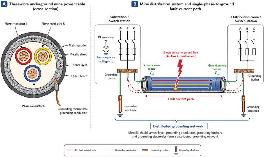
Figure 1 System configuration and single-phase-to-ground fault-current path in an underground mine three-core cable distribution system.
The proposed method uses the different current-direction characteristics of faulted and non-faulted cable sections. In a non-faulted section, the fault-related ground current mainly behaves as through-current, so the active current components measured at the two ends tend to cancel when consistent reference directions are used. In the faulted section, the fault current flows from the fault point toward both cable terminals, so the two active current components add constructively. This difference forms the physical basis of the double-ended ground-wire active-current fault-location criterion.
The monitoring configuration therefore installs ground-current sensors at both ends of each cable section and obtains the zero-sequence voltage from the PT secondary side at an accessible substation, distribution room, or switch station. During a ground fault, is used as the phase reference for active-current extraction, and the two end measurements are combined to determine whether the monitored cable section contains the fault point.
2.1 Three-Core Cable Grounding Structure
In a three-core underground mine cable, the phase conductors are enclosed by insulation and surrounded by metallic shielding and armor layers. These metallic layers provide mechanical protection, electric-field shielding, and a grounding path under fault conditions. At cable terminals, the metallic shield and armor are connected to the grounding system through grounding conductors and grounding busbars. Therefore, for a distribution network consisting of several cable sections, the cable metallic layers and grounding electrodes jointly form an extended grounding network.
This grounding network is important for both safety and fault detection. From a safety perspective, it provides a low-impedance path for fault current and helps limit dangerous touch voltage. From a monitoring perspective, it provides a measurable path through which the ground fault current is redistributed. Since the ground-wire current is directly influenced by the location of the fault point, monitoring the ground-wire current at both ends of each cable section can provide section-level fault-location information.
2.2 Single-Phase-to-Ground Fault Current Path
When a single-phase-to-ground fault occurs inside a cable section, the fault current flows from the faulted phase conductor into the metallic shield or armor layer at the fault point. After entering the grounding network, the current divides into multiple paths according to the impedance of the grounding conductor, cable metallic layers, grounding electrodes, and earth return path. In a branched mine cable network, part of the current may flow toward the source-side terminal, while another part may flow toward the load-side terminal or nearby grounding points.
For the cable section containing the fault, the fault current originates from an internal point and flows outward toward both terminals. This creates a current pattern in which the ground-wire current sensors at both ends detect components associated with the same fault source. When their reference directions are defined as flowing into the local grounding bus or grounding electrode, the two active current components have the same algebraic contribution to the fault criterion.
For cable sections that do not contain the fault point, the ground-wire current associated with the fault is mainly a through-current. That is, it enters one end of the section and leaves the other end. With consistent reference directions, the two measured active current components tend to have opposite algebraic signs. Therefore, their summation is close to zero. This difference between through-current behavior and fault-source behavior is the essential mechanism used by the proposed method.
2.3 Role of Zero-Sequence Voltage and Active Current
During a single-phase-to-ground fault, the zero-sequence voltage increases and is used as the fault trigger. When it exceeds the preset threshold, the system synchronously samples the zero-sequence voltage and the ground-wire currents at both ends of each monitored cable section. The zero-sequence voltage is then used as the phase reference for extracting the active current components.
Because capacitive current and arc-suppression-coil compensation current are mainly reactive, the active component better reflects the resistive fault path. Therefore, this paper focuses on the head-end and tail-end active ground-wire currents, denoted as and , which are used to construct the proposed fault judgment quantity.
Physically, the active component represents the part of the ground-wire current that is in phase with the zero-sequence voltage. This component is more closely associated with the resistive part of the ground-fault path, including the fault transition resistance and grounding resistance. In contrast, the cable-to-ground capacitive current and the arc-suppression-coil compensation current mainly contribute reactive components. Therefore, using the active component suppresses the influence of charging current and compensation current and improves the selectivity of the fault-location criterion. This interpretation is consistent with wattmetric ground-fault detection principles, but the proposed method extends the idea from feeder-level detection to double-ended cable-section location.
2.4 Measurement Configuration for Section-Level Monitoring
To implement section-level fault location, each monitored cable section is equipped with two ground-wire current sensors: one at the head end and one at the tail end. The sensors should be installed with the same polarity convention across all cable sections. A consistent reference direction is necessary because the proposed criterion depends on the algebraic summation of active current components.
The monitoring configuration requires three main types of signals: (1) zero-sequence voltage, used for ground-fault triggering and active-current phase reference; (2) head-end ground-wire current of each cable section; (3) tail-end ground-wire current of each cable section.
Once a ground fault is detected, the system calculates the active components of all measured ground-wire currents and evaluates the double-ended active-current summation for every cable section. The section with a dominant active-current summation is identified as the faulted cable section. If no section-level summation exceeds the threshold, but a terminal current is dominant, the fault is interpreted as a possible busbar or switchgear fault rather than a cable internal fault.
Table 2 Symbols and definitions
| Symbol | Definition | Unit |
| Index of the monitored cable section | — | |
| Index of the faulted cable section | — | |
| Zero-sequence voltage used as phase reference | V | |
| Zero-sequence voltage threshold for ground-fault triggering | V | |
| Ground-wire current measured at the head end of cable section | A | |
| Ground-wire current measured at the tail end of cable section | A | |
| Active component of relative to | A | |
| Active component of relative to | A | |
| Active component of the single-phase-to-ground fault current | A | |
| Fault judgment quantity of cable section | A | |
| Threshold of the fault judgment quantity | A | |
| Fault transition resistance | ||
| Equivalent phase-to-ground capacitance of cable section | F | |
| Equivalent grounding resistance | ||
| Arc-suppression coil inductance at the neutral point | H | |
| Parallel neutral grounding resistance | ||
| Number of samples per fundamental-frequency cycle | — |
3 Theoretical Basis of Ground-Wire Active Current Distribution
The mechanism described above indicates that the active ground-wire current has a directional distribution pattern that differs between faulted and non-faulted cable sections. To formulate this observation mathematically, this section develops the theoretical basis of ground-wire active current distribution using the zero-sequence network and the superposition principle.
3.1 Zero-Sequence Representation of a Single-Phase-to-Ground Fault
For a single-phase-to-ground fault, the cable distribution system can be analyzed using the zero-sequence network. In a neutral grounding system with an arc-suppression coil and parallel resistance, the zero-sequence current contains both reactive and active components. The reactive component is mainly related to cable-to-ground capacitance and coil compensation, while the active component is associated with the resistive fault path and grounding network.
Since this paper aims to locate the faulted cable section, the active component of the ground-wire current is used as the main indicator. For cable section , the head-end and tail-end ground-wire currents are denoted as and , and their active components with respect to the zero-sequence voltage are denoted as and . Both current reference directions are defined consistently as flowing into the local grounding busbar or grounding electrode.
3.2 Superposition of Ground-Wire Current Components
Based on the linearity of the equivalent zero-sequence circuit, the ground-wire current in a cable section can be decomposed into several components. In general, the ground-wire current of section can be expressed as
| (1) |
where is the component associated with the zero-sequence voltage and distributed cable capacitance, is the component associated with the neutral-point current, and is the component associated with the fault-point current.
Since the proposed criterion uses the active component of the ground-wire current, the analysis can be simplified to the active-current contribution:
| (2) |
where is the active component caused by the neutral-point current, and is the active component caused by the fault-point current. This simplification is reasonable because the capacitive current and arc-suppression-coil current are predominantly reactive, while the resistive fault path contributes primarily to the active component. The supporting material follows this same idea by focusing on the active part of the ground-wire current distribution rather than the reactive capacitive and compensation currents.
3.3 Active Current Behavior in Non-Faulted Cable Sections
For a non-faulted cable section, the active ground-wire current behaves mainly as a through-current. In other words, the current enters one end of the cable section and leaves the other end through the grounding path. When the current reference directions at the two ends are both defined as flowing into the local grounding busbar, the two measured active components have opposite algebraic signs.
Therefore, for a non-faulted cable section , the sum of the two end active currents is approximately zero:
| (3) |
where denotes the faulted cable section.
The cancellation relationship in (3) is based on several practical assumptions. First, the head-end and tail-end ground-current sensors should use the same polarity convention. Second, the two current measurements should correspond to the same fault interval and should be referred to the same zero-sequence voltage phase reference. Third, the non-faulted cable section is assumed not to contain an internal injection point of fault current; therefore, the measured active current mainly enters from one end and leaves from the other end. In a real underground mine grounding network, the cancellation may not be perfect because of unequal grounding resistances, distributed leakage, cable parameter variation, sensor magnitude or phase error, and background grounding current. For this reason, the proposed method does not use an ideal zero criterion. Instead, a practical threshold is introduced to separate the small residual summation of healthy sections from the dominant summation of the faulted section.
Equation (3) is the key cancellation property of non-faulted sections. It indicates that, although a non-faulted section may carry ground-wire current during a system ground fault, the double-ended active-current summation suppresses the through-current component. This is important for branched underground mine cable networks, because a large ground current may appear in healthy cable sections due to grounding-network redistribution, but it should not be interpreted directly as an internal cable fault.
3.4 Active Current Behavior in the Faulted Cable Section
For the cable section containing the fault point, the current behavior is different. The fault current enters the metallic shield, armor layer, or grounding conductor at the fault location and then flows from the fault point toward both ends of the cable section. Under the same reference direction convention, the active current components measured at the head end and tail end no longer cancel. Instead, they add constructively.
Therefore, for the faulted cable section ,
| (4) |
where is the active component of the fault current flowing through the grounding network.
Equation (4) shows that the double-ended active-current summation of the faulted section is significantly larger than that of the non-faulted sections. This provides a direct mathematical basis for identifying the faulted cable section.
3.5 Fault-Location Implication
Combining (3) and (4), the expected distribution of the double-ended active-current summation can be written as
| (5) |
This relationship indicates that the faulted cable section can be identified by finding the section with a dominant active-current summation. In practical systems, the value for non-faulted sections may not be exactly zero because of cable-to-ground capacitance, insulation leakage, current-transformer error, sensor polarity deviation, and calculation error. Therefore, a threshold is required in the practical algorithm. The detailed construction of the fault judgment quantity and the threshold-based location logic are presented in the next section.
4 Proposed Fault-Location Criterion and Algorithm
Based on the active-current distribution derived in Section 3, this section develops the practical fault-location criterion and algorithm. The proposed method uses synchronized measurements of zero-sequence voltage and double-ended ground-wire currents. The zero-sequence voltage is used both as the ground-fault trigger and as the phase reference for extracting the active components of the ground-wire currents.
4.1 Synchronized Sampling and Phasor Calculation
When a single-phase-to-ground fault occurs, the zero-sequence voltage rises from its normal background level. Therefore, the monitoring system first determines whether
| (6) |
where is the zero-sequence voltage threshold for initiating the fault-location process. If (6) is satisfied, the system synchronously samples the zero-sequence voltage and the head-end and tail-end ground-wire currents of each monitored cable section.
For one fundamental-frequency cycle with sampling points, the sampled zero-sequence voltage can be expressed as , where . The real and imaginary components of its fundamental phasor are calculated as
| (7) | ||
| (8) |
Thus,
| (9) |
Similarly, for cable section , the head-end and tail-end ground-wire current phasors are calculated as
| (10) | ||
| (11) |
where the real and imaginary components are obtained from the corresponding sampled current waveforms using the same fundamental-frequency phasor extraction method.
4.2 Active Component Extraction
The active component of the ground-wire current is defined as the projection of the current phasor onto the direction of the zero-sequence voltage phasor. For the head-end current of cable section , the active component is calculated as
| (12) |
Similarly, the active component of the tail-end current is
| (13) |
where
| (14) |
Equations (12) and (13) extract the in-phase component of the ground-wire current relative to . This step reduces the influence of reactive capacitive current and compensation current, which are less useful for identifying the faulted cable section.
4.3 Fault Judgment Quantity
For each monitored cable section, the proposed fault judgment quantity is defined as the algebraic sum of the active components measured at the two ends:
| (15) |
where the reference directions of and are both defined as flowing into the local grounding busbar or grounding electrode.
Based on the theoretical analysis in Section 3, the expected value of is close to zero for non-faulted cable sections and significantly larger for the cable section containing the fault point. Therefore, the faulted cable section can be identified by comparing with a predefined threshold.
4.4 Threshold Setting
In an idealized model, is zero for non-faulted cable sections. In practical systems, however, nonzero values may appear because of distributed cable-to-ground capacitance, insulation leakage, current-transformer error, sensor polarity deviation, sampling error, and phasor calculation error. Therefore, a threshold is required to avoid false identification.
A practical threshold can be selected according to the maximum expected non-faulted active-current summation:
| (16) |
where is the maximum expected value of under healthy through-current conditions, and is a reliability coefficient.
If the cable-to-ground capacitive current is used as the main threshold reference, the threshold may be expressed as
| (17) |
where is the angular frequency, is the maximum equivalent phase-to-ground capacitance among the monitored cable sections, and is the measured zero-sequence voltage. In practice, the threshold may also include margins for current-transformer error and monitoring-device calculation error.
In practical deployment, the threshold can be determined through a combination of parameter-based estimation and commissioning calibration. Before operation, the background ground-wire current of each monitored cable section can be recorded under normal operating conditions. The maximum residual active-current summation observed during normal operation and non-faulted through-current conditions can be used as the baseline value. A safety margin is then added to account for current-transformer ratio error, phase-angle error, A/D sampling error, cable capacitance uncertainty, and grounding-resistance variation. Therefore, the practical threshold may be written in the general form
where represents the maximum measured background residual value of section , represents the estimated residual caused by distributed cable capacitance and grounding-network imbalance, represents the measurement uncertainty, and is a reliability coefficient larger than 1. The simplified threshold expression in (17) can be used when cable capacitance is the dominant residual source. For field application, section-specific thresholds are recommended because cable length, grounding resistance, and sensor accuracy may differ among sections.
The uploaded supporting material notes that, although the theoretical analysis predicts zero fault quantity for non-faulted cable sections, simulation with realistic cable capacitance produces small nonzero values. Therefore, a threshold should be used to distinguish true faulted-section behavior from background or capacitive effects.
4.5 Cable-Section Fault and Busbar Fault Decision Logic
The proposed method distinguishes between cable-section faults and terminal busbar or switchgear faults using the following logic.
First, calculate for all monitored cable sections. If a unique cable section satisfies
| (18) |
and
| (19) |
then cable section is identified as the faulted cable section.
If all cable sections satisfy
| (20) |
then no internal cable-section fault is identified. In this case, the system examines the individual active ground-wire current magnitudes at cable terminals. The terminal with the largest active current is selected as the likely busbar or switchgear fault location:
| (21) |
where represents the head end and represents the tail end of cable section .
If multiple cable sections exceed the threshold simultaneously, the result is flagged as abnormal rather than assigning a single faulted section. This condition may be caused by sensor polarity errors, communication errors, multiple simultaneous faults, or unusual grounding-network conditions.
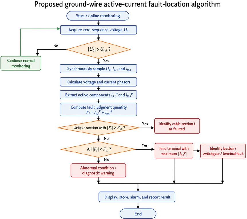
Figure 2 Flowchart of the proposed ground-wire active-current fault-location algorithm.
4.6 Algorithm Workflow
The workflow of the proposed fault-location algorithm is shown in Figure 2. The algorithm first monitors the zero-sequence voltage and triggers the fault-location procedure when . It then synchronously samples , , and , calculates their phasors, extracts the active current components and , and computes the fault judgment quantity for each cable section. By comparing with the threshold , the method identifies a cable-section fault, a busbar/switchgear fault, or an abnormal diagnostic condition, after which the result is displayed, stored, alarmed, and reported.
A data-quality check is performed before the final location decision. If the zero-sequence voltage measurement is unavailable, the active-current reference cannot be established and the algorithm reports a voltage-reference data-quality alarm. If either the head-end or tail-end ground-wire current of a monitored section is missing, saturated, or outside the valid measurement range, the corresponding section is not assigned a normal fault-location result. Instead, the system reports an incomplete-measurement alarm for that section. When multiple sections have invalid data, the master station should withhold automatic section-level identification and request manual inspection or repeated acquisition.
The fault-location decision logic and the practical implementation requirements are summarized in Tables 3 and 4, respectively.
Table 3 Fault-location decision logic
| Condition | Interpretation | Location Result |
| Zero-sequence voltage below trigger threshold | No ground fault is detected | Normal monitoring |
| Zero-sequence voltage above trigger threshold | Ground fault is detected | Start location algorithm |
| A unique cable section has the largest fault judgment quantity and exceeds the threshold | Fault current enters the grounding network inside this cable section | Faulted cable section |
| All cable-section fault judgment quantities are below the threshold, but one terminal active current is dominant | Fault is likely at a busbar, switchgear, or cable terminal | Terminal fault |
| Multiple cable sections exceed the threshold | Ambiguous condition, possible sensor error, abnormal grounding path, or multiple faults | Diagnostic warning |
| Required measurement data are missing or invalid | Calculation result is not reliable | Data-quality alarm |
Table 4 Practical implementation requirements
| Requirement | Purpose |
| Same installation direction for all ground-current sensors | Ensures correct algebraic summation of active current components |
| Synchronized sampling of zero-sequence voltage and ground-wire currents | Enables accurate phasor calculation and active-current extraction |
| Double-ended ground-current measurement for each monitored cable section | Supports section-level fault location |
| Zero-sequence voltage measurement from PT secondary side | Provides ground-fault trigger and phase reference |
| Threshold calibration based on cable parameters and measurement errors | Reduces false fault-section identification |
| Time stamping or coordinated acquisition among monitoring units | Improves consistency in distributed monitoring systems |
| Data-quality check for missing or abnormal measurements | Prevents incorrect location result due to communication or sensor failure |
5 Simulation Model and Test Conditions
To verify the proposed ground-wire active-current fault-location method, a three-phase simulation model of an underground mine cable distribution system was established. The model includes five medium-voltage cable sections, distributed grounding points, cable-to-ground capacitance, and a neutral grounding branch composed of an arc-suppression coil with a parallel resistance.
The simulation focuses on single-phase-to-ground faults, which directly involve the metallic shield, armor layer, grounding conductor, and grounding electrodes. For each case, the head-end and tail-end ground-wire currents are obtained, the zero-sequence voltage is used as the phase reference, and the fault judgment quantity is calculated for each monitored cable section.
Figure 3 shows the simulation model. Two fault-location categories are considered: internal cable-section faults and terminal busbar/switchgear faults. These cases are used to evaluate both section-level fault identification and the ability to avoid falsely assigning a terminal fault to a healthy cable section.
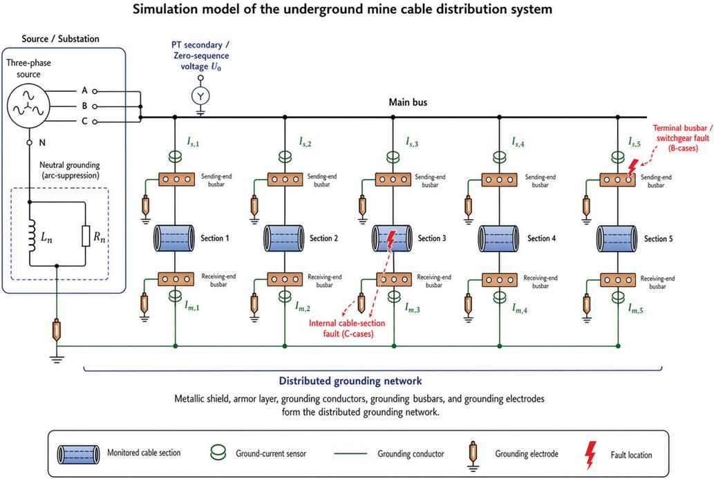
Figure 3 Simulation model of the underground mine cable distribution system.
5.1 Cable and Grounding Parameters
The cable parameters used in the simulation are summarized in Table 5. The model includes five cable sections with different lengths. Each cable section contains the conductor, metallic shield, armor layer, and distributed cable-to-ground capacitance. These parameters affect the ground-wire current distribution, especially the small nonzero fault judgment quantities observed in non-faulted sections.
In the ideal theoretical analysis, the active-current summation of a non-faulted cable section is approximately zero. However, in a practical cable network, the distributed capacitance, grounding resistance, and cable structural parameters cause small residual currents. Therefore, the simulation model includes cable capacitance and grounding effects to more realistically evaluate the proposed criterion. The supporting material also notes that, when realistic cable-to-ground capacitance is considered, the fault judgment quantity of non-faulted sections is not exactly zero, which justifies the use of a threshold in the fault-location algorithm.
Table 5 Cable and grounding parameters used in the simulation
| Cable Section | Shield Resistance | Armor Resistance | Cable Capacitance | Length |
| Section 1 | 1.075 | 0.414 | 0.652 | 2 km |
| Section 2 | 1.075 | 0.414 | 0.652 | 2 km |
| Section 3 | 1.612 | 0.621 | 0.978 | 3 km |
| Section 4 | 0.917 | 0.778 | 0.532 | 2 km |
| Section 5 | 0.917 | 0.778 | 0.532 | 2 km |
| Note: The parameters are based on the simulation data provided in the supporting material. Units should be finalized according to the original modeling convention before submission. | ||||
5.2 Fault Scenarios
To evaluate the robustness of the method under different grounding conditions, fault transition resistance was varied over four values: 0 , 10 , 100 , and 1000 . These cases represent metallic or low-resistance faults as well as high-resistance ground faults. High-resistance faults are especially important because the ground-wire current magnitude becomes smaller as fault resistance increases, making accurate fault location more challenging.
Two fault-location categories are simulated: (1) Cable-section fault: the single-phase-to-ground fault occurs inside a monitored cable section. In this case, the proposed criterion should produce a dominant for the faulted section. (2) Terminal busbar or switchgear fault: the single-phase-to-ground fault occurs at the cable terminal, busbar, or switchgear side. In this case, all section-level fault judgment quantities should remain below the threshold, while the terminal with the largest active ground-wire current indicates the likely fault location.
The simulated fault scenarios are summarized in Table 6.
Table 6 Simulated fault scenarios
| Case | |||
| Group | Fault Location | Fault Resistance | Expected Diagnostic Result |
| C1 | Internal cable section | (0 ) | Faulted cable section identified |
| C2 | Internal cable section | (10 ) | Faulted cable section identified |
| C3 | Internal cable section | (100 ) | Faulted cable section identified |
| C4 | Internal cable section | (1000 ) | Faulted cable section identified |
| B1 | Terminal busbar/switchgear | (0 ) | Terminal fault identified |
| B2 | Terminal busbar/switchgear | (10 ) | Terminal fault identified |
| B3 | Terminal busbar/switchgear | (100 ) | Terminal fault identified |
| B4 | Terminal busbar/switchgear | (1000 ) | Terminal fault identified |
5.3 Evaluation Quantities
For each simulated case, the head-end and tail-end ground-wire currents of all monitored cable sections are recorded. The active components and are calculated using the zero-sequence voltage as the phase reference. The section fault judgment quantity is then obtained as
| (22) |
The location result is evaluated using three main indicators: (1) whether the faulted cable section has the largest ; (2) whether the largest exceeds the threshold ; (3) whether busbar or switchgear faults can be distinguished from internal cable-section faults.
For cable-section faults, successful location requires that the faulted section has a unique dominant above the threshold. For terminal busbar or switchgear faults, successful location requires that all section-level values remain below the threshold, while the largest terminal active current points to the corresponding terminal location.
6 Simulation Results and Performance Evaluation
This section evaluates the proposed ground-wire active-current fault-location method using the simulation model and fault scenarios described in Section 5. The performance is examined from four perspectives: ground-wire current waveform response, cable-section fault-location results, busbar/switchgear fault discrimination, and robustness under different transition resistances. The simulation results show that the proposed fault judgment quantity can clearly distinguish the faulted cable section from healthy sections and can also avoid misidentifying terminal busbar faults as internal cable-section faults.
6.1 Ground-Wire Current Response Under Different Transition Resistances
Figure 4 shows the representative ground-wire current waveforms under different transition resistances. As the transition resistance increases from 0 to 1000 , the ground-wire current amplitude decreases significantly. This trend is consistent with the expected behavior of single-phase-to-ground faults: a larger transition resistance limits the fault current and reduces the measurable current in the grounding network.
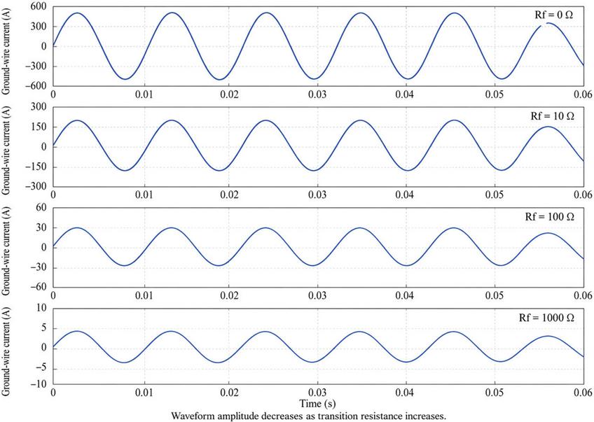
Figure 4 Ground-wire current waveforms under different transition resistances. As the transition resistance increases, the ground-wire current amplitude decreases, which highlights the need for a fault-location criterion that remains effective under high-resistance grounding conditions.
Although the total current magnitude decreases at high fault resistance, the proposed method does not rely only on the absolute current amplitude at a single terminal. Instead, it uses the active-current relationship between the head-end and tail-end measurements of each cable section. Therefore, even when the fault current becomes smaller, the faulted section can still be identified if its double-ended active-current summation remains above the threshold.
The supporting material also shows that the ground-wire current magnitude decreases as the transition resistance increases, and notes that high-resistance grounding faults must be considered when evaluating the reliability of the location method.
6.2 Cable-Section Fault Location Results
For an internal cable-section fault, the fault current enters the metallic shield, armor layer, and grounding conductor at the fault point and then flows toward both ends of the faulted section. Therefore, the active current components at the two ends of the faulted section add constructively. In contrast, the ground-wire current in non-faulted sections mainly appears as through-current, and the two end active components approximately cancel.
This behavior is reflected by the fault judgment quantity . For all simulated cable-section fault cases, the faulted cable section produced a dominant , while the non-faulted sections remained below the corresponding threshold. Table 7 summarizes representative cable-section fault results under different transition resistances.
Table 7 Cable-section fault simulation results
| Dominant | |||||
| Fault | |||||
| Fault | Zero-Sequence | Threshold | Judgment | Location | |
| Resistance | Voltage | Quantity | Margin | Location Result | |
| 0 | 5950.3 V | 10.964 A | 510.5 A | 46.6 | Correct cable section identified |
| 10 | 3014.4 V | 5.540 A | 259.9 A | 46.9 | Correct cable section identified |
| 100 | 553.5 V | 1.020 A | 47.9 A | 47.0 | Correct cable section identified |
| 1000 | 60.4 V | 0.111 A | 5.2 A | 46.8 | Correct cable section identified |
The location margin in Table 7 is defined as
| (23) |
where is the fault judgment quantity of the faulted cable section. A value greater than 1 indicates that the faulted section can be detected. In all four cases, the margin is much greater than 1, which indicates strong separation between the faulted section and the threshold.
The results show that the proposed method remains effective even when the transition resistance reaches 1000 . Although the absolute current magnitude is much smaller in the high-resistance case, the adaptive threshold also decreases with the zero-sequence voltage level, allowing the faulted section to remain distinguishable.
Figure 5 compares the section-level fault judgment quantity for different transition resistances. In all four cases, Section 3 produces a dominant active-current summation that is far above the corresponding threshold, while the remaining sections stay well below the threshold. This confirms the theoretical expectation that the faulted cable section produces a constructive summation of the head-end and tail-end active ground-wire currents, whereas non-faulted sections mainly exhibit through-current cancellation.
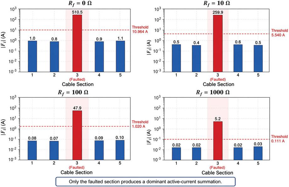
Figure 5 Fault judgment quantity distribution for cable-section faults.
Figure 6 further evaluates the robustness of the proposed criterion by plotting the fault-location margin versus transition resistance. The margin remains approximately 46–47 for all tested cases, which is far above the detection boundary of 1. This indicates that the proposed method maintains a stable separation between the faulted-section indicator and the threshold, even when the transition resistance increases to 1000 .
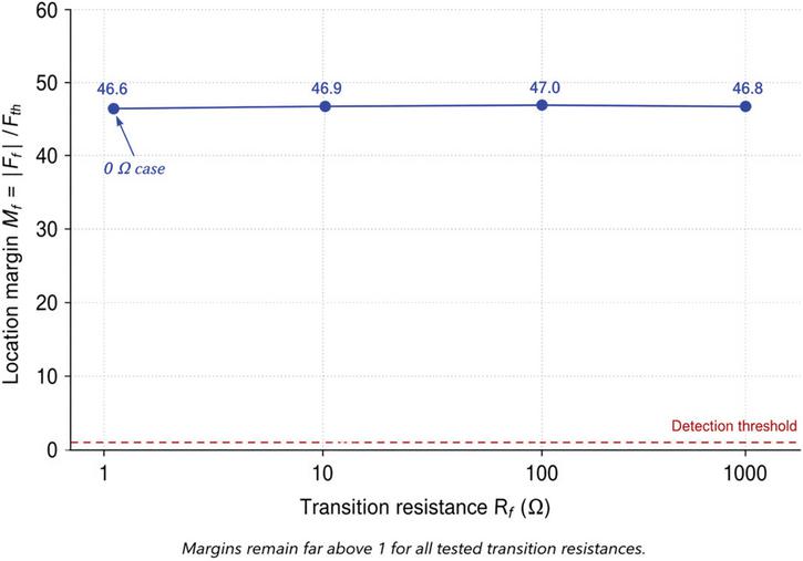
Figure 6 Fault-location margin versus transition resistance.
6.3 Busbar and Switchgear Fault Discrimination
A terminal busbar or switchgear fault produces a different current pattern from an internal cable-section fault. When the fault occurs at a busbar or switchgear terminal, the fault current is not injected into the middle of a monitored cable section. Instead, the resulting ground-wire current is mainly observed as through-current for the connected cable sections. Therefore, the double-ended fault judgment quantity remains below the section-fault threshold for all cable sections.
Table 8 summarizes the busbar/switchgear fault simulation results. In all tested cases, the maximum section-level fault judgment quantity remained below the threshold. Therefore, the proposed algorithm did not incorrectly identify a healthy cable section as faulted. Instead, the terminal with the largest active ground-wire current was used to identify the likely busbar or switchgear fault location.
In practice, a fault very close to a cable terminal may produce a diagnostic pattern between an internal cable-section fault and a terminal busbar/switchgear fault. Therefore, the proposed method should be interpreted as a section-level location method rather than a precise distance-to-fault method. If the section-level fault judgment quantity exceeds the threshold, the fault is located within the monitored cable section, including a possible near-end cable insulation fault. If all section-level quantities remain below the threshold but one terminal current is dominant, the fault is classified as a terminal-side fault, including busbar, switchgear, or terminal-connection faults. For ambiguous near-terminal cases, the algorithm can report a “terminal/cable-end suspected fault” to guide targeted inspection of both the cable end and the associated switchgear compartment.
Table 8 Busbar/switchgear fault simulation results
| Maximum | Dominant | ||||
| Fault | Zero-Sequence | Threshold | Section-level | Terminal | |
| Resistance | Voltage | (Fth) | (Fi) | Current | Location Result |
| 0 | 5950.3 V | 10.964 A | 1.3 A | 490.7 A | Terminal busbar/switchgear fault identified |
| 10 | 3014.4 V | 5.540 A | 0.6 A | 248.6 A | Terminal busbar/switchgear fault identified |
| 100 | 553.5 V | 1.020 A | 0.1 A | 45.7 A | Terminal busbar/switchgear fault identified |
| 1000 | 60.4 V | 0.111 A | 0.09 A | 5.09 A | Terminal busbar/switchgear fault identified |
The busbar fault results demonstrate an important advantage of the proposed method. If only individual terminal current magnitude were used, the large current at the terminal could be mistakenly interpreted as a cable-section fault. By contrast, the double-ended active-current summation suppresses through-current behavior and allows the algorithm to distinguish terminal faults from internal cable faults.
Figure 7 compares the diagnostic patterns of an internal cable-section fault and a terminal busbar/switchgear fault. For the internal cable-section fault, the fault judgment quantity of the faulted section exceeds the threshold by a large margin, producing a clear section-level location result. In contrast, for the busbar/switchgear fault, all section-level judgment quantities remain below the threshold, although a dominant terminal active current is observed. This distinction shows that the proposed method can avoid falsely identifying a healthy cable section when the fault is actually located at a terminal busbar or switchgear.
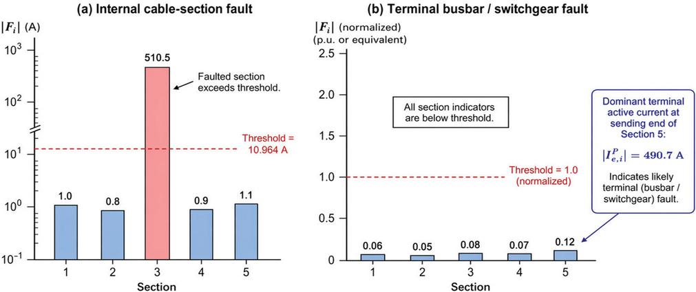
Figure 7 Diagnostic pattern comparison between cable-section fault and busbar fault.
6.4 Heatmap-Based Visualization of Fault Indicators
To provide a compact view of the fault-location behavior across all simulated cases, the normalized fault judgment quantity can be visualized as a heatmap:
| (24) |
where indicates that the corresponding cable section exceeds the fault-location threshold.
Figure 8 summarizes the normalized fault judgment quantities across all simulated cable-section and busbar fault cases. For internal cable-section faults, the heatmap shows a single dominant value at Section 3, with far greater than 1, indicating that the threshold is clearly exceeded only at the faulted section. For busbar/switchgear faults, all normalized values remain below 1, confirming that no internal cable-section fault is falsely identified. This heatmap provides a compact visual confirmation of both section-location capability and busbar-fault discrimination.
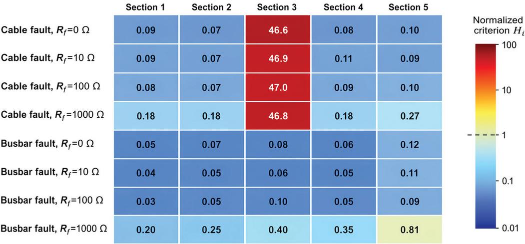
Figure 8 Heatmap of normalized fault judgment quantities across simulated cases. Hi 1 indicates threshold exceeded.
6.5 Overall Performance Summary
The overall simulation performance is summarized in Table 9. The proposed method correctly located all simulated internal cable-section faults and correctly distinguished all simulated busbar/switchgear faults. No false cable-section identification occurred in the busbar fault cases.
Table 9 Summary of performance under all simulated cases
| Number | Correct | False | High-resistance | ||
| of | Location | Cable-section | Case | ||
| Scenario Type | Cases | Cases | Alarms | Successful | Overall Result |
| Internal cable-section fault | 4 | 4 | 0 | Yes | Correctly identified faulted cable section |
| Terminal busbar/switchgear fault | 4 | 4 | 0 | Yes | Correctly distinguished terminal fault |
| All simulated cases | 8 | 8 | 0 | Yes | Successful location in all cases |
These results support the theoretical analysis in Section 3. For non-faulted cable sections, the active ground-wire current behaves mainly as through-current, and the double-ended active-current summation remains small. For the faulted cable section, the current flows from the fault point toward both ends, resulting in a large active-current summation. For terminal busbar or switchgear faults, all cable-section summations remain below the threshold, while the dominant terminal current indicates the likely faulted terminal. Figure 9 shows the qualitative performance comparison between the proposed method and representative fault-location methods for underground mine cable distribution systems. The proposed method provides section-level location, high-resistance fault sensitivity, and compatibility with distributed online monitoring.
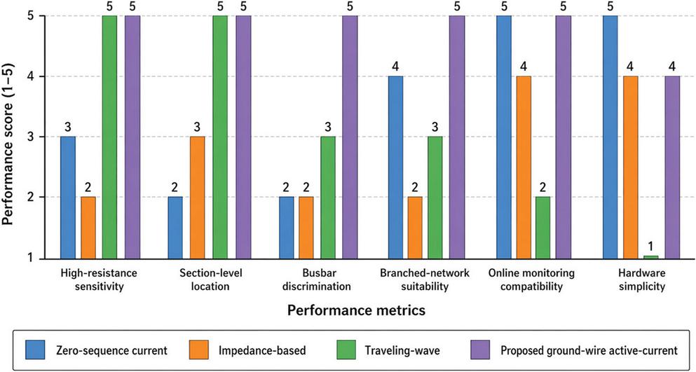
Figure 9 Overall performance comparison of fault-location indicators.
6.6 Discussion of Result Implications
The simulation results indicate that the proposed method has three practical advantages for underground mine cable distribution systems. First, the method provides section-level fault location rather than only feeder-level detection. This is important in underground mine networks, where many cable sections may be connected through multiple switch stations and distribution rooms. Second, the method has good sensitivity to high-resistance ground faults. Although the ground-wire current decreases with increasing transition resistance, the active-current summation of the faulted section remains clearly above the threshold in the simulated cases. Third, the method can distinguish internal cable-section faults from terminal busbar or switchgear faults. This avoids unnecessary inspection or isolation of healthy cable sections and improves the practical value of the method for smart monitoring systems.
Overall, the results demonstrate that the proposed ground-wire active-current criterion is suitable for smart online monitoring of underground mine cable distribution systems. By combining distributed current sensing, zero-sequence voltage reference, active-current extraction, and threshold-based decision logic, the method can provide a clear and interpretable fault-location result under different grounding fault conditions.
The present validation is based on simulation cases designed to verify the main fault-current mechanism and the section-level decision logic. Additional validation is still required before large-scale field deployment. Future work should evaluate the method under different faulted sections, different fault positions along the cable, unequal grounding resistances, variable cable parameters, background leakage current, sensor magnitude and phase errors, asynchronous sampling, communication delay, and multiple grounding-network configurations. Hardware-in-the-loop testing and field-event data from operating mine distribution systems would further verify the practical robustness of the proposed criterion and support final threshold calibration.
7 Smart Monitoring System Design and Implementation
The proposed fault-location method is suitable for online implementation because it only requires zero-sequence voltage and double-ended ground-wire current measurements. To support practical deployment in underground mine cable distribution systems, a distributed smart monitoring architecture can be established using ground-current monitoring modules, local substations, communication links, and a master-station software platform. The overall objective of the monitoring system is to acquire fault-related electrical quantities, calculate the ground-wire active-current criterion, identify the fault location, and provide alarm and data records for operation and maintenance personnel.
7.1 Monitoring System Architecture
Figure 10 presents the smart monitoring architecture developed for online implementation of the proposed ground-wire active-current fault-location method. The system is organized as a distributed monitoring framework that includes field sensing, monitoring modules, substation communication, master-station processing, and smart energy operation functions.
At the field level, ground-current sensors are installed at both ends of each monitored cable section, and the zero-sequence voltage is obtained from the PT secondary side as the fault trigger and phase reference. The monitoring modules perform signal conditioning, A/D sampling, local buffering, and communication interfacing. Measurement data are then collected by substation units through RS485 links and transmitted to the master station through a LoRa wireless network. This communication structure supports distributed cable-section monitoring across multiple substations or switch stations while limiting the complexity of each local monitoring module.
At the master station, the uploaded data are processed to calculate phasors, extract active current components, compute the fault judgment quantity, and determine the fault location. The resulting information is then displayed, stored, alarmed, and reported for operation and maintenance use. By separating local sensing from centralized decision-making, the architecture is well suited for underground mine environments and provides a practical foundation for intelligent fault monitoring and smart mine energy management.
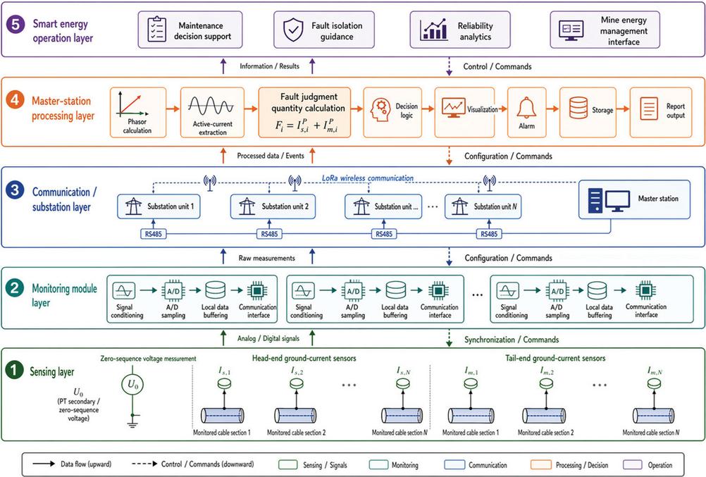
Figure 10 Smart monitoring system architecture.
7.2 Ground-Current Monitoring Module Installation
Figure 11 shows the installation arrangement of the double-ended ground-wire current monitoring modules. For each monitored cable section, one ground-current sensor is installed at the head end and the other at the tail end. The sensors are placed on the grounding conductor connected to the cable metallic shield, armor layer, or grounding busbar, so that the measured current reflects the fault-current distribution in the cable grounding path. The zero-sequence voltage is obtained from the PT secondary side at an accessible substation, distribution room, or switch station and is used as both the ground-fault trigger and phase reference.
A critical installation requirement is consistent sensor polarity. Because the proposed criterion is based on the algebraic summation of the active current components measured at the two ends of a cable section, reversed sensor orientation may lead to an incorrect fault judgment quantity. Therefore, the installation direction of all monitoring modules should be standardized and verified during commissioning, for example by applying or recording a known current direction. With consistent polarity, the double-ended measurements enable reliable calculation of the active ground-wire current summation for section-level fault location.
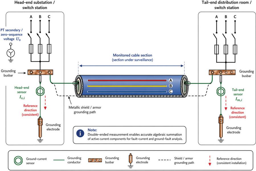
Figure 11 Installation arrangement of double-ended ground-wire current monitoring modules.
During commissioning, the polarity of each ground-current sensor can be verified by injecting a known low-magnitude test current through the grounding conductor or by recording a controlled switching or test event with known current direction. The measured current sign from all monitoring modules is then compared with the predefined reference direction. If a reversed polarity is detected, the installation direction can be corrected physically, or the polarity coefficient can be corrected in the master-station configuration. This step is important because an incorrect polarity setting may convert the intended active-current summation into a subtraction, resulting in missed detection or false location.
7.3 Data Acquisition and Communication Workflow
The data acquisition workflow begins when the master station sends a sampling command to the substations. After receiving the command, each substation transmits the acquisition instruction to its connected monitoring modules through RS485 communication. The monitoring modules then sample the ground-wire current signals and return the data to the substation. The substation packages the data and sends them to the master station through the LoRa wireless network.
Because the active current is calculated as the projection of the ground-wire current phasor onto the zero-sequence voltage phasor, phase accuracy is important. Two implementation approaches can be used. In the first approach, the master station issues a coordinated sampling command and all monitoring modules sample within a predefined time window. The sampled waveforms are then time-stamped and processed centrally. In the second approach, each local module calculates the current phasor using a synchronized time reference and uploads the phasor result to the master station. In both cases, the acceptable synchronization error should be selected according to the fundamental frequency and the required active-current accuracy. If the time deviation is excessive, the calculated active component may contain phase error, and the system should report a data-quality warning rather than issuing an automatic location result.
At the master station, the uploaded measurements are processed according to the algorithm described in Section 4. The zero-sequence voltage is first checked against the ground-fault trigger threshold. If a ground fault is detected, the system calculates the voltage and current phasors, extracts the active current components, computes the fault judgment quantity for each cable section, and identifies the fault location according to the decision logic.
This distributed workflow reduces the amount of processing required at each monitoring module while allowing the master station to perform global fault-location analysis across the monitored network. It also supports data storage and event review, which are important for maintenance, fault analysis, and long-term reliability evaluation.
7.4 Hardware and Communication Functions
The main hardware and communication functions of the monitoring system are summarized in Table 10. The monitoring modules focus on local current acquisition, while the substations coordinate communication with multiple monitoring modules. The master station performs the centralized fault-location calculation and provides the human-machine interface.
Table 10 Hardware and communication functions of the monitoring system
| Component | Main Function | Data or Signal Handled |
| Ground-current sensor | Measures current in the cable grounding path | , |
| Zero-sequence voltage input | Provides fault trigger and phase reference | |
| Monitoring module | Performs current signal acquisition and local data buffering | Sampled ground-wire current |
| RS485 communication link | Transfers data between monitoring modules and substations | Local monitoring data |
| Substation unit | Collects data from multiple monitoring modules and packages data for upload | Multi-point current data |
| LoRa communication link | Transfers data between substations and the master station | Packaged monitoring data |
| Master station | Performs calculation, display, storage, alarm, and reporting | Fault-location result and event records |
| Human-machine interface | Supports operator review and maintenance decision-making | Alarm, waveform, location, and history data |
7.5 Integration with Smart Mine Energy Monitoring
Beyond individual fault-location events, the proposed monitoring system can provide a data foundation for smart operation of underground mine distribution systems. The recorded ground-current waveforms, active-current components, fault judgment quantities, and alarm records can be used for reliability analysis, maintenance planning, and abnormal grounding-condition detection. When integrated with a mine energy management platform, the system can support faster fault isolation, reduced outage duration, and improved operational resilience.
This capability is closely aligned with the scope of smart local energy systems. Underground mine power networks are industrial local energy systems with strict reliability and safety requirements. By combining distributed sensing, communication, and centralized analytics, the proposed system supports the transition from passive fault response to active smart monitoring. As a result, the method not only improves fault-location accuracy, but also contributes to intelligent demand-side energy infrastructure and reliable operation of underground industrial distribution networks.
7.6 Practical Considerations and Smart Energy Relevance
Although the proposed method shows clear section-level selectivity in simulation, several practical factors should be considered during deployment. First, the polarity and installation direction of the ground-current sensors must be consistent across all monitored cable sections, because the fault judgment quantity is based on the algebraic summation of the head-end and tail-end active current components. Second, the threshold should be calibrated according to cable parameters, grounding resistance, background leakage current, current-transformer error, and monitoring-device calculation error. This calibration is important because non-faulted cable sections may still produce small residual values due to distributed capacitance and measurement uncertainty. Third, the communication system should support reliable data transfer, time coordination, and data-quality checks, especially in underground mine environments where wireless propagation and equipment accessibility may be challenging.
From a system-level perspective, the proposed monitoring architecture can contribute to smart operation of underground mine distribution networks. By rapidly identifying the faulted cable section or distinguishing a terminal busbar/switchgear fault, the system can reduce fault searching time, support faster isolation, and improve power supply continuity. The recorded ground-current waveforms, active-current components, fault judgment quantities, and alarm records can also provide useful information for maintenance planning, grounding-condition assessment, and long-term reliability analysis. Therefore, the proposed method is not only a fault-location technique, but also a practical monitoring component for intelligent demand-side energy infrastructure and resilient smart local energy systems in underground industrial applications.
8 Conclusion
This paper proposed a ground-wire active-current based fault-location method for smart monitoring of underground mine cable distribution systems. The method uses double-ended ground-wire current measurements and zero-sequence voltage as the phase reference to extract the active current components at both ends of each monitored cable section. Based on the directional distribution of fault current in the grounding network, a fault judgment quantity was constructed by summing the head-end and tail-end active current components.
Theoretical analysis showed that, for non-faulted cable sections, the active ground-wire current mainly behaves as through-current and is largely cancelled by the double-ended summation. In contrast, for the faulted cable section, the fault current flows from the fault point toward both ends, resulting in a dominant active-current summation. This difference provides the basis for section-level fault location.
Simulation results verified the effectiveness of the proposed method under different transition resistances from 0 to 1000 . The faulted cable section was correctly identified in all internal cable-fault cases, and terminal busbar/switchgear faults were distinguished without falsely identifying a healthy cable section. The results also showed that the fault-location margin remained well above the detection threshold under high-resistance fault conditions.
A distributed smart monitoring architecture was further presented, integrating ground-current sensors, zero-sequence voltage measurement, monitoring modules, RS485/LoRa communication, and master-station processing. From a practical operation perspective, the proposed method can reduce manual fault-searching time by narrowing the fault to a specific monitored cable section or terminal area. This capability is especially valuable in underground mine environments, where cable routes are difficult to access and prolonged fault isolation may affect ventilation, drainage, transportation, and production continuity. The method is therefore suitable not only as a protection-support technique, but also as a smart monitoring function for maintenance planning and resilient mine energy operation. The proposed method therefore provides a practical and interpretable solution for online fault location, faster fault isolation, and improved reliability of underground mine local energy distribution systems.
References
[1] C. Rae, S. Kerr, and M. M. Maroto-Valer, “Upscaling smart local energy systems: A review of technical barriers,” Renewable and Sustainable Energy Reviews, vol. 131, 110020, 2020.
[2] G. Chicco and P. Mancarella, “Distributed multi-generation: A comprehensive view,” Renewable and Sustainable Energy Reviews, vol. 13, no. 3, pp. 535–551, 2009.
[3] A. T. Dahiru, H. A. Ismail, A. R. Mohamed, and M. A. M. Radzi, “A comprehensive review of demand side management in renewable energy-based distributed grids,” Renewable and Sustainable Energy Reviews/open-access review literature, 2023.
[4] M. Ratshitanga, E. Orumwense, S. Krishnamurthy, and M. Melamu, “A review of demand-side resources in active distribution systems: Communication protocols, smart metering, control, automation, and optimization,” Applied Sciences, vol. 13, no. 23, 12573, 2023.
[5] J. De La Cruz, M. K. T. Al-Nussairi, and J. C. Vasquez, “Fault location for distribution smart grids: Literature overview, challenges, solutions, and future trends,” Energies, vol. 16, no. 5, 2280, 2023.
[6] I. Hamdeen, A. S. Al-Sumaiti, and M. A. Hannan, “Self-healing multi-agent techniques in electric power distribution systems: A review,” Renewable and Sustainable Energy Reviews, 2025.
[7] J. Roberts, H. J. Altuve, and D. Hou, “Review of ground fault protection methods for grounded, ungrounded, and compensated distribution systems,” Schweitzer Engineering Laboratories technical paper, 2001.
[8] Y. Gong, “A new ground fault detection method in three-wire distribution systems to reduce fire hazards,” Western Protective Relay Conference, 2024.
[9] S. Su, J. Wang, and X. Liu, “A single-phase grounding fault line selection method for flexible grounding systems based on the ratio of zero-sequence current changes,” IET Electric Power Applications, 2025.
[10] Q. Lian, Y. Zhang, and H. Wang, “ResNest-SVM-based method for identifying single-phase grounding faults in active distribution networks,” Frontiers in Energy Research, vol. 12, 1501737, 2024.
[11] IEEE Power & Energy Society, “IEEE Guide for Determining Fault Location on AC Transmission and Distribution Lines,” IEEE Std C37.114-2014, 2015.
[12] X. Yang, M.-S. Choi, S.-J. Lee, C.-W. Ten, and S.-I. Lim, “Fault location for underground power cable using distributed parameter approach,” IEEE Transactions on Power Systems, vol. 23, no. 4, pp. 1809–1816, 2008.
[13] E. Personal, A. García, A. Parejo, D. F. Larios, F. Biscarri, and C. León, “A comparison of impedance-based fault location methods for power underground distribution systems,” Energies, vol. 9, no. 12, 1022, 2016.
[14] W. Huo, Y. Zhang, and T. Li, “Fault location of cable hybrid transmission lines based on traveling wave energy,” Scientific Reports, vol. 12, 2022.
[15] N. Bayati, L. K. Mortensen, and M. H. S. Savaghebi, “A localized transient-based fault location scheme for distribution systems,” Sensors, vol. 22, no. 7, 2723, 2022.
[16] M. Santos, J. D. Melo, and A. G. Exposito, “Dynamic simulation of induced voltages in high voltage cable sheaths: Modeling and simulation,” International Journal of Electrical Power & Energy Systems, vol. 105, pp. 514–524, 2019.
[17] Z. Tan, X. Wang, and L. Zhang, “Research on SSTDR-based online distance measurement for cable fault location,” Academic Journal of Engineering and Technology Science, 2022.
[18] S. Barakat, M. Eteiba, and W. I. Wahba, “Fault location in underground cables using ANFIS nets and discrete wavelet transform,” Journal of Electrical Systems and Information Technology, vol. 1, no. 3, pp. 198–211, 2014.
[19] C. Wang, Y. Li, and X. Zhang, “A method for single-phase ground fault section location in distribution networks based on improved empirical wavelet transform and graph isomorphism networks,” Information, vol. 15, no. 10, 650, 2024.
[20] X. Wan, Y. Chen, and J. Li, “Single-phase ground fault detection method in three-phase four-wire distribution systems,” Electronics, vol. 14, no. 18, 3659, 2025.
[21] M. Fan, H. Zhang, and Y. Liu, “Single-phase grounding fault types identification based on transient zero-sequence current features,” Sensors, vol. 22, no. 10, 2022.
[22] D. Xiao, H. He, and X. Chen, “Segment location for single-phase-to-ground fault in neutral non-effectively grounded system based on distributed electric-field measurement,” Electric Power Systems Research, vol. 188, 106586, 2020.
[23] C. F. Jensen, O. M. K. K. Nanayakkara, A. D. Rajapakse, U. S. Gudmundsdottir, and C. L. Bak, “Online fault location on AC cables in underground transmission systems using sheath currents,” Electric Power Systems Research, vol. 115, pp. 74–79, 2014.
[24] M. Todorovski and R. Ackovski, “Equivalent circuit of single-core cable lines suitable for grounding systems analysis under line-to-ground faults,” IEEE Transactions on Power Delivery, vol. 29, no. 2, pp. 751–759, 2014.
[25] E. H. Ball, E. Occhini, and G. Luoni, “Sheath overvoltages in high-voltage cables resulting from special sheath-bonding connections,” IEEE Transactions on Power Apparatus and Systems, vol. PAS-84, no. 10, pp. 974–988, 1965.
Biographies

Mingzhen Zhang received the B.E. degree in Electronic and Computer Engineering from the University of Limerick in 2020, and M.S. degree in Electronic and Computer Engineering from the University of Birmingham in 2021. He is currently pursuing the Ph.D. degree with Huazhong University of Science and Technology, China. His current research interests include autonomous driving, electric vehicle, motion control, and nonlinear system.

Haipeng Huang, male, born in Ningxia in May 1988. He earned his bachelor’s degree and master’s degree in Mining Engineering from North China Institute of Science and Technology and Xi’an University of Science and Technology respectively. He is engaged in technical management of coal mine production.
Distributed Generation & Alternative Energy Journal, Vol. 41_4, 1113–1152
doi: 10.13052/dgaej2156-3306.41410
© 2026 River Publishers