Numerical Investigation of Ferrofluid Sloshing by Applying MHD Magnetic Field: Using Level Set Method
Rasool Maroofiazar1, Mohammad Daryani2,* and Amir Reza Vakhshouri3
1Department of Mechanical Engineering, Faculty of Engineering, University of Maragheh, Maragheh, Iran
2Faculty of Chemical Engineering, Sahand University of Technology, Sahand New Town, Tabriz, Iran
3Chemical Engineering Department, Baku Higher Oil School, 30 Khojali Ave., Baku, Azerbaijan
E-mail: Maroofiazar@maragheh.ac.ir; m_daryani@sut.ac.ir; amir.vakhshouri@bhos.edu.az
* Corresponding Author
Received 20 September 2019; Accepted 25 October 2019; Publication 07 November 2019
Abstract
The sloshing phenomenon has exceptional significance due to its occurrence in various processes as well as its application. This phenomenon occurs when a vessel is partly filled with a fluid and under the influence of external forces the free surface of the liquid moves and exchanges forces with the wall of the vessel. In this research, numerical modeling is used to study the behavior of ferrofluid in sloshing phenomenon in a rectangular container with a specified length and width of 10 cm × 5 cm respectively. The force that moves the vessel is the oscillatory motion in the x-axis direction. Applying a uniform magnetic force, which creates additional modules in the governing equations, such as the momentum equation, has effects on this phenomenon and fluid motion. The main aim of this research is to study the effects of the uniform MHD field in different directions and angles on the ferrofluid sloshing. By studying the results of some factors (such as; the pressure of the ferrofluid to the specific points on the vessel wall, the maximum surface at any time, and the analysis of the surface situation at different times) the impact of the magnetic field with different angles has been identified on the ferrofluid sloshing. The results showed that in the absence of an external magnetic field, the sloshing behavior of water and ferrofluid were approximately the same. Applying the MHD magnetic field caused a 14.5%, 25% and 36% decrease in the maximum height of the fluid level at angles 0°, 45° and 90° of magnetic field respectively. Therefore, these results indicate the influence of the magnetic field direction on the behavior of the ferrofluid sloshing.
Keywords: Sloshing, Ferrofluid, MHD, pressure, Level set method.
Nomenclature
| L | Length of the vessel (m) |
| W | Height of vessel (m) |
| g | Gravity (m/s2) |
| h | Fluid height (m) |
| V | Fluid velocity (m/s) |
| u | Fluid velocity in x direction (m/s) |
| v | Fluid velocity in y direction (m/s) |
| B | Magnetic induction (T) |
| H | Magnetic field intensity (A) |
| T | Temperature (°C) |
| n | Normal vector |
| k | Local curvature |
| A | Oscillation amplitude (m) |
| ωT | Oscillation frequency (Hz) |
| N | Frequency mode number |
| p | Pressure (pa) |
| t | Time (s) |
Greek Symbols
| ρ | Density of fluid (kg/m3) |
| μ | Dynamic viscosity (kg/ms) |
| μ0 | Permeability of vacuum (= 4π × 10−7 (Tm/A)) |
| α | Volume fraction of fluid |
| ∅ | Volume fraction of nanoparticles |
| σ | Effective electrical conductivity (1/Ωm) |
| τ | Non-dimension time |
Subscripts
| P | Point |
| f | Fluid |
| s | Solid |
| nf | Nanofluid |
| L | Liquid phase |
| G | Gas phase |
| deg | degree |
| MHD | Magneto-hydrodynamics |
1 Introduction
The sloshing phenomenon occurs in different parts and may have different applications. The Study and evaluation of the sloshing phenomenon in the transport sector is very momentous. The dynamics of solids’ bodies containing fluids has been widely developed due to its remarkable importance for the rockets and space industries [1]. Studies of this phenomenon are mostly used to predict the amount of fluid oscillations, stress on the walls, and the stability of the vessel milieu. Therefore, various experimental methods or numerical models have been developed [2].
Singal et al. [3], in their numerical research, adopted the volume of fluid model (VOF) to study the effects of sloshing on a kerosene container. They carried out experiments on the existence and absence of baffles, and discovered the significant effects of baffles. Also in other research, the optimum design of baffles were investigated numerically for increasing the rollover stability of the partially filled tankers with different shapes [4]. The effect of tank fill levels on sloshing measured in term of horizontal force and pressure moment were reported using the volume of fluid (VOF) method. Another study has been reported in both experimental and numerical methods by Takabatake et al. [5]. In this research, the effect of separator sheets and their positive performance in decreasing the sloshing height has been discussed. Uras, by using a computer modeling method studied the effect of viscosity on containers in the presence of a high viscous fluid [6]. A regular horizontal oscillation was considered as an external stimulation. The enforced pressure to the different points of the container and the height of the fluid wave were determined. It was found that the responses to time became faster to the steady state with increasing viscosity.
In several studies on various parameters, one of the substantial issues is the geometry of the vessels containing the fluid, which is encouraged by external forces. Among the types of geometries, Zeng et al. studied annulus geometry [7]. The purpose of this study was to investigate the sloshing phenomenon on a large water tank as well as to simulate critical conditions such as earthquakes. The researchers calculated the impact pressure at various points of the tank to obtain effective results.
One of the vital variables considered to investigate this phenomenon is magnetic fluids. Sawada et al. studied magnetic fluid sloshing inside a cylindrical vessel in the laboratory scale [8]. For precise investigation, the difference between the presence and absence of magnetic field has been investigated. As results, the spatial velocity of the fluid has been determined and the effect of the magnetic field on fluid has been presented.
One of the most reliable applications of this phenomenon is the electrical energy harvesting using ferrofluids and magnetic field. Several investigations have been carried out in both laboratory and numerical methods by various parameters in order to optimize and enhance energy harvesting. Consequently, in a container with different geometries, electric power can be generated by using ferrofluids, magnetic field and effective external force. This project is imperative because of its advantages such as being flexible and scalable in energy production [9–11].
The effects of MHD magnetic field have been extensively studied on the flow and heat transfer of nanofluids (e.g., [12–14]). In the meantime, it can be mentioned to the study of nanofluid flow behavior between two radiative stretchable rotary disk that has been investigated with homogeneous and heterogeneous reactions and Joule heating in the presence of magnetic field [15]. In another study, analysis for micropolar dusty fluid containing hybrid nanoparticles has been investigated over a porous medium [16]. The effect of Brownian motion, thermophoresis phenomenon and Lewis number on MHD nanofluid flow along with the heat transfer between two parallel plates have also been studied [17].
Ferrofluids are a special type of nanofluids that could be synthesized using a colloidal mixture of magnetic nanoparticles and a non-magnetic carrier fluid [18]. Gholinia et al. have studied nanofluids in various fields of fluid flow and heat transfer [19]. Ghadikolaei et al. in their study, have proposed an analysis of three-dimensional squeezing flow of carbon nanotubes (CNTs) based nanofluids in a rotating channel with a permeable fixed bottom wall by taking into account the effect of thermal radiation [20]. These authors also presented in another article, the increase of fluid heat transfer by application of hybrid nanoparticles [21]. In this study, nanofluids were prepared by dispersion of Fe3O4 nanoparticles (0.04 and 4%) in water as a base fluid. The physical properties of the nanofluid are presented in Table 1. Castillo et al. [22] used Level Set method to modeling and numerically solution of two immiscible fluids, which makes it possible to more accurately analyze the work. In this research, this method has also been used. The accuracy of numerical computations of this study has been validated by the results of an experimental-based research [23]. The results for the prepared ferrofluids, including recordings of pressure at different points on the rectangular vessel wall, recording of maximum height, fluid surface conditions versus times, as well as the results of applying MHD magnetic field in different directions were collected and compared. As a result, the effect of uniform magnetic field orientation on the ferrofluid sloshing was discussed.
Table 1 Physical properties of water and nanoparticles and ferrofluid [29]
| ρ(kg/m3) | μ × 10−4(kg/(m · s)) | σ(1/(Ω · m)) | |
| Pure water | 997.1 | 8.55 | 0.050 |
| Fe3O4 | 5200 | – | 25000 |
| 4% Ferrofluid | 1165.22 | 941 | 0.056 |
2 Mathematical Modeling
In this paper, 3D geometry has firstly been considered and then compared with the results of 2D geometry (Figure 1). After the accuracy of the results have been verified, the rest of the studies were performed in 2D geometry. The external stimulation of the vessel was accomplished sinusoidal in the x direction and the results were recorded according to the conditions described in the formulation section related to the vessel movement.
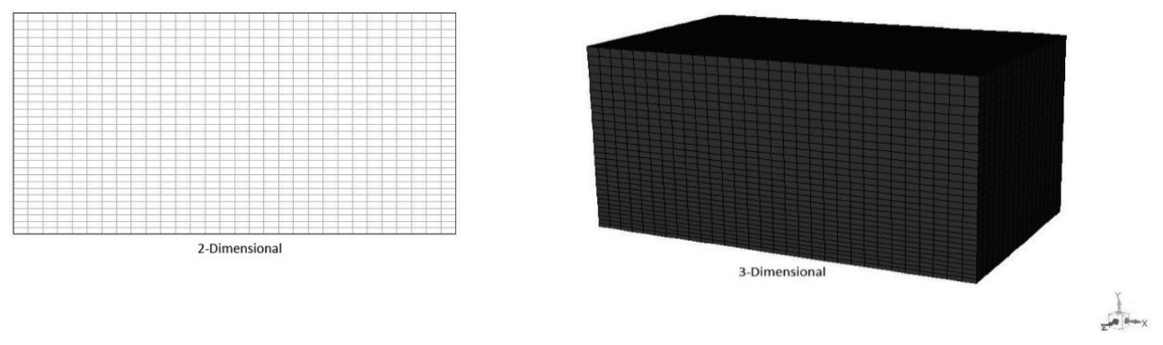
Figure 1 Geometry of two dimensional and three dimensional modeling.
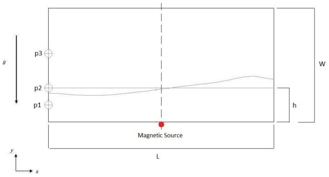
Figure 2 Geometry and boundary conditions, pressure recording points, and magnetic source location.
The specific physical properties of ferrofluid were obtained by adding 4% of Fe3O4 nanoparticles to the base fluid. The magnetic field was supplied using a conductive wire in the middle-bottom of the vessel, which was placed perpendicular to the x−y plane (Figure 2).
2.1 Governing Equations
In this modeling, some assumptions for fluid dynamics including Newtonian, incompressible and non-elastic fluid with laminar flow range neglected turbulence, as well as two immiscible fluids in an unsteady state and isothermal process have been considered. Based on these assumptions, the governing equations have been studied. For that reason, the governing equations could be the continuity and momentum equations, which are written below [18, 24, 25]. If the MHD magnetic field is applied, a new term in the form of Lorentz force will be added to the momentum equation. Therefore, Equations (2) and (3) are related to the ordinary fluid whereas Equations (4) and (5) associated with the ferrofluid, which are expressed in the Cartesian coordinate system. Hence, the set of governing equations describing MHD is a combination of Navier Stokes fluid dynamics equations and Maxwell’s electromagnetic equations. These equations must be solved simultaneously [26–28].
Continuity equation:
| (1) |
Momentum equation for ordinary fluid in x direction:
| (2) |
Momentum equation for ordinary fluid in y direction:
| (3) |
Momentum equation for ferrofluid with MHD field in x direction:
| (4) |
Momentum equation for ferrofluid with MHD field in y direction:
| (5) |
In Equation (1), V is the component of corresponding velocity of fluid. In Equations (2) and (3) (ρ = αρ1 + (1 − α)ρ2) is the mixture density of liquid and air, ρ1 and ρ2 are the density of fluid and air, respectively, and (μ = αμ1 + (1 - α)μ2) is the viscosity of the mixture. α Expresses the volume fraction of fluid that is 1 for liquid, and 0 for the air, the area between them being between 0 and 1. p is pressure and gy shows the effect of gravity in the y direction.
The terms and in (4) and (5), respectively, appear as a result of the electrical conductivity of the fluid and denote the Lorentz force per unit volume in the x and y directions which highlights the principles of MHD. B is the magnetic induction that defined by the following equation:
| (6) |
μ0 is the magnetic permeability of vacuum (4π × 10−7Tm/A); H is the magnetic field intensity. For the variation of the magnetization (M) as a function of the magnetic field intensity (H) and temperature (T), the subsequent correlation can be assumed as [26];
| (7) |
The magnetic field was supplied by a wire perpendicular to the x − y plane in the middle-bottom of the container (Figure 2). The magnitude of the magnetic induction was assumed B = 1T that was examined at three angles of 0°, 45°, 90°. The concept of angles in the MHD magnetic field is to determine the direction and angle of the field lines. When the magnetic induction angle is set to 0°, it means that the field lines are in a horizontal state, which, by increasing this angle, moves from a horizontal state to a vertical position at 90°. The imposed magnetic field B = 1T, by considering the relation of the magnetic field angles, was determined by the following equation.
| (8) |
The ferrofluid used as the model in this study consists of 4% volume of Fe3O4 nanoparticles where the following correlations have been used to calculate the physical properties of ferrofluid:
| (9) |
The dynamic viscosity of the nanofluid given by Brinkman [26] is:
| (10) |
The effective electrical conductivity (σnf) of the nanofluid can be calculated by Maxwell’s approximate:
| (11) |
The physical properties of the ferrofluid, pure water as the base fluid and Fe3O4 nanoparticles are given in Table 1.
2.2 Level Set Method
This model has been used to record large changes in the pressure of two-phase fluids. The fluid level is considered as the initial level and indicated by φ as the distance function [30].
| (12) |
The level set equation is solved in the entire computational domain. This includes the fluid and solid areas, which progress to re-initialize the level set function in a repetitive manner to keep the distance function to the answer.
| (13) |
| (14) |
In the above equations, τ is reflected as non-dimension time, φ0 the initial value of φ and Δh is very small amount in this model φ is considered as a function of distance, Therefore, two parameters of the unit normal vector (n) and the local curvature (k) for the common level can be calculated with finite differential equations:
| (15) |
| (16) |
Density and viscosity are adjusted all over the common surface with the smoothed Heaviside function. They are corrected on a transmission bar throughout the common surface:
| (17) |
L and G represent the liquid phase and the air, respectively. The smoothed Heaviside function is defined as [31, 32]:
| (18) |
2.3 Vessel Movement Formulation
In this research, the external stimulation of the vessel is described as a horizontal sinusoidal motion in the x direction with specific amplitudes and frequencies. The equation of motion follows the below relation:
| (19) |
In the above equation A and ωT are the oscillation amplitude and frequency, respectively. In this study, the range of stimulation for a rectangular vessel is assumed to be where, L is the length of the vessel. If the dimensions of the vessel and the height of the fluid are determined, the natural frequency ωT can be expressed by the following expression [30]:
| (20) |
Here, L represents the vessel length; h is the fluid height and N is the frequency mode number [26].
3 Results and Discussions
3.1 Geometry Selection and Validation
In the first step, modeling was conducted in 3D geometry. The dimensions of the assumed vessel were 10 cm × 5 cm × 5 cm, which shows length, width and height, respectively. Considering the ratio of , the simulation was performed for 3D and 2D models (Figure 1), and then the results were compared. After the results of 3D and 2D were matched (Figure 3), the investigation continued in 2D mode. In order to stimulate sinus oscillation, the vessel has been used in the first mode number (ω1) and studies have been proceeded accordingly.
As mentioned, to ensure the accuracy of the numerical calculations, a comparison was made between the results of the numerical simulation and the results of an experimental work [23] (Figure 4). It can be observed that there was a proper match between the results.
The results were recorded as the imposed pressure by the ferrofluid to points on the container wall called points P1, P2 and P3. Additionally, the maximum change in nanofluid level occurring at any time was also recorded. By analyzing these results, the effect of the MHD magnetic field with different induction magnitude and different induction angles could be determined.
The points of the pressure recording have been selected in the static state without motion of vessel. In this case, P1, P2 and P3 were located below the fluid-air interface (h = 0.75 cm), at the fluid-air interface (h = 1.5 cm), and at the top of the fluid-air cross-section (h = 3 cm), respectively.
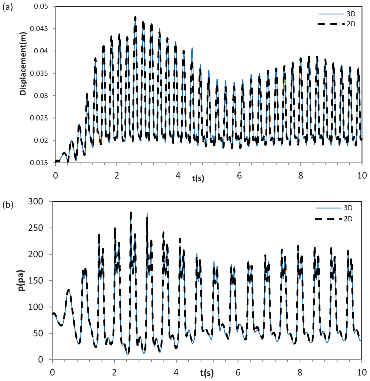
Figure 3 Comparison of the 3D and 2D models for the ferrofluid in B = 0, the displacement of the maximum height (a) and the pressure applied to the point P1 (b).
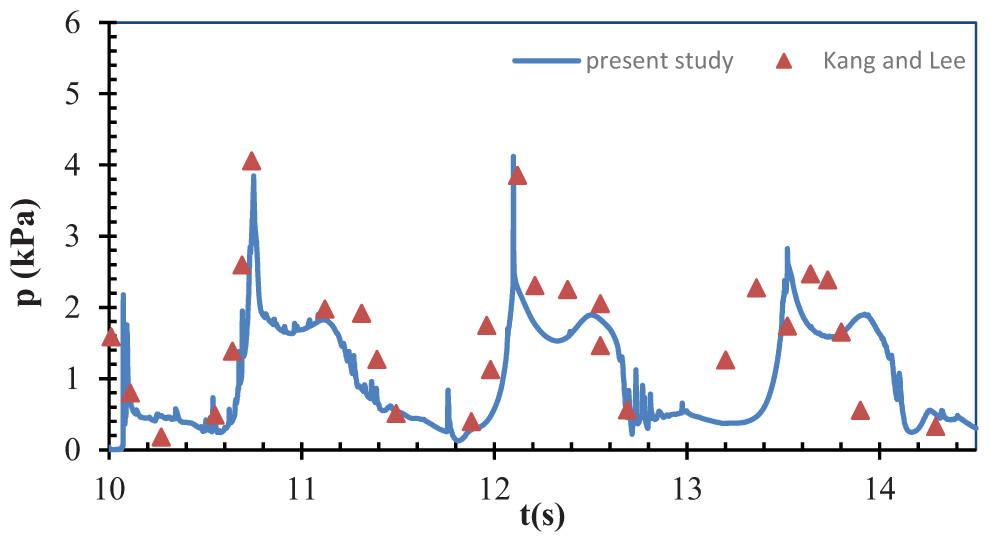
Figure 4 Validation with experimental-based research [23].
3.2 Sloshing without Magnetic Field
The results of ferrofluid sloshing were firstly investigated without applying the magnetic field. It was observed that when the magnetic field was not employed, the ferrofluid behavior was similar to that of the base fluid, and no significant changes were observed (Figure 5). Then, when the magnetic field is applied, magnetic and hydrodynamic behaviors must be considered simultaneously.
3.3 Effect of Magnetic Field on Sloshing
Effect of magnetic field on the maximum level changes and the imposed pressure to the specified points of the vessel are presented in Figure 6.

Figure 5 Comparison of the water and ferrofluid sloshing in B = 0, (a) the displacement of the maximum height and (b) the pressure applied to the point P2.
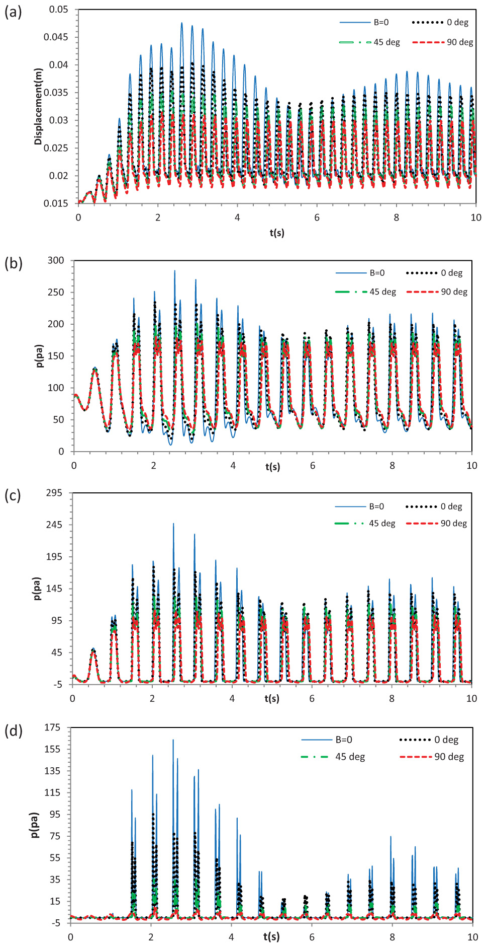
Figure 6 Comparison of the ferrofluid sloshing with imposed MHD field in B = 1 and with magnetic lines angles of 0°, 45° and 90°. The displacement of the maximum height (a), the enforced pressure to the point P1 (b), the enforced pressure to the point P2 (c) and the enforced applied to the point P3 (d).
Table 2 The amount of pressure reduction according to maximum pressure up to ten seconds
| P1 | P2 | P3 | ||
| B = 0 | 285 pa | 250 pa | 165 pa | |
| Reduction Percent | (B = 1) 0° | 15.5% | 28% | 42% |
| (B = 45) 0° | 26% | 46% | 75% | |
| (B = 1) 90° | 40% | 56% | 90% |
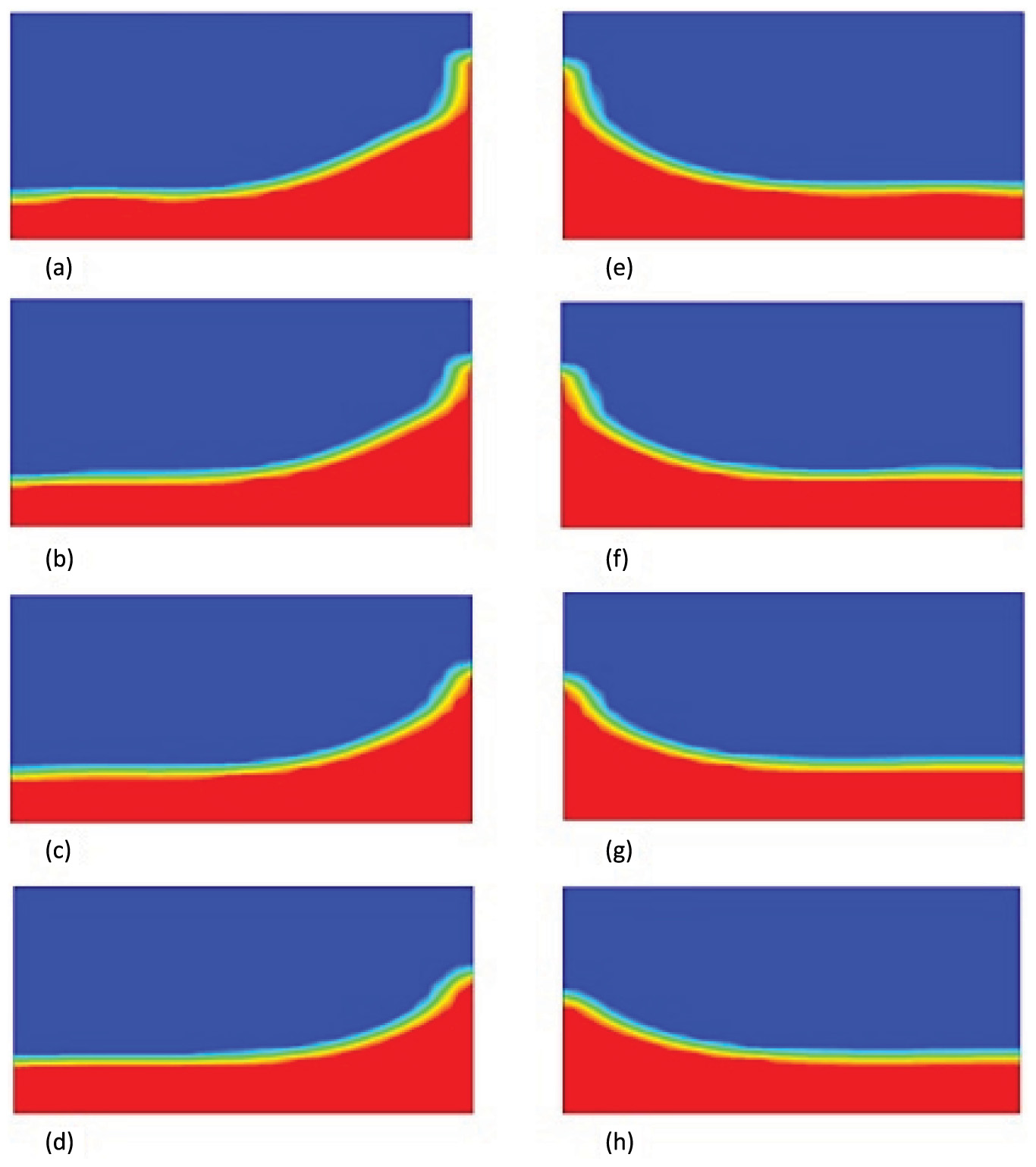
Figure 7 Position of free surface at t = 2.9 s (left graphs) with conditions; B = 0 (a), B = 1 with magnetic lines angles of θ = 0° (b), θ = 45° (c) and θ = 90° (d). Likewise, at t = 8 s (right graphs) with conditions; B = 0 (e), B = 1 with magnetic lines angles of θ = 0° (f), θ = 45° (g) and θ = 90° (h).
As seen from Figure 6, using the magnetic field reduced both the maximum surface level displacement of the fluid and the applied pressure at the specified points in the container. For example, in the horizontal magnetic field the maximum height displacement of the fluid in the container was 14.5% lower than the cases without magnetic field.
Changing the magnetic field angle from 0° to 90°, the sloshing parameters were more influenced by the magnetic field. It can be observed that increasing the magnetic field angle caused a 25% and 36% reduction in the maximum level displacement of the fluid for 45° and 90° of magnetic field lines, respectively. The reason of these findings can be discussed as follows. By applying the magnetic field, an external force called the Lorentz force, was applied to the fluid in the container and restricted its motion and sloshing. In the magnetic field with horizontal lines, this force exerts horizontally and by increasing its angle, the direction of the Lorentz force was also changed and at the angle of 90°, its direction was pure vertical and more suppressed the fluid sloshing. Similar results and discussions can be mentioned for the pressure imposed on the specified point in the container. Summary of the results of the imposed pressure on the effect of applied magnetic fields are given in Table 2. Another important point that can be concluded from this table is that the imposed pressure on the points with higher heights were more influenced by the applied magnetic fields.
For visual observation of the effect of magnetic field on the sloshing of the ferrofluid, the contours of fluid motion at t = 2.9 s and t = 8 s has been recorded and was displayed in Figure 7.
4 Conclusions
- This model is associated with the level set method that accurately determines the interface between two phases at any given moment. By using this method, the effect of various parameters can be easily studied and in addition, it does not need to carry out expensive experimental methods.
- Since suitable conformity was observed between the three-dimensional and two-dimensional results; a complete analysis was carried out in two-dimensional mode in order to perform the numerical calculations more quickly.
- When ferrofluid sloshing was performed without applying a magnetic field, it was observed that ferrofluid behavior exhibited ordinary fluid and no significant changes occurred.
- Application of the magnetic field caused sensible reduction in sloshing of the ferrofluid due to the imposed force which is called the Lorentz force.
- Changing the angle of the field lines causes variations in ferrofluid behavior. According to the results, when the field is applied at 0°, (where, By = 0, Bx = 1 and the field lines are horizontal) it has the minimum effect on the ferrofluid motion inside the vessel. Whereas, by switching the field lines from zero to 90 degrees, which means that they are quite vertical for the field lines, it has the maximum impact on the ferrofluid sloshing.
- Displacement of the maximum surface of the fluid in the container was 14.5%, 25% and 36% lower than the no magnetic field case at 0, 45 and 90 degrees of magnetic field respectively.
- This method will help in selecting and controlling the desired state of ferrofluid motion in advancing the scientific, research and practical purposes of the sloshing phenomenon by changing the angle of the field lines which it has been achieved in a cost-effective and practical method.
References
[1] G. N. Mikishev and B. I. Rabinovich, “Dynamics of solid body with caverns partly filled with fluid (in Russian). Mashinostroenie, Moscow,” 1968.
[2] E. Oñate, S. R. Idelsohn, and R. Aubry, “Possibilities of the particle finite element method for fluid-structure interaction problems with free surface waves Possibilities of the particle finite element method for fluid-structure interaction problems with free surface waves,” Rev. Eur. des Éléments, no. October 2014, pp. 37–41, 2012. http://dx.doi.org/10.3166/reef.13.637-666
[3] V. Singal, J. Bajaj, N. Awalgaonkar, and S. Tibdewal, “CFD analysis of a kerosene fuel tank to reduce liquid sloshing,” Procedia Eng., vol. 69, pp. 1365–1371, 2014. https://doi.org/10.1016/j.proeng.2014.03.130
[4] S. Ali, M. A. Kamran, and S. Khan, “Effect of baffle size and orientation on lateral sloshing of partially filled containers: a numerical study,” Eur. J. Comput. Mech., vol. 7179, no. October, pp. 1–25, 2017. http://dx.doi.org/10.1080/17797179.2017.1386023
[5] D. Takabatake, S. Sawada, N. Yoneyama, and M. Miura, “Sloshing Reduction Effect Of Splitting Wall In Cylindrical Tank,” 14th World Conf. Earthq. Eng., 2008.
[6] R. A. Uras, “Sloshing analysis of viscous liquidstorage tanks,” Fluid-Sloshing Fluid-Structure Interact. ASME Press. Vessel. Pip. Conf, pp. 63–72, 1995. https://www.osti.gov/biblio/79730
[7] D. Lu, X. Zeng, J. Dang, and Y. Liu, “A calculation method for the sloshing impact pressure imposed on the roof of a passive water storage tank of AP1000,” Sci. Technol. Nucl. Install., vol. 2016, 2016. http://dx.doi.org/10.1155/2016/1613989
[8] T. Sawada, Y. Ohira, and H. Houda, “Sloshing motion of a magnetic fluid in a cylindrical container due to horizontal oscillation,” Energy Convers. Manag., vol. 43, no. 3, pp. 299–308, 2002. https://doi.org/10.1016/S0196-8904(01)00103-0
[9] A. Bibo, R. Masana, A. King, G. Li, and M. F. Daqaq, “Electromagnetic ferrofluid-based energy harvester,” Phys. Lett. Sect. A Gen. At. Solid State Phys., vol. 376, no. 32, pp. 2163–2166, 2012. https://doi.org/10.1016/j.physleta.2012.05.033
[10] S.Alazmi,Y. Xu, and M. F. Daqaq, “Harvesting energy from the sloshing motion of ferrofluids in an externally excited container: Analytical modeling and experimental validation,” Phys. Fluids, vol. 28, no. 7, 2016. https://doi.org/10.1063/1.4954787
[11] Q. Liu, S. F. Alazemi, M. F. Daqaq, and G. Li, “A ferrofluid based energy harvester: Computational modeling, analysis, and experimental validation,” J. Magn. Magn. Mater., vol. 449, pp. 105–118, 2018. https://doi.org/10.1016/j.jmmm.2017.09.064
[12] M. Hatami, K. Hosseinzadeh, G. Domairry, and M. T. Behnamfar, “Numerical study of MHD two-phase Couette flow analysis for fluid-particle suspension between moving parallel plates,” J. Taiwan Inst. Chem. Eng., 2014. https://doi.org/10.1016/j.jtice.2014.05.018
[13] K.Hosseinzadeh,A.Asadi,A.R.Mogharrebi,J.Khalesi,S.Mousavisani, and D. D. Ganji, “Entropy generation analysis of (CH2OH)2 containing CNTs nano fluid flow under effect of MHD and thermal radiation,” vol. 14, no. May, 2019. https://doi.org/10.1016/j.csite.2019.100482
[14] S. S. Ghadikolaei, K. Hosseinzadeh, and D. D. Ganji, “Numerical study on magnetohydrodynic CNTs-water nanofluids as a micropolar dusty fluid influenced by non-linear thermal radiation and joule heating effect,” Powder Technol., pp. 389–399, 2018. https://doi.org/10.1016/j.powtec.2018.09.023
[15] M. R. Zangooee, K. Hosseinzadeh, and D. D. Ganji, “Hydrothermal analysis of MHD nano fluid (TiO2-GO) flow between two radiative stretchable rotating disks using AGM,” Case Study Therm. Eng., vol. 14, no. May, p. 100460, 2019. https://doi.org/10.1016/j.csite.2019.100460
[16] S. S. Ghadikolaei, K. Hosseinzadeh, M. Hatami, and D. D. Ganji, “MHD boundary layer analysis for micropolar dusty fluid containing Hybrid nanoparticles (Cu-Al2O3) over a porous medium,” J. Mol. Liq., pp. 813–823, 2018. https://doi.org/10.1016/j.molliq.2018.07.105
[17] K. Hosseinzadeh, A. J. Amiri, S. S. Ardahaie, and D. D. Ganji, “Effect of variable lorentz forces on nanofluid flow in movable parallel plates utilizing analytical method,” vol. 10, no. March, pp. 595–610, 2017. https://doi.org/10.1016/j.csite.2017.11.001
[18] H.Aminfar, M.Mohammadpourfard, and R. Maroofiazar, “Experimental study on the effect of magnetic field on critical heat flux of ferrofluid flow boiling in a vertical annulus,” Exp. Therm. Fluid Sci., vol. 58, pp. 156–169, 2014. https://doi.org/10.1016/j.expthermflusci.2014.06.023
[19] M. Gholinia, S. Gholinia, K. Hosseinzadeh, and D. D. Ganji, “Investigation on ethylene glycol Nano fluid flow over a vertical permeable circular cylinder under effect of magnetic field,” vol. 9, no. May, pp. 1525–1533, 2018. https://doi.org/10.1016/j.rinp.2018.04.070
[20] S. S. Ghadikolaei, K. Hosseinzadeh, M. Hatami, D. D. Ganji, and M.Armin, “Investigation for squeezingflowof ethylene glycol (C2H6O2) carbon nanotubes (CNTs) in rotating stretching channel with nonlinear thermal radiation,” J. Mol. Liq., no. 2017, pp. 10–21, 2018. https://doi.org/10.1016/j.molliq.2018.04.141
[21] S. S. Ghadikolaei, K. Hosseinzadeh, and D. D. Ganji, “Investigation on ethylene glycol-water mixture fluid suspend by hybrid nanoparticles (TiO2-CuO) over rotating cone with considering nanoparticles shape factor,” J. Mol. Liq., pp. 226–236, 2018. https://doi.org/10.1016/j.molliq.2018.09.084
[22] E. Castillo, J. Baiges, and R. Codina, “Approximation of the two-fluid flow problem for viscoelastic fluids using the level set method and pressure enriched finite element shape functions,” J. Nonnewton. Fluid Mech., vol. 225, pp. 37–53, 2015. https://doi.org/10.1016/j.jnnfm.2015.09.004
[23] D. H. Kang and Y. B. Lee, “Summary report of sloshing model test for rectangular model,” Daewoo Shipbuild. Mar. Eng. Co., Ltd.
[24] J. Zhang, W. Wu, and J. Hu, “A numerical study of the effects of the longitudinal baffle on nickel ore slurry sloshing in a prismatic cargo hold,” Mar. Struct., vol. 46, pp. 149–166, 2016. https://doi.org/10.1016/j.marstruc.2016.01.003
[25] P. J. Oliveira, F. T. Pinho, and G. A. Pinto, “Numerical simulation of non-linear elastic flows with a general collocated finite-volume method,” J. Nonnewton. Fluid Mech., vol. 79, no. 1, pp. 1–43, 1998. https://doi.org/10.1016/S0377-0257(98)00082-2
[26] M. Sheikholeslami, K. Vajravelu, and M. Mehdi, “Forced convection heat transfer in a semi annulus under the influence of a variable magnetic field,” HEAT MASS Transf., vol. 92, pp. 339–348, 2016. https://doi.org/10.1016/j.ijheatmasstransfer.2015.08.066
[27] M. Sheikholeslami and M.M. Rashidi, “Ferrofluid heat transfer treatment in the presence of variable magnetic field,” The European Physical Journal Plus 2015. https://doi.org/10.1140/epjp/i
[28] M. Sheikholeslami et al., “Effect of a Magnetic Field on Mixed Convection of a Nanofluid in a Square Cavity,” vol. 18, no. 3, pp. 321–325, 2013. https://doi.org/10.4283/JMAG.2013.18.3.321
[29] D. D. Ganji. M. Sheikholeslami, M. M. Rashidi, “Effect of non-uniform magnetic field on forced convection heat transfer of Fe3O4-water nanofluid,” Comput. Methods Appl. Mech. Eng., 2015. https://doi.org/10.1016/j.cma.2015.06.010
[30] M. Sussman, P. Smereka, and S. Osher, “ALevel Set Approach for Computing Solutions to Incompressible Two-Phase Flow,” J. Comput. Phys., vol. 114, no. 1, pp. 146–159, 1994. https://doi.org/10.1006/jcph.1994. 1155
[31] S. Osher and J.A. Sethian, “Fronts propagating with curvature-dependent speed: Algorithms based on Hamilton-Jacobi formulations,” J. Comput. Phys., vol. 79, no. 1, pp. 12–49, 1988. https://doi.org/10.1016/0021-9991(88)90002-2
[32] Y. Lin, L. Zheng, and X. Zhang, “Radiation effects on Marangoni convection flow and heat transfer in pseudo-plastic non-Newtonian nanofluids with variable thermal conductivity,” Int. J. Heat Mass Transf., vol. 77, pp. 708–716, 2014. https://doi.org/10.1016/j.ijheatmasstransfer.2014.06.028
Biographies

Rasool Maroofiazar received his B.Sc., M.Sc. and Ph.D. degrees in Mechanical Engineering from University of Tabriz, Iran. Dr. Maroofiazar is currently an Assistant Professor at the Department of Mechanical Engineering at the University of Maragheh, Iran. His research interests include Energy Harvesting, Nanofluid Flow and Heat Transfer, Two-phase Flows, and Non-Traditional Machining.

Mohammad Daryani received his B.Sc. degrees in Chemical Engineering from Urmia University of Technology, Iran. He is currently studying a master’s degree in Chemical Engineering at Sahand University of Technology, Tabriz, Iran. His research interests include CFD and Transfer Phenomenon, Wastewater Treatment, Separation Processes and the Environment.

Amir Reza Vakhshouri received his B.Sc. degree in Applied Chemistry from University of Tabriz and his M.Sc. degree from Tabriz Azad University, Iran. He received his PhD degree in Polymer and Petroleum Chemistry at the Institute of Petrochemical Processes from Azerbaijan National Academy of Sciences. He is currently an Associate Professor at the Chemical Engineering Department of Baku Higher Oil School, Republic of Azerbaijan. His research interests include advanced nano-materials, thermal energy storage systems, environmental problems and multiphase thermodynamics.
European Journal of Computational Mechanics, Vol. 28_4, 351–372.
doi: 10.13052/ejcm1958-5829.2844
©2019 River Publishers