Analysis of Characteristics of Plastic Zone and Mechanical Properties of Anchor Structure in Hydraulic Tunnels with High Ground Temperature
Yuhang Huang and Haibo Jiang*
College of Water & Architectural Engineering, Shihezi University, Shihezi 832000, China
E-mail: klaud_123@163.com
*Corresponding Author
Received 02 December 2021; Accepted 15 December 2021; Publication 18 January 2022
Abstract
In order to explore the characteristics of plastic zone and the mechanical properties of anchor structure during the construction of hydraulic tunnels with high ground temperature, the high-temperature section of the diversion tunnel of a hydropower station in Xinjiang was studied. Based on the temperature data and the axial force data of the bolt on-site, the Drucker-Prager constitutive model and the finite element method were adopted to simulate and analyze the temperature-stress coupled field and the initial anchoring support during the construction of the high ground temperature tunnels. The results showed that, after the excavation of the tunnel, a crescent-shaped plastic zone first appeared at the hance, then expanded to the spandrel and vault, and finally formed an irregular ring-shaped plastic zone around the tunnel. The higher the initial temperature of surrounding rocks, the larger the plastic deformation and the range of the plastic zone. When the temperature exceeded 80C, the plastic zone was more likely to expand to the spandrel and vault; and meanwhile, when the bolt was closer to the hance, the neutral point was closer to the cavity wall. As the stress was released, the neutral point moved from close to the cavity wall to away from the cavity wall. Anchoring support can effectively limit the development of plastic zone in surrounding rocks under high ground temperature. After 10 days of anchoring support at 60C, 80C, and 100C, the range of the plastic zone decreased by 9%, 20%, 24%, respectively, and the maximum axial force of a single bolt was 19.4 kN, 20.1 kN, and 23.8 kN, respectively. The higher the temperature, the higher the strength of the bolt.
Keywords: High ground temperature tunnel, plastic zone, anchoring support, neutral point.
1 Introduction
With the implementation of the “One Belt One Road” initiative, many water conservancy, transportation, and mining projects need to be carried out in a complex geological environment with large burial depths and high ground temperatures. The redistribution of stress caused by tunnel excavation and the temperature stress caused by temperature change will inevitably lead to plastic deformation of surrounding rocks, thereby affecting the stability of the tunnel. In order to limit the deformation of surrounding rocks and improve the overall stability of the tunnel project, the initial anchoring support during the construction period can effectively increase the strength of the rock mass.
At present, many scholars in China and other countries have studied the initial support theory of underground engineering under a high ground temperature environment, and achieved some results in this field. For example, based on a large number of field tests, Wang Mingnian et al. [1, 2] put forward three types of temperature changes after the excavation of high ground temperature tunnels, i.e., fluctuating, descending, and stable type. Meanwhile, they analyzed the shear failure mode of the concrete interface, the peak shear strength of the interface, and the interface displacement under different temperatures, and proposed the concrete-rock interface shear constitutive model considering the temperature damage effect. Wu Di et al. [3] established a water-heat-stress coupled model of tunnel excavation through the combination of numerical simulation and model test, and obtained the stress and deformation characteristics of the tunnel after excavation. Su Guoshao et al. [4] established a water-heat-stress-damage coupled model through theoretical analysis and numerical simulation, and used the model evolution to analyze the influence of different factors on the bearing characteristics. Hu Yunpeng et al. [5] studied the mechanical properties and thermal damage model of the concrete spraying layer of the tunnel under a high-temperature environment through field tests and numerical simulations based on the Sangzhuling Tunnel. Li Fuhai et al. [6, 7] found the change law of the ultimate tensile force of the bolt under working load and curing temperature through the experiments with different models, and obtained the polynomial function to describe the influence of temperature and the roughness of surrounding rocks on the ultimate tensile force of the bolt. Yao Xianchun et al. [8] obtained the stress change characteristics of the support structure of the diversion tunnel under different surrounding rock temperature and water temperature through model tests, and used numerical simulation to verify the obtained relationship between the temperature difference between the inner and outer walls of the support structure and the internal temperature stress. Fan Lei [9] took the Gaoligongshan Tunnel as an example, determined the reasonable thermal hazard control standards and areas for underground engineering, proposed a tunnel support system under high ground temperature, and established a three-dimensional unsteady heat transfer model. Li Ming et al. [10] used the theory of elastoplastic mechanics to establish an analytical solution for the stress and displacement of surrounding rocks during tunnel construction, and combined it with actual engineering to propose different support plans for early excavation and after excavation. Yu Weijian et al. [11] studied the deformation characteristics of high-stress tunnels through on-site investigation, put forward a comprehensive support scheme and layer-built reinforcement method, and explored the method for checking the parameters of anchor cable and bolt.
Based on the above methods, scholars have studied the characteristics of stress and displacement of surrounding rocks during tunnel construction under high-temperature environments, proposed the methods of initial support of surrounding rocks as well as the effective research on maintaining the stability of surrounding rock, and achieved fruitful results. However, there are few studies on the performance of the plastic zone of surrounding rocks before and after anchoring support and the axial force of the bolt in the high ground temperature tunnel. Therefore, taking the high ground temperature hydraulic tunnel project of a hydropower station in Xinjiang as an example, this paper analyzed the measured data and numerical calculations to study the distribution characteristics of the plastic zone under the temperature-stress coupled effect in the high ground temperature tunnel and the mechanical characteristics of the anchoring support, which can provide a reference for other high ground temperature projects under similar conditions.
2 Field Monitoring Test of Diversion Tunnel with High Ground Temperature
2.1 Project Overview
According to the existing survey data, there is a high ground temperature section with a total length of about 4000 m in the front section of the hydraulic tunnel. The rock mass is composed of mica quartz schist interposed with graphite schist, the branch tunnel under construction is dry and no groundwater leakage is seen. During the tunneling process, the maximum ambient temperature of the tunnel face reached 67C, the maximum temperature in the hole reached 105C or above, and the water temperature during the operation period was as low as 0–5C. The depth of burial in each section of the project varies greatly. The high ground temperature is caused by uneven heat conduction; except for the high temperature, it also covers a wide range, which is rare in China and other countries.
In order to explore whether the supporting structure of the high-temperature hydraulic tunnel of the hydropower station is safe during the construction and the effect of the supporting measures, a test tunnel was designed in the main tunnel to monitor the temperature of surrounding rocks and the stress of the supporting structure during the construction of the test tunnel. Through systematic analysis of the monitoring data, we obtained the characteristics and mechanism of the surrounding rock temperature and the stress change of the supporting structure during the construction of the high-temperature tunnel. In addition, the mechanical properties of surrounding rocks and supporting structure were comparatively analyzed to provide a reference for the design of the main tunnel supporting structure.
2.2 Test Scheme
During temperature monitoring, two test sections were arranged in the test tunnel (the first 2 m section was unsupported, and the last 3 m section had anchoring support). The 1# thermometer hole was located in the unsupported section, that is, the portal section that intersected the main tunnel. The 2# thermometer hole was located in the concrete hanging net spraying layer section. Each section was arranged with four measuring points 0.5 m, 1.5 m, 2.5 m, 3.5 m away from the cavity wall. The specific layout is shown in Figure 1. In order to ensure the reliability of the instrument and the circuit, specially treated temperature probes and high-temperature cables were used.
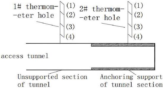
Figure 1 Schematic diagram of temperature monitoring in the test tunnel.
During the monitoring of the axial force of the bolt, the spraying layer of the test hole was supported by ordinary shotcrete and steel mesh. The steel mesh adopted 8 steel bars, and the mesh size was 200 200 mm. The steel mesh was close to the initial spray surface and welded to the end of the bolt to ensure that the steel mesh did not shake when concrete was sprayed. The primary support was made of C30 concrete with an impermeability grade of W8, and the thickness of the spray layer was 150 mm. In the spraying process, the means of primary spraying and secondary spraying were used. The primary spraying thickness was about 50 mm, and the secondary spraying was carried out after the bolts and hanging nets were installed. The GML-type bolt dynamometers were installed at 0.5 m, 1.0 m, and 1.5 m of the bolts on the left side and the vault to obtain the axial force data of the bolts.
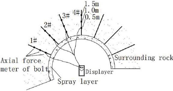
Figure 2 Schematic diagram of a bolt stress gauge.
2.3 Analysis of Monitoring Results
2.3.1 Temperature distribution pattern
Figure 3 shows the temperature variation of surrounding rocks during the construction. The tunnel rock mass was in a state of thermal equilibrium before excavation, and the temperature of each point in the rock mass remained unchanged. With the excavation of the tunnel, the ventilation and other cooling measures were applied to ensure the subsequent operations. There was convective heat transfer between the surrounding rocks and the air, and the temperature of the unsupported section and the anchoring support section gradually decreased.
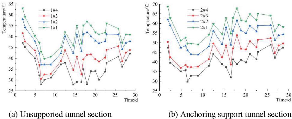
Figure 3 Temperature variation of surrounding rocks during construction.
At the beginning of the temperature measurement, the unsupported section was closer to the entrance, and the maximum temperature of the 1# measuring point was 62.8C, which was lower than the maximum temperature of the 2# measuring point (69C). After the sprayed layer was applied, the direct convective heat exchange between the surrounding rocks and the air was replaced by the heat transfer between the surrounding rocks and the sprayed layer, and the sprayed layer convectively exchanged heat with the air. Therefore, after the 2nd day, the temperature of the unsupported section continued to decrease, the lowest temperature of the 4# measuring point was 27C, and the temperature of the sprayed section began to stabilize. In the initial stage of support, in order to prevent cracks from evaporating too fast on the surface of the sprayed layer, the ventilation of the tunnel was suspended. The heat released by the cavity wall was less than the heat transferred by the deep rock mass, and the temperature of both increased to a certain extent. After the sprayed layer was completed, the ventilation was started again to prevent the temperature inside the spray layer from rising too fast, and the temperature continued to decrease slowly. The temperature trend was basically the same at different distances from the cavity wall in the same measuring hole, and the farther away from the cavity wall, the higher the temperature of the surrounding rocks.
2.3.2 Axial force distribution law of the bolt
Figure 4 shows the axial force of the bolt over time. From the figure, the axial force is tensile stress, and as time goes by, the slope of the curve gradually decreases, indicating that the increasing rate of the axial force of each bolt gradually decreases. The maximum axial force of the 1# bolt was at the front end of the bolt (close to the end of the cavity wall), and the maximum axial force was 19.8 kN. The maximum axial force of the 2# bolt was in the middle of the bolt, and the maximum axial force was 17.3 kN. After the 8th day, the axial force at the front end of the bolt hardly increased, indicating that the deformation of surrounding rocks was completed. The overall axial forces of the 3# and 4# bolts were relatively similar, the maximum axial forces of them were 13.7 kN and 12.8 kN, respectively, and the axial force at the front end of the bolt was much smaller than the overall axial force.
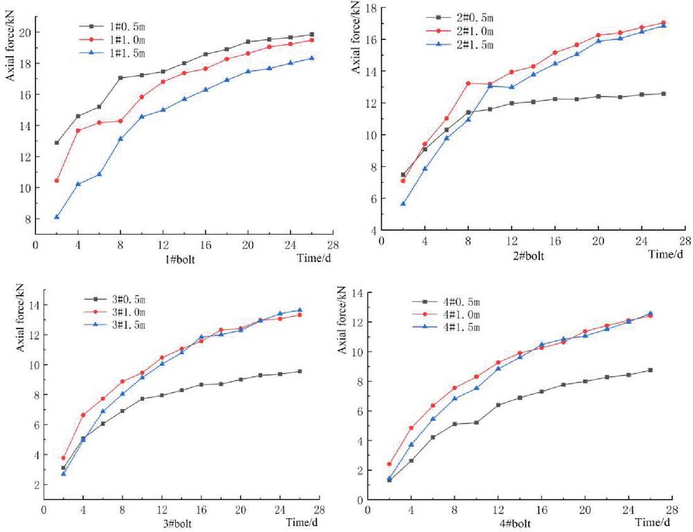
Figure 4 Variation of the measured axial force of the bolts over time.
3 Coupling Analysis of Characteristics of Plastic Zone in Hydraulic Tunnels with High Ground Temperature
3.1 Establishment of Finite Element Model of a Hydraulic Tunnel with High Ground Temperature
The length of tunnel excavation was much larger than the width of the section, therefore, it belongs to a kind of plane strain problem. As the tunnel face got farther away from the excavation site, the impact of excavation on the surrounding rock masses gradually decreased until it disappeared [12, 13]. According to the preliminary calculation, the error between 4 times the hole diameter and 20 times the hole diameter was less than 3%. In addition, the calculation range of surrounding rocks was selected as follows: 4 times the hole diameter on the upper, lower, left, and right sides were employed, the finite element software and the Drucker-Prager constitutive model were used to mesh the model, the element of thermal analysis was plane55, the element of plane entity was plane42, see Figure 5.
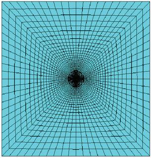
Figure 5 Finite element model.
Since the buried depth was 250 m, the boundary selected by the model was still far away from the ground, and the boundary temperature was not affected by changes in the surface temperature. Therefore, the boundary temperature function was a constant. The original temperature of the surrounding rocks was the initial temperature of the unexcavated rock mass, which was 80C, close to the actual measured temperature. According to the actual situation of the project, the tunnel was ventilated after excavation, and the boundary of the model cavity wall was the convective heat transfer boundary. On-site monitoring data showed that, the ventilation air temperature was about 20C, the convective heat transfer coefficient between a surrounding rock and air was 30 W(mC), and the convective heat transfer coefficient between sprayed layer and the air was 45 W(mC). The mutual coupling of temperature field and stress field is that the temperature change will affect the thermodynamic properties of surrounding rocks, and meanwhile to produce temperature stress acting on the surrounding rock. Therefore, the temperature-stress coupled simulation using numerical software was divided into direct coupling and indirect coupling, and the two coupling methods had little effect on the results [14]. In this paper, the indirect coupling was adopted, and the modeling process can be described as follows: (1) simulate the transient temperature field to obtain the temperature distribution at each time step; (2) calculate the initial ground stress of the model; (3) apply the transient temperature field result as a load on the model, and simulate the tunnel excavation and support process using the birth-death element method [15–17].
Assuming that the surrounding rock of the engineering section is the homogeneous rock mass, the thermal conductivity of surrounding rocks at different temperatures is selected according to the literature [18] and measured data, as shown in Table 1. From the measured data, the density of surrounding rocks is 2650 kg/m, the Poisson’s ratio is 0.28, the tensile strength is 1.4 MPa, the compressive strength is 40.85 MPa, the internal friction angle is 37, and the cohesion strength is 1.1 MPa.
Table 1 Thermodynamic parameters of surrounding rocks at different temperatures
| Temperature/C | Heat Conductivity Coefficient W(mC) | Coefficient of Linear Expansion 10C | Specific Heat J(kgC) | Elasticity Modulus GPa |
| 20 | 15 | 5 | 1060 | 7.1 |
| 30 | 14.37 | 5.4 | 1090 | 7.0 |
| 40 | 13.79 | 5.8 | 1120 | 7.0 |
| 50 | 13.25 | 6.2 | 1150 | 6.9 |
| 60 | 12.75 | 6.7 | 1180 | 6.9 |
| 70 | 12.29 | 7.2 | 1210 | 6.8 |
| 80 | 11.87 | 7.6 | 1240 | 6.7 |
3.2 Analysis of Characteristics of Plastic Zone
By numerically simulating the tunnel excavation without subsequent supports, the distribution and change law of the plastic zone of surrounding rocks after excavation were obtained. After excavation, the stress gradually released, and the plastic zone first appeared at the hance. Over time, the plastic zone gradually expanded from the hance to the spandrel and the depth of surrounding rocks. Ten days after excavation, the plastic strain value was 0.0011, the thickness of the plastic zone was about 0.43 m, which increased by 45% compared to the thickness on the 1st day after excavation. The upward and downward expansion was more obvious than the lateral expansion. The plastic zone around the tunnel exhibits a butterfly shape. This result is consistent with the conclusion in the literature [19] that, under high stress, the plastic spots first appeared in the surrounding rocks on the surface of the tunnel, then expanded into plastic regions, the regions of different parts were connected to form plastic rings, and eventually the plastic zone unevenly expanded.
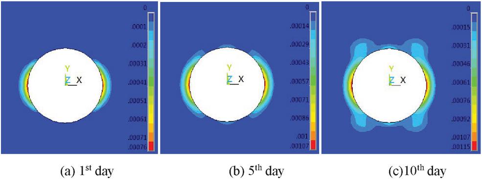
Figure 6 Plastic zone on days 1, 5, and 10 after excavation.
Fifteen days after excavation, more than 90% of the stress of surrounding rocks was released, and the range of plastic zone was unchanged. At this time, the plastic zone radius calculated by the theoretical formulas (1) and (2) under the DP criterion and the MC criterion was compared [20, 21], as shown in Table 2. From Table 2, the differences between the numerical simulation value and the calculation results by the two formulas are 1.52% and 2.54%, respectively. Therefore, the theoretical calculation results and numerical simulation results were within the error range.
| (1) |
where , ; is the radius of the plastic zone calculated by the DP criterion; a is the tunnel radius; is the original rock stress; is the supporting resistance, and k and are the DP criterion material constants.
| (2) |
where is the radius of the plastic zone calculated by the MC criterion; c is the cohesive force, and is the angle of internal friction.
Table 2 Radius of plastic zone by three calculations
| DP Criterion | MC Criterion | Numerical | |
| Computes Values | Computes Values | Simulation Value | |
| Radius of plastic zone(m) | 2.00 | 1.92 | 1.97 |
In summary, as time went by, the plastic zone of surrounding rocks expanded upwards and downwards, the thickness of the plastic zone increased, and the plastic strain gradually increased. The plastic zone at the hance and spandrel was mainly caused by compressive stress. The surrounding rocks with poor lithology was prone to fracturing. The plastic zone at the vault was mainly caused by tensile stress, which was easy to cause tensile cracks and collapse. Therefore, after the tunnel is excavated, initial support is required to enhance the stability of surrounding rocks.
In the simulation, the initial boundary temperature was set to 60C and 100C, and the distribution of plastic zone 10 days after excavation is shown in Figure 9.
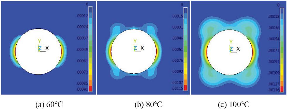
Figure 7 Plastic zone at 10 days after excavation at 60C, 80C and 100C.
At different initial temperatures, the range of the plastic zone and the maximum deformation of surrounding rocks at 10 days after excavation both increased with the increase in temperature. At 60C, the maximum deformation of the plastic zone was 0.00091, and the thickness of the plastic zone was 0.34 m. At this time, the plastic zone was distributed at the hance on both sides. When the initial temperature was 80C, the maximum deformation and thickness of the plastic zone increased by 26% and 8%, respectively compared with those at 60C, and the plastic zone mainly expanded toward the spandrel and vault. When the initial temperature was 100C, the maximum deformation of the plastic zone was 0.00136. At this time, there was an obvious malignant extension of the plastic zone to the depth at the spandrel, and the thickness of the plastic zone reached 1.3 m. The simulation results showed that, the higher the initial temperature of surrounding rocks, the greater the temperature difference between the cavity wall and the inner surrounding rocks after excavation, and the greater the influence of its temperature stress on the plastic zone of surrounding rocks. The higher the temperature of surrounding rocks, the more likely the plastic zone will deteriorate and develop toward the depths of surrounding rocks at the spandrel. Therefore, after tunnel excavation in a high ground temperature environment, the strength and form of the supporting structure need to be adjusted. The higher the temperature, the more attention should be paid to the spandrel and vault.
4 Analysis of Anchoring Properties in Hydraulic Tunnels with High Ground Temperature
4.1 Analysis of Mechanical Properties of the Bolts
The fully grouted bolt prevents the deformation of surrounding rocks through the bonding or friction force between the bolt body and the bonding material. After the bolts are applied in underground works, part of the surrounding rock body near the cavern space moves in the direction of the interior of the excavated tunnel, and the bolts prevent the surrounding rocks from moving, at which time the surface of the bolts is subjected to the shear force pointing to the tunnel. In the deep surrounding rocks far away from the cavern, the anchor body has a greater displacement than the surrounding rock mass, and the shear stress between them points away from the tunnel. Because the direction of the shear stress on the two ends of the bolt is opposite, there must be a zero point of shear stress on the bolt body. TJ Freeman [22] and Wang Mingshu [23] etc. called this point the “neutral point”. At the neutral point, the shear stress is 0, and the axial force reaches the maximum. Therefore, the approximate position of the neutral point can be determined by the point of maximum axial force in the simulation results.
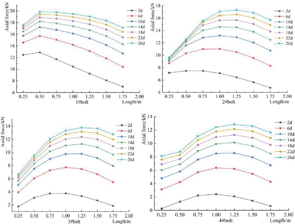
Figure 8 Variation of axial force of different bolts over time.
The axial force of the bolt first increased and then decreased along the bolt body pointing to the depth of surrounding rocks. Generally, the axial force in the middle of the bolt body was greater than the axial force at both ends. According to the curve, after anchoring support for 2 days, the maximum axial force of the 1# bolt is at 0.5 m, the maximum axial force of the 2# and 3# bolts is at 0.8 m, and the maximum axial force of the 4# bolt is at 1.0 m. Therefore, the neutral points of the bolts at different positions are different. The neutral point of the bolt closer to the vault is farther away from the cavity wall, and vice versa. After anchoring support, the maximum axial force of the 2#, 3#, and 4# bolts all moved away from the cavity wall, and the position of the neutral point moved from close to the cavity wall to away from the cavity wall. The axial force at each point of the bolts increased with time, which was consistent with the fact that after the anchoring support was applied, the stress of surrounding rocks would still be released over time. The displacement and plastic zone continued to increase, the bolt restricted the growth of the displacement of surrounding rocks, the shear force between them gradually increased, and the axial force at each point of the bolt body gradually increased. The axial force growth of the 2# bolt at the spandrel near the tunnel almost stagnated after 8 days of anchoring support. According to the simulation results, the plastic zone at this point was expanding unevenly. After the spandrel near the cavity wall was anchored, the deformation of the plastic zone no longer increased and then developed deeper after the stress of part surrounding rocks was released. Therefore, the growth of axial force of the bolt body only within the spandrel plastic zone was stagnant, and the stress of the rest of the bolt body increased normally.
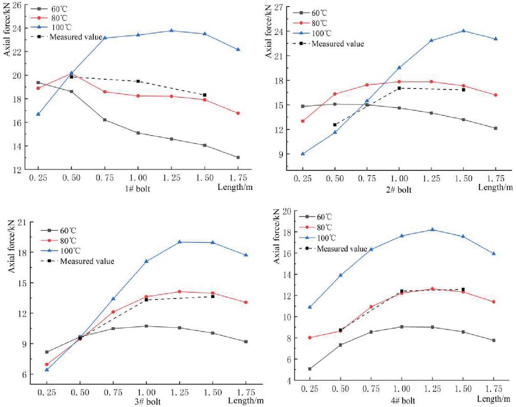
Figure 9 Axial force of the bolt at different temperatures after 15 days of anchoring support.
The axial force of the bolt at 10 days after anchoring support at different initial surrounding rock temperatures is shown in Figure 9. The measured axial force of the bolt is generally close to the simulated value at the same temperature. The differences between the measured value and the simulated value at a distance of 1 m from the cavity wall of the 1# anchor and 0.5 m from the cavity wall of the 2# anchor are large, but both values are within 10%, indicating that the simulation results can be referenced. The reason for the difference in data may be that the stress state of the initial support of the high ground temperature tunnel under the action of surrounding rock load and temperature stress is more complicated, and there are differences in topographic and geological conditions between the isotropic homogeneous body used in the numerical simulation section and the field test section [24, 25]. The axial force of the 1#, 2#, and 3# bolts near the cavity wall was inversely related to the initial surrounding rock temperature. The lower the temperature, the greater the axial force. The axial force of the bolts far away from the cavity wall was positively correlated with the temperature. The higher the temperature, the greater the axial force changes along with the bolt. This result indicated that the higher the temperature, the greater the effect of temperature stress on the bolt due to temperature changes. At the same position (vault) of the 4# bolt, the higher the initial surrounding rock temperature, the greater the axial force. The axial force of the bolt increased almost proportionally with the increase in temperature. The ratio of the axial force of the bolt at the initial temperatures of 60C to 80C was less than the ratio at 80C to 100C. This result indicated that the higher the initial temperature of surrounding rocks, the more obvious the temperature effect under the same temperature difference, and the greater the effect of temperature stress on the bolt. The higher the temperature of the bolt at the same position, the greater the maximum axial force value of the bolt, and the farther away from the cavity wall, that is, the farther the neutral point was from the tunnel wall. In actual engineering anchoring, the size and strength of the bolt can be adjusted according to the temperature.
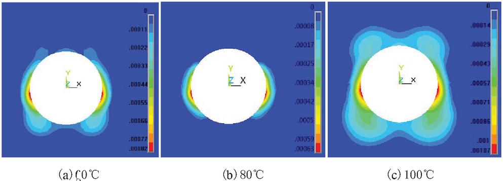
Figure 10 Plastic zone after 10 days of support at 60C, 80C and 100C.
4.2 Distribution of Plastic Zone in Surrounding Rocks After Anchoring
Figure 10 shows the plastic zone of surrounding rocks under different initial temperature environments after 10 days of anchoring support. The plastic zone of the anchored part has obvious changes compared with the unanchored plastic zone of the same period. After 10 days of anchoring support, the maximum plastic strain values at 60C, 80C, and 100C are 0.00063, 0.00082, 0.00107, which is smaller than those of the unanchored section by 30.7%, 28.7%, and 21.3%, respectively. At these three temperatures, the range of the plastic zone decreased by 9%, 20%, and 24%, respectively. The plastic deformation rate of surrounding rocks decreased after supporting. Bolt-shotcrete support can limit the development of plastic zone in the high-temperature surrounding rocks. The higher the temperature, the more obvious the support effect. Therefore, in actual engineering, after the excavation in the high ground temperature tunnel, timely and reasonable support should be carried out to limit the development of the plastic zone.
5 Conclusion
For the problems of plastic zone changes before and after the initial support and the evolution of axial force of the bolt during the construction of high ground temperature hydraulic tunnels, the following conclusions were obtained through comparison and demonstration of actual measurement analysis and numerical simulation:
(1) After the excavation of the high ground temperature hydraulic tunnel, the plastic zone first appeared in the hance in a crescent shape, and then expanded to the spandrel and vault to form a ring or butterfly shape. The higher the initial temperature of surrounding rocks, the larger the plastic deformation and the range of the plastic zone. When the temperature exceeded 80C, more plastic zone expanded to the spandrel and vault.
(2) At the same time, the closer the anchor was to the vault, the farther its neutral point was from the cavity wall. As the stress was released, the neutral point moved from close to the cavity wall to away from the cavity wall. At the same position, the higher the temperature, the greater the effect of temperature stress, and the farther away the neutral point was from the cavity wall.
(3) Anchoring support can effectively limit the development of plastic zone in surrounding rocks under high ground temperature. For tunnels with initial temperatures of 60C, 80C, and 100C, after 10 days of anchoring support, the range of the plastic zone was reduced by 9%, 20%, and 24%, respectively, and the maximum axial force of the bolts was 19.4 kN, 20.1 kN, and 23.8 kN, respectively. The higher the temperature under similar working conditions, the higher the strength of the bolt required.
Acknowledgments
This research was supported by the National Natural Science Foundation of China (Grant No. 51769031), Regional innovation Guidance Plan project of the XPCC (Grant No. 2021BB004).
Conflict of Interest
We all declare that we have no conflict of interest in this paper.
References
[1] Wang Mingnian, Hu Yunpeng, Tong Jianjun, et al. Experimental study on shear mechanical properties and thermal damage model of shotcrete-rock interfaces under variable high temperatures[J]. Chinese Journal of Rock Mechanics and Engineering, 2019, Vol. 38(1): 63–75.
[2] Wang Mingnian, Hu Yunpeng, Liu Dagang, et al. A Study on the Heat Transfer of Surrounding Rock-Supporting Structures in High-Geothermal Tunnels[J]. Applied Sciences, 2020, Vol. 10(2307): 2307.
[3] Wu Di, Deng Tengfe, Zhao Runkang, et al. THM modeling of ground subsidence induced by excavation of subway tunnel.[J]. Computers & Geotechnics, 2018, Vol. 94: 1–11.
[4] Su Guoshao, Qin Zihua, Peng Lifeng, et al. Load-bearing characteristics of surrounding rock of hydraulic tunnels under high temperature and hydraulic pressure conditions using coupled thermo-hydro-mechanical-damage numerical model[J]. Rock and Soil Mechanics, 2018, Vol. 39(1): 308–319,330.
[5] Hu Yunpeng, Wang Qiling, Wang Mingnian, et al. A study on the thermo-mechanical properties of shotcrete structure in a tunnel, excavated in granite at nearly 90C temperature[J]. Tunnelling and Underground Space Technology, 2021, Vol. 110: 103830.
[6] Li Fuhai, Jia Yi, Hu Dinghan, et al. Experimental Study on Ultimate Pullout Force of Anchor Rods under Working Load and High Ground Temperature Environment[J]. Journal of the China Railway Society, 2018, Vol. 40(2): 125–131.
[7] Li Fuhai, Jin Hesong, Hu Dinghan, et al. Influence of temperature and roughness of surrounding rocks on mechanical behavior of rock bolts.[J]. Soil Dynamics & Earthquake Engineering, 2017, Vol. 103: 55–63.
[8] Yao Xianchun, Li Ning, Wan Kecheng, et al. Experimental and Analytical Study on Mechanical Properties of High Rock Temperature Diversion Tunnel.[J]. Advances in Civil Engineering, 2019, Vol. 2019: 1–11.
[9] Fan Lei. Study on the Key Techniques for Comprehensive Control of Heat Harm of the Deep-buried and Super-long Tunnel with High Ground Temperature[J]. Modern Tunnelling Technology, 2019, Vol. 56(6): 1–10.
[10] Li Ming, Mao Xianbiao, Yu Yuanlin, et al. Stress and deformation analysis on deep surrounding rock at different time stages and its application[J]. International Journal of Mining Science and Technology, 2012, Vol. 22(3): 301–306.
[11] Yu Weijian, Wang Weijun, Chen Xinyuan, et al. Field investigations of high stress soft surrounding rocks and deformation control[J]. Journal of Rock Mechanics and Geotechnical Engineering, 2015, 7(04): 421–433.
[12] Sahoo, J.P., Kumar, J. Required Lining Pressure for the Stability of Twin Circular Tunnels in Soils[J]. International Journal of Geomechanics, 2018, Vol. 18(7): 04018069.
[13] Puja Dutta, Paramita Bhattacharya. Determination of support pressure for semi-elliptical tunnels in anisotropic and nonhomogeneous soil by lower bound limit analysis[J]. Sâdhanâ,2021, Vol. 46(1).
[14] Hou Xiongbin, Jiang Haibo, Mo Zuguo. Analysis on thermo-stress coupling of surrounding rock for water diversion tunnel under high ground temperature[J]. Water Resources and Hydropower Engineering, 2017, 48(07): 43–48.
[15] Claudio Oggeri, Pierpaolo Oreste, Giovanni Spagnoli. The influence of the two-component grout on the behaviour of a segmental lining in tunnelling[J]. Tunnelling and Underground Space Technology, 2021, Vol. 109: 103750.
[16] Alberto Meda, Zila Rinaldi, Simone Spagnuolo, Colin M. Eddie. Behaviour of FRC segments with GFRP cage under TBM thrust in presence of GAPs[J]. Tunnelling and Underground Space Technology, 2021, Vol. 107: 103669.
[17] Stefania Fabozzi, Salvatore Antonio Biancardo, Rosa Veropalumbo, Emilio Bilotta. I-BIM based approach for geotechnical and numerical modelling of a conventional tunnel excavation[J]. Tunnelling and Underground Space Technology, 2021, Vol. 108: 103723.
[18] Mo Zuguo, Jiang Haibo, Hou Xiongbin. Study on Transient Temperature and Stress Coupling of Surrounding Rock of Water Diversion Tunnel with High Ground Temperature under Different Excavation Methods[J]. Water Power, 2019, 45(02): 58–63.
[19] Wang Weijun, Guo Gangye, Zhu Yongjian, et al. Malignant development process of plastic zone and control technology of high stress and soft rock roadway[J]. Journal Of China Coal Society, 2015, 40(12): 2747–2754.
[20] Zhai Suoye, He Xianguo. Solution of D-P criterion of plastic district of surrounding rock of roadway[J]. Chinese Journal of Underground Space and Engineering, 2005(02): 223–226.
[21] Chen Peng, Xu Bohou. Matching method of D-P yield criterions to M-C based on value of internal frictional angle[J]. Chinese Quarterly of Mechanics, 2012, 33(02): 269–274.
[22] Freeman T.J. The behavior of fully-bonded rock bolts in the Kielder experimental tunnel[J]. Tunnels and Tunneling Journal, 1978, (10): 37–40.
[23] Wang Mingsu, He Xiuren, Zhang Yutian. Mechanical model of full-length anchored bolt and its application[J]. Metal Mine, 1983, (4): 24–29.
[24] Witold Pytel, Piotr Mertuszka, Krzysztof Fuławka, et al. Resultant axial stresses in instrumented rockbolts induced by dynamic effects occurred due to multi-face blasting in the working areas[J]. Tunnelling and Underground Space Technology, 2021, Vol. 116: 104088.
[25] Reza Masoudi, Mostafa Sharifzadeh, Masoud Ghorbani. Partially decoupling and collar bonding of the encapsulated rebar rockbolts to improve their performance in seismic prone deep underground excavations.[J]. International Journal of Mining Science and Technology, 2019, Vol. 29(3): 409–418.
Biographies

Yuhang Huang graduated from Xichang University with a bachelor’s degree in Water Conservancy and Hydropower Engineering in June 2019. Currently, as a postgraduate student in the School of Hydraulic Engineering and Architecture, Shihezi University. Research direction is hydraulic structure engineering, and the main research content is anchoring mechanism of hydraulic tunnel at high ground temperature.

Haibo Jiang is a Ph.D. student at the Xinjiang Agricultural University in China since spring 2008, received doctorate degree in water conservancy and hydroelectric engineering in 2011. Scientific research is mainly carried out on the prevention and control of freezing damage of hydraulic materials and water engineering in cold areas, hydraulic structure performance, stress and deformation of rock and soil mass and disasters, etc., with obvious characteristics in multi-field coupling effect of hydraulic structure, freeze-thaw damage and damage mechanism of rock and soil mass, as well as the coupling mechanism of frost resistance, heat insulation and mechanics of hydraulic materials.
European Journal of Computational Mechanics, Vol. 30_4–6, 481–500.
doi: 10.13052/ejcm2642-2085.30468
© 2022 River Publishers