Structural Dynamics of Bridges Under the Coupling Effect of Windmills and Bridges
Guoqing Huang1, Na Ren2 and Hengbin Zheng3,*
1Guangdong Provincial Institute of Transportation Planning and Design Group Co., Ltd., 510507, China
2Guangdong Heli civil Engineering Co., 511400, China
3College of Water Conservancy and Civil Engineering, South China Agricultural University, Guangzhou, Guangdong, 510642, China
E-mail: zhhb@scau.edu.cn
Corresponding Author
Received 24 February 2023; Accepted 26 March 2023; Publication 29 April 2023
Abstract
To analyze the coupled dynamics effects of existing railroad frame bridge structures under the action of traffic, a coupled train-ballast track-suspension bridge girder-soil dynamics model is established based on railroad large system dynamics and finite element theory. The joint ABAQUS-MATLAB simulation, time-varying coupling, and multi-step dynamic iterative solution strategies are introduced to numerically simulate the mechanical properties of existing railroad structures under the coupled effects of wind loads and traffic action. Specifically, (1) a dichotomous method is proposed to investigate the static behavior of the bridge in the bridge-forming state, and the maximum upper arch of the stiffened girder is 3.67 cm, which occurs at about 1/4 and 3/4 positions of the main span, and the lower deflection of the side span is larger, and the maximum lower deflection occurs at 11.04 cm in the span of the 110 m side span. The vertical acceleration in the span increases immediately with the maximum peak of 30 cm/s, while the lateral acceleration is maintained within 20 cm/s. (2) The effects of the stiffness of the rail fasteners and the bridge plate support stiffness on the dynamics were studied. (3) The results of the time-domain analysis are in general agreement with the simulation data, except for the error of the ambient vibration background existing at the peak. The correctness of the simulation model is verified.
Keywords: Bridge dynamic response, wind-vehicle-bridge coupling, optimization of mechanical parameters, multi-step iterative method, vibration test.
1 Introduction
With the development of the railroad transportation business, railroad bridges are also developing towards large spans [1]. In the actual project, the railroad line will inevitably need to cross large valleys and river zones, putting forward high requirements for the span of railroad bridges. Among them, suspension bridges are strong enough to meet the demand of large spans with their powerful spanning ability. Many railroad suspension bridge projects are about to be put into practice, but the low stiffness of suspension bridges themselves, the prominent geometric nonlinear characteristics, and the high influence of wind loads threaten the safety of train traffic and bridge structure. In view of this, it is necessary to study the traffic safety on railroad suspension bridges subjected to unfavorable wind loads and to investigate the coupling effect and analysis method of wind-vehicle-bridge of railroad suspension bridges.
At present, many scholars at home and abroad have conducted in-depth research for the determination of reasonable bridge formation state of ground suspension bridges, and many important results have been achieved at the same time. Tang Mao-Lin [2, 3] derived the basic equation of the segmental suspension line theoretical cable section and proposed to use the method of continuous fractional solution for the problem that the unstressed length cannot be derived from the explicit expression in the basic equation of the cable section. Xiao Rucheng [4] considered that when the second-phase constant load was shared by the main cable and stiffened beam, the bridge-forming sling force was obtained, and then the bridge-forming main cable line was calculated according to the bridge-forming sling force. Li Chuanxi and Ke Hongjun [5] proposed the “progressive model method” for complex self-anchored suspension bridges, and used Fortran language to compile the main cable shape-finding program Sus_Cal, which is of practical significance for the mechanical analysis of the bridge state of suspension bridges. The method of Yongren Pan [6] is to gradually approach the target state by repeated forward analysis, to obtain the numerical analysis results of the dynamic mode of the bridge. Li Yongle [7–10] used the spectral solution method to simulate the pulsating wind field of the bridge tower and the main girder separately for the strong vibration coupling correlation between the main girder and the bridge tower of a large-span cable-stayed bridge structure, and calculated the wind speed time segments at each measurement point. Pan Yonren et al. [11] used the numerical integration method to obtain fine calculations of the geometry and internal forces of the constant load structure of suspension bridges. LI, as well as Peng’s team [12–18], conducted a large number of experimental tests on large-span suspension bridges such as complex mountain canyons and deep-cut canyon bridges, thus providing important references for the development of codes such as specified wind loads. Xu Hongtao, Wang Kai, Liao Haili, Ma Cunming, et al. [19–22] improved the inverse distance weighted wind speed interpolation method for bridges in mountainous canyon areas and explored the influence law of wind loads. Zhang Zhitian et al. [23, 24] obtained the power spectral density functions of train dynamic action and wind field based on a statistical analysis of the data with the engineering background of Shorzhai Bridge in western Hunan Province. Wang and Cox [25, 26] carried out a series of experiments on top of a steel bridge to investigate the range of the main frequency distribution of noise during train passage. NGAI et al. [27–33] used a boundary element acoustic model for the viaduct The relevant calculations were performed and the spectral characteristics of the bridge structure noise were analyzed. Li Q et al. [34] also used the boundary element method to calculate the structural noise of concrete U-shaped girder bridges, and after comparing the predicted results with the analysis of field test data, it was confirmed that the accuracy of the adopted noise calculation model was high. Shaoqin Wang et al. [35] established a wind-train-bridge coupled system with the self-programmed software NWVB. For the context of a suspension bridge on Wufeng Mountain, and analyzed the influence of geometric nonlinear factors on the bridge acceleration time profile considering the suspension bridge. The team of Dejun Liu and Xiaozhen Li [36] considered the effects of track structural reference vibration, the fluid-solid coupling effect between wind and bridge, the solid contact effect between the car and rail, and the spatial pulsation effect of wind on the car. The bridge dynamic analysis software WTTBDAS was developed and applied to several practical projects. Xinyu Xu [37] established a refined coupled wind-vehicle-bridge system vibration model based on the rigid-flexible coupling method and measured the static three-part force coefficients of trains in different terrains through wind tunnel tests. The above studies have played an important role, but the efficient and refined model of the vehicle-bridge coupled system has not been realized, and the dynamic effects of suspension bridges under train loads as well as wind loads have not been explored.
The joint simulation strategy and multi-step iterative solution help the secondary development of the model. The fast convergence of the computational results is also ensured. Therefore, in this paper, a refined model combining MATLAB secondary development and finite element is established for the railroad suspension bridge engineering example. The improved model established in this paper, in addition to the refinement of the mesh model. Due to the import of the external control interface program, functions and data can be imported according to the needs of the research content, thus improving the computational efficiency and accuracy. The inherent mechanical properties of the suspension bridge are explored. A parametric analysis of the structure is also carried out, and the structural performance under the wind-vehicle-bridge coupling and the effect of the dynamics are investigated. The research process was carried out in five steps, as shown in Figure 1.
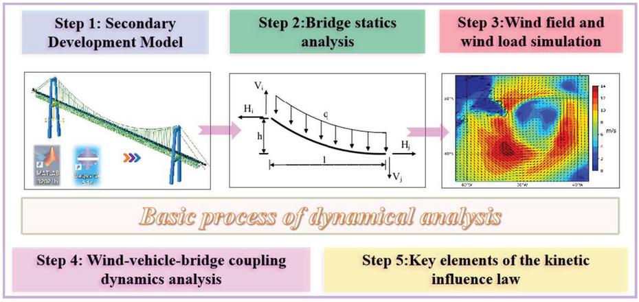
Figure 1 Typical Data Center Infrastructure [18, 19].
2 Static Analysis in Bridge Formation Conditions Center Infrastructure and Power Consumption
Based on the segmental suspension chain line main cable finding theory of suspension bridges, the static calculation considering geometric nonlinearity is carried out, and the correctness of the static model is verified by the displacement results under the constant load of the bridge formation state. The static results can be used as the initial state of the bridge in the coupled vehicle-bridge dynamics analysis.
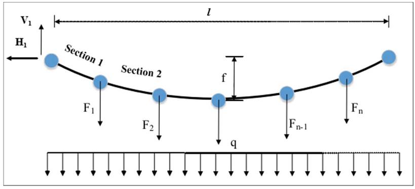
Figure 2 Flow of wind-vehicle-bridge coupling characteristics analysis in this study.
2.1 Calculation Method for Finding the Shape of the Main Cable of the Suspension Bridge
Since the force on the cable section should be balanced, the horizontal force on the j end of the cable section is equal to the horizontal force on the I end of the cable section, and the vertical force on the I end of the cable section is numerically different from the vertical force on the j end of the cable section by one self-weight of the cable section, i.e. qS0. According to the horizontal force and vertical force on the j end of the 1st cable section, the horizontal force and vertical force on the I end of the 2nd cable section can be obtained by superimposing the vertical boom force of the boom, see Figure 2. The height difference and unstressed length of the No. 2 cable section can be obtained, and so on, to obtain the height difference and unstressed length of all cable sections. The core idea of the derivation process of the conventional parabolic method to calculate the stress-free length of a bridge is as follows. Assume that the bridge is in the form of a suspended chain line, i.e., the bridge has equal heights at both end points and a continuous curve in the middle part.
| (1) | |
| (2) | |
| (3) |
Where: l – the span value of the cable section. Where: l-value of the span of cable section. H, H-horizontal force at the end i and j of cable section, where H is not reflected in the formula; V, V-vertical force at the end i and j of cable section1, where V is not reflected in the formula. q-self-weight set of cable section; S-unstressed length of the cable section.
The above equation reflects the relationship between the single cable span value l, the height difference value h, the length of stress-free S0, which are the three-distance dimensional quantities, and the horizontal force Hi, vertical force Vi, which are the two force dimensional quantities at one end of the cable section, for the Equation (1) such a system of equations, theoretically only need to know any three of the above five variables can be solved for the remaining two variables, thus laying the foundation for the suspension bridge main cable shape-finding This laid the foundation for the calculation of the suspension bridge main cable finding.
| (4) | |
| (5) |
Where, l – main span horizontal span of the main cable; f – main span drape of the main cable; q – self-weight set of the cable section; Sim – inaccurate stress-free length of the main span of the main cable obtained according to the conventional parabolic method [38, 39].
2.2 Static Analysis Results
ABAQUS Standard static analysis step is added to the aforementioned interactions, loads, and boundary conditions. The joint self-programming and the geometric nonlinearity of the structure are considered. When the train is not yet on the bridge, the suspension bridge is in static equilibrium subject to constant load only, then the train drives to the bridge and the mutual coupling between the train and the bridge occurs, so the static equilibrium state of the suspension bridge into the bridge subject to constant load only is the basis for the study of the vehicle-bridge coupling effect, and it is necessary to ensure the accuracy of the static analysis results before conducting the vehicle-bridge coupling analysis.
The displacement of the suspension bridge is only under constant load, as shown in Figure 3. It can be obtained that the maximum up-arch of stiffened girder is 3.67 cm under constant load, which appears at about 1/4 and 3/4 position of the main span, and the down-deflection of the side span is larger, the maximum down-deflection appears in 110 m side span, which reaches 11.04 cm; the down-deflection in 98 m side span is also larger, which reaches 7.59 cm; the displacement in the main span is not large; the deflection in 110 m side span is the largest, and the bending moment in this The bending moment of the cross-section is also larger, reaching 6.251 105 kN-m in total. The bending moment of the steel truss structure is 4.235 105 kN-m, the bending moment of the orthogonal anisotropic steel bridge panel is 1.877 105 kN-m, the compression force on the steel bridge panel is 1.410 104 kN, and the tension force on the steel truss structure as a whole is 2.890 104 kN. The pressure on the single upper chord is 10.01010 kN. The pressure is 10.010 103 kN, and the tension of a single lower chord is 2.455 10 kN. The above deformation are in line with the specification design requirements. In the actual project, it should be constantly monitored. If the actual project deformation value exceeds the specification range, appropriate measures need to be taken to repair or strengthen.
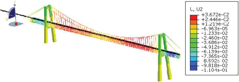
Figure 3 Static analysis results.
3 Bridge Wind Load and Wind Field Simulation
In this paper, the wind speed spectral density function is decomposed into random wind speed spectral time intervals by using the harmonic synthesis method to simulate a random wind field. In this study, a total of 53 wind simulation points are set on the main span of the suspension bridge, and the pulsating wind speed probability density function of the 53 simulation points, followed by triangular decomposition, is calculated by nested for loops to obtain the overall result of the pulsating wind speed time course. The results are shown in Figure 4. Among them, the harmonic approach to model wind load is based on the following derivation process: 1. The wind speed signal is decomposed into harmonic components of different frequencies, i.e., the wind speed signal is decomposed by Fourier transform or wavelet transform, etc. 2. For each harmonic component, the corresponding wind coefficient is calculated by establishing the correspondence between wind coefficient and wind speed. 3. Multiply the wind coefficient of each harmonic component by the corresponding harmonic amplitude to get the wind load of each harmonic component. 4. Superimpose the wind loads of all harmonic components to obtain the simulated wind load signal.
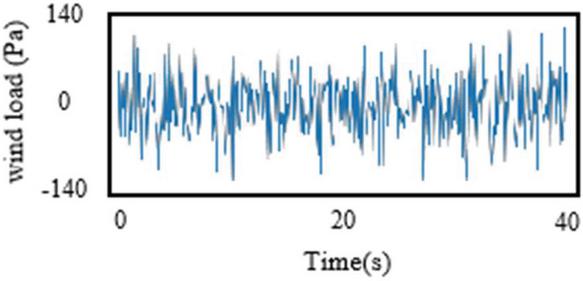
Figure 4 Basic flow chart of LSTM in this hydrological model.
In addition, before the wind load is loaded, it is necessary to set the positive and negative wind load values in both directions, specifically setting the wind load value acting vertically from the inside of the line as positive and the wind load value acting on the outside as negative. Therefore, for the natural wind load acting on the outside, it is necessary to take the negative value to load the way. For the pulsating wind load, which has alternating positive and negative wind pressure, it is chosen to be loaded vertically on the structure from the inside of the line in the form of a dynamic load.
4 Analysis of Wind-Vehicle-Bridge Coupling Effect
In this chapter, based on the theory of wind-vehicle-bridge coupling analysis, the calculation principles of wind loads on the train and wind loads on the bridge during the train passing over the suspension bridge are explored, and the wind loads on the train and wind loads on the bridge are imposed separately through MATLAB in conjunction with ABAQUS secondary development, and the method of wind-vehicle-bridge coupling analysis in ABAQUS is elaborated. The refined finite structure schematic of the secondary development is shown in Figure 5. The wind-car bridge coupled vibration analysis model was established based on the Jinshajiang Railway Suspension Bridge as the engineering background, and the test analysis was verified.
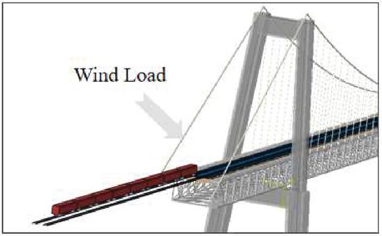
Figure 5 Wind-vehicle-bridge coupling model based on secondary development.
4.1 Wind-Vehicle-Bridge Coupling Dynamics Model
The training model mainly consists of the car body, bogie, and wheel pair, and the car body is connected with the bogie by two-series suspension spring damping, and the bogie is connected with the wheel pair by one-series suspension spring damping. In the axle system, the bridge structure should be simulated by the finite element method, and different units are used to simulate the different components of the bridge structure in terms of their component types and mechanical properties. Each unit in the system has its stiffness matrix and mass matrix and damping matrix, and the overall stiffness matrix, mass matrix, and damping matrix of the system are solved at the nodes by following the “right number” rule. The role of the track structure in the axle coupling system should not be ignored, and the influence of the track structure must be considered in the fine axle calculation and analysis. An example of the theoretical modal calculation of the axle coupling part is shown in Figure 6.
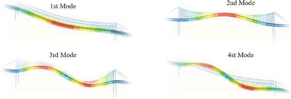
Figure 6 Schematic representation of the first four orders of modalities of the coupled part of the bridge.
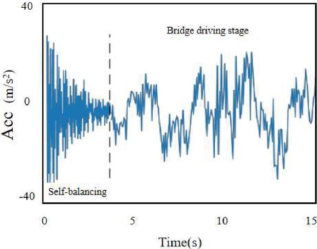
Figure 7 Axle coupled vertical dynamic acceleration.
4.2 Analysis of Kinetic Effects
The bridge structure will vibrate under the action of the train load, from the perspective of structural safety, the bridge structure should be. The results of the acceleration on the girders are shown in Figures 7 and 8 during the course of a train passing through the full bridge. During the self-equilibration phase of a bridge, the vibration response of the bridge structure decreases over time until it eventually plateaus. This process is easy to understand because during the self-equilibrium phase, the bridge is subjected to smaller loads and the initial vibration amplitude of the bridge structure is smaller, so the dynamic acceleration of the bridge is more likely to level off. However, when the bridge is subjected to larger loads, such as when a vehicle is traveling on the bridge, the vibration response of the bridge structure is affected by a number of factors, resulting in differences between the vertical and lateral waveforms.
It can be seen that at the end of the self-balancing stage, the dynamic acceleration of the bridge has stabilized, and when the train travels to the bridge, the acceleration of each position on the stiffener beam starts to change. The maximum peak is 30 cm/s, while the lateral acceleration remains within 20 cm/s. The vertical acceleration at the middle of the main span reaches its maximum at 26.7 cm/s, while the peak vertical acceleration at one-quarter and three-quarters of the main span is smaller than that at the middle of the span, and is controlled within 20 cm/s.
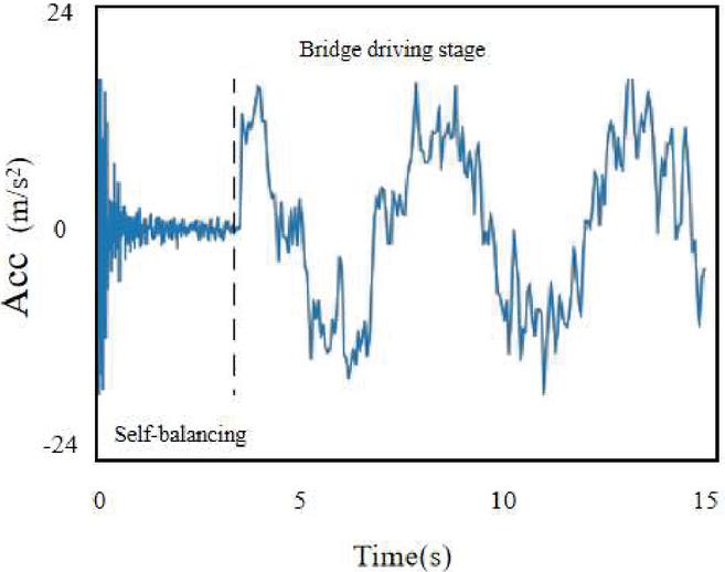
Figure 8 Axle coupled lateral dynamic acceleration.
4.3 Influence Law of Key Parameters
The dynamic performance of the structure is an inherent property, and the parameters of each member of the vehicle track bridge structure, which affects the dynamic effect, are therefore calculated separately for the dynamic response law of the bridge structure when the parameters such as fastener stiffness and bridge support stiffness are changed. Thus, the corresponding theoretical basis is provided for the future improvement and refinement of the track bridge structure.
As can be seen from Figure 9. This parameter range is mainly combined with the actual working conditions displayed. When the fastener stiffness increases from 10 kN/mm to 70 kN/mm, the maximum vibration acceleration of the track plate increases from 42.33 m/s to 56.13 m/s, which is 1.33 times larger and the change amplitude is larger. And the maximum vertical displacement decreases from 2.29 mm to 2.27 mm with a changing amplitude of 0.02 mm, which can ignore the vertical displacement change of the track plate. It can be seen that with the increase of fastener stiffness, the energy generated by the interaction between wheels and rails will be transferred to the track plate more, thus intensifying the vibration response of the track plate. The maximum vertical acceleration of the track plate increases by 10.12 m/s, 2.75 m/s, and 0.93 m/s, respectively, when the fastener stiffness increases from 10 kN/mm to 70 kN/mm, it can be found that the vibration response of the track plate changes dramatically when the fastener stiffness increases from 10 kN/mm to 30 kN/mm, and the vibration response of the track plate changes dramatically when it increases from 30 to 70 kN/mm. the change of vibration response of the plate shrinks.
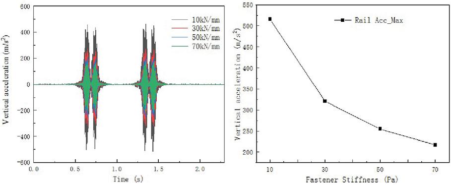
Figure 9 Effect of fastener stiffness on dynamic performance.
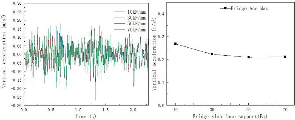
Figure 10 Effect of bridge plate stiffness.
For the same reason Figure 10 shows that when the bridge plate support stiffness increases from 10 kN/mm to 70 kN/mm, the maximum vertical vibration acceleration in the bridge span changes from 2.29 m/s to 2.27 m/s with a changing amplitude of 0.02 m/s. Therefore, it can be seen that the increase in bridge plate support stiffness leads to a slight decrease in the overall acceleration of the bridge body.
5 Experimental Test Comparison
To verify the correctness of the above model and results, the vibration acceleration of the beam is measured and compared, and analyzed with the previous test results. Considering the test’s difficulty, in this paper, only the simple measurement point suggested by the bridge is selected as the verification target, to verify whether the model is relevant to the actual. The calculated results are as follows.
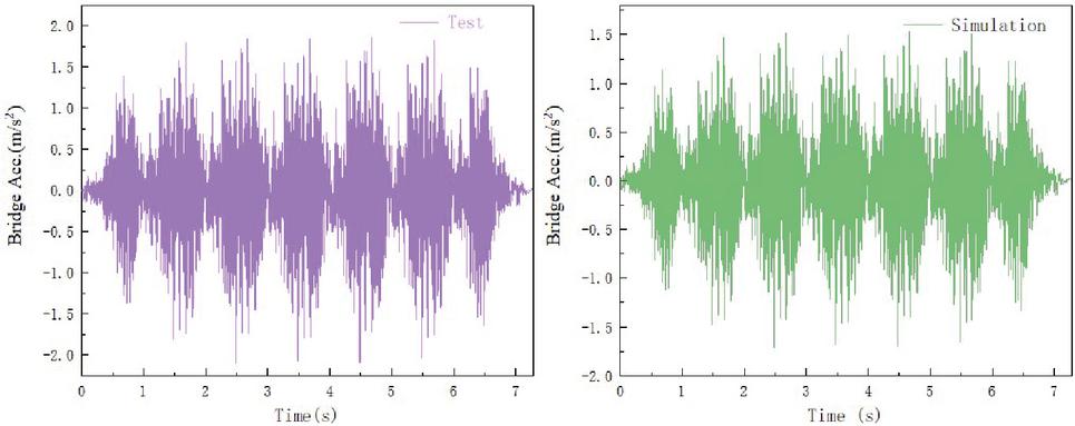
Figure 11 Effect of bridge plate stiffness.
As can be seen from Figure 11, there is a difference between the amplitude of the vertical vibration response of the bridge in the time domain calculated by the model and measured in the field, and the simulated data are smaller than the experimental data because the experimental results are inevitably influenced by the background vibration. However, the main frequencies and peaks of the vibration responses are in good agreement with each other. This proves the correctness of the model and calculation.
6 Conclusion and Discussion
In this study, to analyze the coupled dynamics effects of existing railroad frame bridge structures under the action of traffic, this paper establishes a refined model combining MATLAB secondary development and finite element for the railroad suspension bridge engineering example. The inherent mechanical properties of the suspension bridge are investigated. The structural performance, dynamical effects, and parametric effects under wind-vehicle-bridge coupling are also explored. Finally, empirical measurements were carried out for verification. The dynamic performance of the structure is an inherent property, and the reference vibration mass and stiffness of the vehicle track bridge structure will affect the dynamic mechanism. Specific conclusions are.
(1) A dichotomous approach is proposed to obtain the static behavior of the bridge. The maximum upward arch of the stiffened beam was 3.67 cm, which occurred at about 1/4 and 3/4 positions of the main span, and the downward deflection of the side span was larger, with the maximum downward deflection occurring in the 110 m side span, reaching 11.04 cm. The downward deflection in the 98 m side span was also larger, reaching 7.59 cm; the displacement in the main span was not significant.
(2) The transient dynamic behavior of the girder structure under the coupled dynamics model was obtained, and the acceleration response under the self-equilibrium and traveling conditions was analyzed, in which the vertical acceleration in the middle of the span increased immediately with a maximum peak of 30 cm/s, while the lateral acceleration was basically maintained within 20 cm/s. The vertical acceleration at the mid-span of the main span reaches its maximum when the train travels to this position, which is about 26.7 cm/s.
(3) The effects of track fastener stiffness and bridge plate support stiffness on the dynamic effects were investigated. Among them, the maximum vertical acceleration of the track plate increases by 10.12 m/s, 2.75 m/s, and 0.93 m/s when the fastener stiffness increases from 10 kN/mm to 70 kN/mm.
(4) The field measured data and the simulated data, except, for the difference in the peak value affected by the background disturbance, the time domain analysis results in all matches, which verifies the correctness of the simulation model.
References
[1] Zhai W, Zhao Chunfa. Frontiers and challenges of modern rail transportation engineering science and technology. Journal of Southwest Jiaotong University. 2016, 51(2):209–226.
[2] Tang Mao-Lin. Spatial geometric nonlinear analysis and software development for large span suspension bridges. Southwest Jiaotong University. 2003, 6.
[3] Tang Mao-Lin, Qiang Shi-Zhong, Shen Rui-Li. Segmental suspension chain line method for calculating the main cable shape of suspension bridge. Journal of Railway. 2003, 25(1):87–91.
[4] Xiang, Haifan et al. Advanced bridge structure theory. People’s Traffic Press, 2018, 7.
[5] Ke Hongjun. Rational design and reasonable construction state determination of complex suspension bridges. The Changsha University of Technology. 2014, 10.
[6] Li Chuanxi. Theory and Practice of Static Nonlinearities in Modern Suspension Bridges. Beijing: People’s Traffic Publishing House. 2014,10.
[7] Li Yongle. Research on nonlinear spatial coupling vibration of wind-vehicle-bridge system. Chengdu: Southwest Jiaotong University. 2003.
[8] Li YL, Cai XT, Tang K, Liao HL. Numerical simulation study on the spatial distribution characteristics of the wind field in deep-cut canyon bridge site area. Journal of Civil Engineering, 2011, 44(2):116–122.
[9] Li YL, Xijian ZL, Wang B, Liao HL. Numerical simulation study on wind characteristics of terrain in bridge site area near Y-shaped estuary in the mountainous area. Journal of Southwest Jiaotong University, 2016, 51(2):341–348.
[10] Hu Peng. Wind tunnel test and CFD study on wind characteristics of deep-cut canyon bridge site. Chengdu: Southwest Jiaotong University. 2009.
[11] Pan YR, Du GH, Fan LZ. Fine calculation of geometry and internal forces of suspension bridges with constant load structure. Chinese Journal of Highways. 2003, 13(4):33–36.
[12] Yongle Li, Peng Hu, Xinyu Xu, Junjie Qiu. Wind characteristics at bridge site in a deep-cutting gorge by wind tunnel test. Journal of Wind Engineering and Industrial Aerodynamics, 2017, 160: 30–46.
[13] Yongle Li, Xinyu Xu, Mingjin Zhang, and Youlin Xu. Wind tunnel test and numerical simulation of wind characteristics at a bridge site in mountainous Advances in Structural Engineering, 2016.
[14] Peng Hu, Yongle Li, YanHan, Steve C. S. Cai, and Xinyu Xu. Numerical simulations of the mean wind speeds and turbulence intensities over simplified gorges using the SST k- turbulence model, Engineering Applications of Computational Fluid Mechanics, 2016, 10(1): 361–374.
[15] Tang Haojun. Wind-induced vibration and pneumatic measures for large-span steel truss girder suspension bridges in complex mountain canyons. Chengdu: Southwest Jiaotong University. 2016.
[16] Zhang M.J., Li Y.L., Yu Chuanjin, Wu Lianhuo. Field empirical study of high-altitude wind characteristics in deep-cut canyon bridge site area. Journal of Southwest Jiaotong University, 2019, 54(3):542–547.
[17] Zhang MJ, Li YL. Field measurements of wind characteristics in the bridge site area of high altitude and high-temperature difference deep canyon. Chinese Journal of Highways, 2015, 28(3):60–65.
[18] Li Y.L., Tang K. Composite wind speed criteria for large-span bridges in deep-cut canyon areas. Journal of Southwest Jiaotong University, 2010, 45(2):167–173.
[19] Xu Hongtao. Research on wind characteristics parameters and wind-induced vibration of large span truss girder bridge in mountain canyon]. Chengdu: Southwest Jiaotong University. 2009.
[20] Wang K, Liao H-L, Li M-S, Ma C-M. Method for determining the baseline wind speed for bridge design in mountain canyons. Journal of Southwest Jiaotong University, 2013, 48(1):29–35.
[21] Wang K, Liao H-L, Li M-S, Ma C-M, Zuo Le-B. Wind response of large-span pipeline bridges in mountain canyons. Journal of Petroleum, 2014, 35(3):564–568.
[22] Wang K, Liao H-L, Liu J. Experimental study on wind resistance characteristics of large span steel truss girder bridge in mountain canyon. Vibration and Impact, 2014, 33(19):169–174.
[23] Chen Zhengqing, Li Chunguang, Zhang Zhitian, Liao Jianhong. Experiments on wind field characteristics of large-span bridges in mountainous canyon areas. Experimental Fluid Mechanics, 2008, 22(3):54–59.
[24] Zhang Zhitian, Tan Buhao, Chen Tianle. Field empirical study on wind characteristics of deep-cut canyons in hilly areas. Journal of Hunan University, 2019, 46(7):113–122.
[25] Stüber C. Air- and structure-borne noise of railways. Journal of Sound and Vibration, 1975, 43(2):281–289.
[26] Wang A, et al. Railway bridge noise control with resilient baseplates. Journal of sound and vibration, 2000, 231(3): 907–911.
[27] Ngai K. The model of local mode analysis for structural acoustics of box structures Hong Kong Polytechnic University (Hong Kong), 2004.
[28] Liu YH, Ge QH, Zuo PF, et al. Test analysis of vibration and noise of box girder structure of viaduct. Journal of Wuhan Light Industry University, 2007, 26(3): 58–59.
[29] Li X, Zhang X, Zhang Z, et al. Experimental research on noise emanating from concrete box-girder bridges on intercity railway lines[J]. Proceedings of the Institution of Mechanical Engineers, Part F: Journal of Rail and Rapid Transit, 2015, 229(2): 125–135.
[30] M.H.A. Janssens, D.J. Thompson. A calculation model for the noise from steel railway bridge. Journal of Sound and Vibration, 1996, 193(1): 295–305.
[31] J.G. Walker, N.S. Ferguson, M.G. Smith. An investigation of noise from trains on bridges. Journal of Sound and Vibration, 1996, 193(1): 307–314.
[32] Jean P. A variational approach for the study of outdoor sound propagation and application to railway noise. Journal of sound and vibration, 1998, 212(2): 275–294.
[33] Jean P, Gabillet Y. Using a boundary element approach to study small screens close to rails. Journal of sound and vibration, 2000, 231(3): 673–679.
[34] Li Q, Xu Y L, Wu D J. Concrete bridge-borne low-frequency noise simulation based on train-track-bridge dynamic interaction Journal of sound and vibration, 2012, 331(10): 2457–2470.
[35] Wang Shaoqin, Ma Quan, Xia Wo, Guo Weiwei. Nonlinear coupled vibration analysis of wind-train-large span suspension bridge system. Engineering Mechanics, 2016, 33(12):150–157.
[36] Liu De-jun. Study on the coupling vibration of wind-train-line bridge system. Southwest Jiaotong University, 2010, 6.
[37] Xu Xinyu. Study on the coupled vibration of wind-vehicle-bridge system in complex mountain railroad[. Southwest Jiaotong University, 2017, 6.
[38] Yangyang Wei, et al. Bionic Mechanical Analysis of Dragonfly Wings: The Feasibility of Mesh Combination to Improve Structural Stiffness. European Journal of Computational Mechanics, 2022, 31(4): 459–504.
[39] Wang Taiheng et al. Analysis of Factors Influencing Mechanical Properties of Corrugated Steel Based on Entropy Method. European Journal of Computational Mechanics, 2022, 31(4): 539–554.
Biographies

Guoqing Huang received his master’s degree in Bridge and Tunnel Engineering from South China University of Technology in 2009, and then worked as a bridge engineering designer in Guangdong Provincial Institute of Transportation Planning and Design Group Co., Ltd., and was awarded Senior Engineer.

Na Ren received her master’s degree in Bridge and Tunnel Engineering from Chang’an University in 2010, and then worked as a bridge engineering designer in Guangdong Provincial Institute of Transportation Planning and Design Group Co. for three years, and was awarded to Intermediate Engineer in 2013. Then, worked as a bridge engineering designer in Guangdong Heli civil Engineering Co.

Hengbin Zheng received his PhD in Bridge and Tunnel Engineering from South China University of Technology in 2016, and then worked as a lecturer in the Department of Civil Engineering at South China Agricultural University. His research areas include wind-vehicle-bridge coupled vibration system, bridge construction monitoring and control, and structural health monitoring.
European Journal of Computational Mechanics, Vol. 31_5–6, 601–620.
doi: 10.13052/ejcm2642-2085.31563
© 2023 River Publishers