Force Calculation of Mechanical Model of Pile-anchored Support Structure Based on Elastic Foundation Beam Method
Han Lingjie1, Zhang Shihao2,* and Tang Huarui2
1School of Civil Engineering and Architectural, Zhengzhou University of Science and Technology, Zhengzhou 450052, China
2Railway Engineering College, Zhengzhou Railway Vocational & Technical College, Zhengzhou 451460, China
E-mail: zsh916813@163.com
*Corresponding Author
Received 12 May 2023; Accepted 09 June 2023; Publication 11 July 2023
Abstract
With the widespread use of deep foundation pit engineering in engineering construction, the force calculation problem about deep foundation pit support engineering has become a common problem in today’s engineering construction process. In this paper, based on the elastic foundation beam method, a simplified mechanical model of pile-anchored structure is proposed, and a systematic and practical calculation method is proposed for the force and deformation calculation of deep foundation pit support structure. The method simplifies the support structure as a vertically placed elastic foundation beam, the support, anchor and geotechnical body are replaced by a spring system, the spring stiffness of geotechnical soil can be calculated by the deformation modulus of geotechnical soil, and a systematic calculation method is proposed for the dynamic characteristics of the construction and structure of the foundation pit project; Based on the monitoring data of a deep foundation pit project, the calculation method of the simplified mechanical model proposed in this paper is verified, and the theoretical calculation value is compared with the field monitoring results; Single factor analysis is carried out on the detailed parameters of pile-anchor supporting structure to study the influence of cable prestress, cable dip Angle, pile diameter, pile length and other related parameters on the deformation and stress characteristics of supporting structure. Then the orthogonal combination of all factors is carried out to propose the optimization design. The results show that the maximum settlement deformation of the calculated value is 23.437 mm, and the maximum settlement deformation of the monitored value is 26.517 mm, and the difference between them is small. The maximum bending moment is 1210 kNm after 150 kN and 250 kN horizontal prestressing is added to the second- and third-layer anchors respectively. After optimization, the maximum bending moment of pile row is 336.87 kNm, and the maximum horizontal displacement of pile body is 16.505 mm, which is reduced by 11.97% compared with the original design.
Keywords: Mechanical model, force calculation, elastic foundation beam, pile-anchor support, deep foundation pit.
1 Introduction
With the growing wide variety of urban underground projects, the scale of underground area development has to end up large and larger, producing a massive variety of deep-basis pit excavation projects. At present, the pile-anchor assist machine has been consistently and broadly used due to its extensive benefits such as the sturdy capacity to manage soil deformation, convenient building, and low fee in contrast with an inside guide and soil nail help [1]. However, the accidents of the deep foundation pit project of the pile anchor support system also increased rapidly, causing huge economic losses. The research on the enclosing structure of the foundation pit during the excavation of the deep foundation pit is expanding, and the support design of the deep foundation pit has gradually shifted to the deformation design, which puts forward higher requirements for the deformation characteristics of the pile anchor support system [2]. Therefore, the force, deformation analysis and safety evaluation of the pile anchor support system during the excavation of deep foundation pit are very important.
At present, He Meide et al. analyzed the pressure and deformation traits of the enclosure shape all through the development of deep basis pits based totally on the calculation results, and derived the distribution regulation of the horizontal displacement, bending moment, sheer force of the pile physique and the horizontal most anxiety of the anchor rod as the enclosure shape the usage of the pile-anchor composite aid gadget with the excavation stipulations [3]; Yang T et al. carried out pushdown evaluation and elastic-plastic time route evaluation and elastic-plastic time path evaluation of a four-story bolstered concrete body shape the usage of a multiscale model, and then in contrast the Yang T et al. performed pushdown evaluation and elastic time route evaluation of a four-story bolstered concrete body shape the usage of a multiscale model, and then in contrast the seismic response and harm of the bolstered concrete body shape for exclusive provider instances [4]; Yang S et al. studied the inner pressure evolution regulation and load traits of pile-anchor assist shape for deep and massive complicated basis pits with a whole place of about. In order to find out about the inside pressure evolution and loading traits of the pile-anchor guide shape for deep and complicated basis pits, primarily based on a basis pit venture with a complete place of about 16X104m2 and a most excavation depth of 26 m, the interior pressure of the pile and the inner pressure of the anchor had been monitored at some point of the excavation of the basis pit and throughout the lateral loading of the pile head and the pulling of the anchor rod beneath distinct working conditions, respectively [5]; Wang T et al. proposed linearization and isotropic rotation algorithms applying the corresponding beam kinematics to map the deformations and loads between a one-dimensional beam network and a two-dimensional surface network, and the convergence behavior of both algorithms was evaluated by analytically describing the deformations [6]; Li HW et al. studied the method of floor contract and horizontal displacement of the basis wall with time, the technique of crown beam displacement with time, the evolution of the inner pressure of the assisting pile and the evolution procedure and distribution traits of the magnitude of the earth strain on the assisting shape all through the excavation of the basis pit, giving the interrelationship and transformation manner between the bodily portions such as deformation and pressure on the aiding shape [7]; Mallardo V et al. proposed an improvement to the classical isometric method applied to the two-dimensional boundary element method and investigated theoretically and numerically, comparing it with the analytical solution method, the classical boundary element solution method and the isometric boundary element solution method in order to demonstrate the improved performance of the proposed method [8].
With the full-size software of deep basis pit engineering in engineering construction, the pressure calculation trouble regarding deep basis assist engineering has emerged as frequent trouble in the state-of-the-art engineering building process. In this paper, primarily based on the elastic basis beam method, a systematic and sensible calculation approach is proposed for the pressure and deformation calculation of deep basis pit help structures. The method simplifies the support structure as a vertically placed elastic foundation beam, the support, anchor and geotechnical body are replaced by a spring system, the spring stiffness of geotechnical soil can be calculated by the deformation modulus of geotechnical soil, and a systematic calculation approach is proposed for the dynamic traits of the development and shape of the basis pit project; a deep foundation pit venture in China is monitored, and the theoretical calculation price is in contrast with the discipline monitoring result, and then reverse analysis is carried out to obtain more accurate design parameters, so as to correct the original theory and formula, improve the field construction operation guidance effect, and furnish theoretical reference groundwork for the sketch and building exercise of comparable projects; single-factor evaluation is carried out on the designated parameters of pile-anchor help structure, and the learn about of anchor cable pre-stress size, anchor cable. The single-factor evaluation of the certain parameters of the pile-anchored assist shape used to be carried out to learn about the outcomes of the anchor cable prestress, anchor cable inclination, anchor cable anchorage length, internet pile spacing, pile diameter, pile size and different associated parameters on the deformation and pressure traits of the assist structure, and then the orthogonal aggregate of the elements was once carried out to endorse the optimized design. The most contract deformation of the calculated price proposed in this paper happens at 30 m from the aspect of the pit, and the deformation is 23.437 mm; the most contract deformation of the monitored fee happens at 25 m from the part of the pit, and the deformation is 26.517 mm; the intense distinction between the two is 3.08 mm, and the distinction between the two is small; the most horizontal displacement after optimization is 16.505 mm, in contrast with the most horizontal displacement of the unique design 18.75 mm, the discount quantity is 11.97%.
2 Force Calculation Method Based on Elastic Foundation Beam Method
2.1 Elastic Foundation Beam Method
The calculation methods of the internal force of the supporting structure of foundation pit slope engineering often include classical analysis method, M method, numerical analysis method, etc. [9]. The basic assumptions of the male method of mountain shoulder state are: (1) the supporting structure at the clay layer is set as an elastomer; (2) The upper part of the excavation surface of the foundation pit support structure is an active lateral earth pressure with a triangular distribution, and the passive earth pressure in the lower part of the excavation surface is rectangular due to the earth pressure canceling each other; (3) The position of the support point of the slope support structure of the foundation pit does not change, and the position of the upper supporting axis force and the supporting structure of the foundation pit slope support structure do not change with the excavation of the soil layer of the lower foundation pit.
Elastic method solution idea (Figure 1(a)): similar to shoulder bonanza method, but the basic assumption of earth pressure is different, that is, the excavated section of the help shape is difficult to regarded lively earth pressure, the unexcavated section of the guide shape solely has passive earth strain proportional to the deformation of the help structure. Elasticity technique aid structure inside pressure and its lateral pressure modifications with the excavation of the pit, basic assumptions: (1) considering the deformation and displacement of the slope support structure of the foundation pit, the soil pressure is set to known, and the spring is used to simulate the support; (2) The relationship between active lateral soil pressure and soil depth needs to be measured data; (3) The part of the supporting structure embedded in the soil layer is in the elastic zone and the plastic zone.
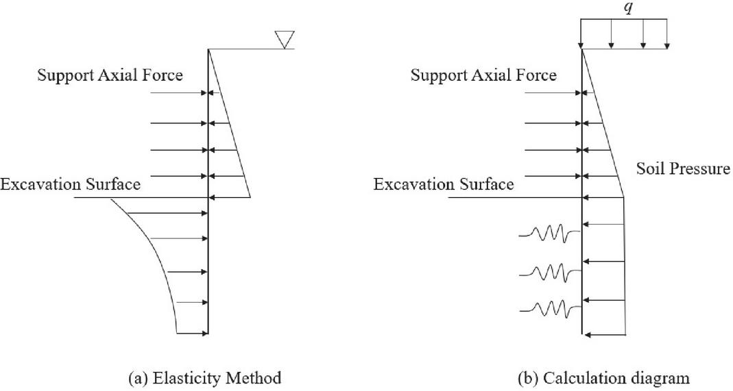
Figure 1 Planar elastic foundation beam method.
The common analytical technique and classical evaluation technique can rarely meet the wishes of basis slope help design, and the most important evaluation strategies of basis slope assist sketch are the elastic basis beam approach and finite thing method. The calculation format of the airplane elastic basis beam approach is proven in Figure 1(b), the width path of the guide shape is assumed to be a vertically positioned elastic basis beam, the spring shows the aid and anchor cable, and the regarded soil and water stress is uniformly allotted on the backyard of the aid structure.
The length of the support structure is and its deformation equation:
| (1) | |
| (2) |
Where is the flexural stiffness of the enclosure structure; is an nth excavation depth; is the active soil pressure at depth; is a lateral displacement of an enclosure structure; is the elastic beam depth; is the proportional coefficient of horizontal resistance of the basic soil.
The pit is excavated in layers, supported by multiple channels, and the construction state changes with the excavation boundary conditions of the pit, and the displacement values calculated in steps are the calculated initial values for the next stage [10].
Spring-loaded support reaction force:
| (3) |
Where: is the bullet rigidity of the -th support; is an elastic support reaction force of the -th support; is a lateral displacement of -th support derived from the differential equation of the above equation.
The stiffness of the soil spring :
| (4) |
Horizontal bed factor:
| (5) |
method, taking and , i.e:
| (6) | |
| (7) |
If no experimental results are available for the value of , the empirical formula [11]:
| (8) |
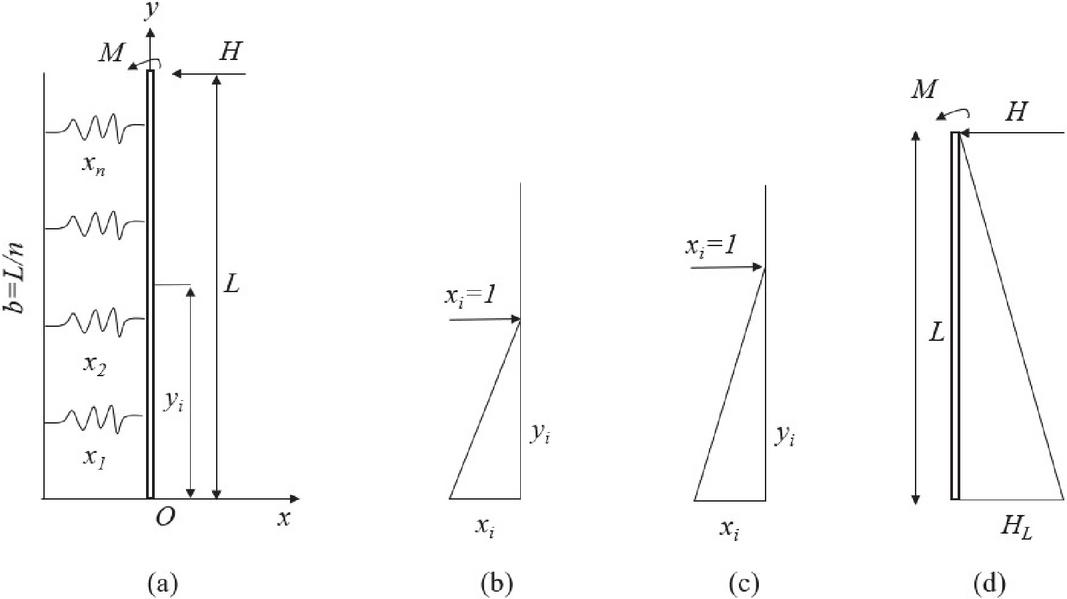
Figure 2 Simplified method calculation sketch.
2.2 A Simplified Approach to Structural Mechanics of Pile-anchored Structures
At present, the method of solving elastic foundation beams based on winkle assumption is still complicated, and for the case of layered soils, the rod system finite element method is generally required, a new simplified method proposed in this paper for the solution of elastic foundation beams [12]. As shown in Figure 2, a unit width of retaining structure is taken as a vertical elastic foundation beam, and the effects of support or anchor rod and soil mass on the foundation beam are replaced by a series of springs . For the foundation beam under the action of each spring force , the displacement coordination equation at the supporting points of each spring is as follows [13]:
| (9) |
Where: is the displacement of the foundation beam at under the action of , which is the flexibility coefficient; is the level displacement of the girder at point ; is the angle of rotation of the beam at point ; is the displacement of the beam at under the action of external forces such as bending moment and horizontal force . Each coefficient can be derived based on the structural mechanic’s method according to Figure 2(b) to 2(d). Where.
| (10) | |
| (11) | |
| (12) | |
| (13) |
Where: is the flexible mode of the base beam; is its cross-sectional inertia moment; is the bending stiffness of the foundation beam.
There are unknowns in Equation (9), but only equations are available. Therefore, the solution is supplemented by 2 equations for the equilibrium of forces [14]:
| (14) | |
| (15) |
Equations (14), and (15) can be abbreviated as
| (16) | |
| (17) |
Combining the deformed coordination equation, the following solution equation is obtained:
| (18) |
The bending moment and the shear force at any section of the foundation beam can be obtained by the section method by solving , , and tan.
The displacement of the foundation beam at an arbitrary spring is
| (19) |
Unlike the linkage method, for the determination of the soil spring stiffness , it is simplified to the Boussinesq solution to determine [15]. The force of any soil spring is and the area is ; is the soil spring spacing; is the width of the foundation beam. The concentrated force of the soil spring becomes the distributed force as
| (20) |
Then the deformation of the soil at the soil spring, approximated by Boussinesq, is
| (21) |
where and are the Poisson’s proportion and deformation mode at the soil spring, respectively. Contingency.
| (22) |
Then the stiffness of the earth spring can be defined according to the definition of spring stiffness.
| (23) |
where: is the shape factor related to , and when . In this way, the soil spring stiffness can be approximated by the deformation modulus and Poisson’s ratio of the soil; , are both geometric parameters. The physical and mechanical significance of , parameters are clear, and their determination can be approximated by the pressure plate test, etc. It is more convenient than the usual method of determining the foundation parameters in the method by using the horizontal load test of piles, and for layered soils can be reflected by the , in different soil layers. And it is more complicated to determine the value by testing for different soil layers, so it is more suitable for the current geological conditions where the soil layer is usually in a stratified situation.
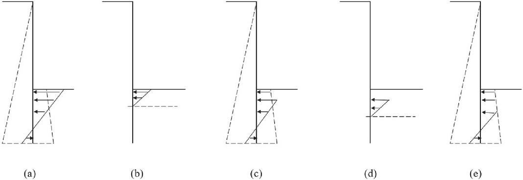
Figure 3 Calculation model of the depth of entry.
2.3 Calculation of Force Depth
How to reasonably determine the force depth of the support structure into the pit below the bottom is a more important issue, the force depth is too deep will expand the funding and building difficulty, making the building length grow; whilst the depth of entry is too shallow, and it is challenging to make sure safety. In the past, the entry depth used to be typically decided by means of thinking about the stability of the passive earth strain of the soil in the front of the pile [16]. In practice, the pile of the front soil may additionally no longer attain the passive earth stress value, due to the fact the pile of the front soil resistance is associated with the displacement of the pile. On the other hand, if the pile-front soil reaches the passive earth pressure, large displacements may occur. Therefore, the common methods are to add an empirical value of 20% after the active and passive earth pressures reach equilibrium or to take a discounted value of the passive earth pressure, which lacks a sound theoretical basis. The literature proposes a better solution, the stress transfer method, which is based mainly on the support structure’s movement and the distribution of soil reaction forces in front of the pile to determine a reasonable entry depth of the structure [17]. The idea is: The passive soil pressure is taken as the limit value of the soil reaction in front of the pile, and the excess part is transferred to the soil that does not exceed the passive earth pressure. The iterative calculation process is shown in Figure 3. If the soil resistance exceeds the passive earth pressure, the excess part will be transferred to the soil that does not exceed the passive earth pressure through iterative calculation until all the resistance is within the envelope range of the passive earth pressure. As a result, the real elastic-plastic force distribution of the soil before the pile can be obtained, as shown in Figure 3(e), when the soil resistance reaches or exceeds the passive soil pressure, the support structure will be unstable and the iteration will not converge, and the displacement of the support structure will be large; when the cantilever structure is used, the phenomenon of tipping will occur; When there is support, the usual “kick” phenomenon will occur. Therefore, through calculation and analysis, we can not only get the real distribution of the elastic-plastic resistance of the soil in front of the pile, but also can obtain the definition of the support construction reflecting the elastic-plastic state of the soil before the pile, and its stability can be judged from the distribution of the resistance [18]; the deformation of the support structure can be controlled from the displacement of the support construction and the buildings near the foundation pit, so as to adjust its entry distance. Therefore, it is a relatively complete analysis method.
2.4 Calculation of Prestressing Anchor or Prestressing Support Structure and Support Removal
In some deeper foundation pit support, the method of prestressing anchor or adding prestressing in the support is often used to control the displacement of the support structure. In fact, the stress and deformation of the supporting structure under the action of prestress force are different from those without prestress. However, the design and calculation of prestress usually lack a reasonable method, and the analysis of prestress effect is usually not deep enough [19]. The design and calculation of prestressed bolt and other supporting structures can be carried out by the incremental method above.
There are three main functions of prestress, one is to reduce the lateral displacement of the supporting structure; Second, the internal force of the supporting structure can be adjusted; Third, it can give full play to the role of bolt with small stiffness and high strength. The calculation of the prestressing effect by the incremental method can be illustrated in Figure 4(a) with one layer of anchors. When calculating the prestressing effect, it is sufficient to calculate the process of adding prestressing as an incremental step, and the load increment is the prestressing force , which is equivalent to the soil spring on the retaining side supporting the prestressing force. The incremental calculation is shown in Figure 4(a), and the result of this incremental step is iterated to the previous calculation to obtain the real result of internal force and transformation of the support construction after considering the prestressing effect. Similarly, it is only necessary to calculate the removal of the support as an incremental step, while its incremental load is the counterforce of the support force of the removed support, and the increased floor slab, etc. is taken as the newly added support. The incremental calculation process is shown in Figure 4(b), and the result of this incremental step is iteratively added to the previous calculation result to obtain the result of force change of the support structure after the support removal. Taking prestressed anchor as an example, Figure 5 indicates a contrast of the calculation effects of a mission with one layer of anchor in a preserving pile, Figure 5(a) suggests the end result of making use of one hundred twenty KN horizontal prestressing, and the horizontal displacement of pile pinnacle is 36 mm. Figure 5(b) suggests the end result except prestressing, and the horizontal displacement of the pile pinnacle is ninety mm, which indicates that prestressing can minimize the displacement of the pile pinnacle. The reaction force of the pile top anchor is the result of not iteratively adding prestressing, that is the new reaction force due to the excavation process.

Figure 4 Sketch of the calculation process of the incremental method.
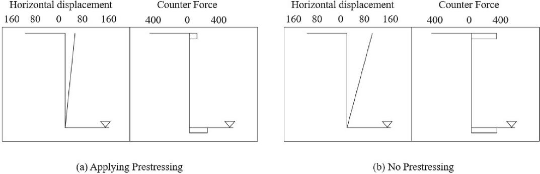
Figure 5 Comparison of displacement and reaction force effects with and without prestressing.
3 Deep Foundation Pit Monitoring
3.1 Monitoring Purpose
Pit monitoring techniques are used all the time in the implementation of foundation pit projects, which generally involve the use of scientific equipment to monitor the site conditions and focus on the state of the monitored objects [20]. In order to make the pit study of significant practical value, it is necessary to screen the data reflecting the actual conditions of the pit and identify valuable data. In previous foundation pit projects, the enclosure structure system and adjacent environment were mainly monitored. The specific purposes are as follows:
(1) To display the modifications of basis pit engineering and furnish protection for the protection of adjoining constructions (buildings) and basis pit help structures. Based on the monitoring effects to make a pre-judgment of the risky fashion or risk of occurrence, so as to make an ordinary judgment on the protection of the project, and to do a proper job in the prevention of security dangers and accident probabilities of nearby structures or structures, basis pit engineering, so that the hassle can be decided in time beneath the prerequisites of the prevalence of the response strategy.
(2) Based on the monitoring results to provide guidance for on-site construction, the feedback optimization design (informatization), so as to ensure that the design scheme is moderate in duration, reasonable in cost, safe, and stable.
(3) Comparison of theoretical calculation values and site monitoring results, followed by reverse analysis, will be more accurate design parameters to obtain, so as to amend the original theory, and formula, to enhance the field construction operation guidance effect, for similar engineering design, construction practice to provide theoretical reference basis.
3.2 Monitoring Design
According to the support form and site construction conditions adopted in this project, 6 monitoring sections are designed, numbered AF, and their positions in the pit are as follows: section 3-3 at the south end of the east side of the pit; section 4-4 at the east end of the south side of the pit; section 8-8 at the west end of the north side of the pit; section 10- 10 at the west side of the building; section 12-12 at the middle section of the north side of the pit near the building; section 14-14 at the middle section of the north side of the pit near the building (it is a section immediately adjacent to section 12-12, and this section is an additional test section).
The top of the crown beam or the top of the side slope of the foundation pit, which is about 30–50 cm away from the pit side, is suitable for the observation point of pile top horizontal displacement. The total station distance method is usually more suitable for the observation of pile top and foundation pit supporting structure horizontal displacement. The basic principle of the total station distance method is to set the observation point on the crown beam or pier, and then use the high precision distance measuring total station as the basic observation equipment to observe the distance between the observation points, and the deformation and displacement value is the change value of two observation distances. If the observation point cannot be kept perpendicular to the line of sight, the direction should be checked.
According to the design plan and drawings provided by the construction unit, the excavation depth of the pit at each monitoring section is 22.55 n. Based on the above, 12 pile stress gauges are buried in section A, and 1 anchor head tension sensor is installed at each of the 1st, 2nd and 3rd anchor rods; 12 pile stress gauges are buried in section D, and 1 anchor head tension sensor is installed at each of the 1st and 3rd anchor rods; 13 pile stress gauges are buried in section E, and 1 anchor head tension sensor is installed at each of the 1st, 2nd and 3rd anchor rods; 13 pile stress gauges are buried in section F, and 1 anchor head tension sensor is installed at each of the 1st, 2nd and 3rd anchor rods. In section E, there are 13 pile stress gauges and 1 anchor tension sensor at each of the 1st, 2nd and 3rd anchor rods; in section F, there are 13 pile stress gauges and 1 anchor tension sensor at each of the 1st, 2nd and 3rd anchor rods; in section C, there are 23 measurement points in the soil nail wall.
4 Force Calculation Reasonableness Verification and Factor Analysis
4.1 Verification of Force Calculation Method for the Support Structure
The primary general of information-based basis excavation and aid development lies in the dynamic monitoring of basis help shape based totally on on-site measurement, which affords theoretical instruction for excavation exercise and guide shape development [26]. A fundamental way of basis pit guide monitoring lies in suitable on-site measurement so that it can have well-timed and correct perception and mastery of dynamic deformation of basis pit, successfully draw close the steadiness of guide structure, and make a judgment on the reliability of help system: provider guide layout and assist building decision. Another necessary characteristic of pit monitoring is that it can correctly right and enhance the deficiencies in the preliminary design, and information on the excavation of the pit and alter quite a number of discomforts in the excavation exercise in time. Therefore, all components of basis pit guide development have to be applied in the total technique of help monitoring.
There are many uncertainties in the sketch and building of basis pits. Most of them are confined by using the building website and will have an extra impact on the adjoining present structures. Therefore, the exercise of basis pit engineering has to first off furnish a simple warranty for the security of the basis pit and assist structure, and secondly make sure that the everyday use or operation kingdom of quite a number of structures, constructions, and roads in the neighborhood is no longer affected in any way. Therefore, the use of pressure calculation evaluation earlier than the excavation of the basis pit suggests the vital engineering significance, evaluation, and finding out about the deformation traits of the basis pit challenge in the excavation process, the opportunity of the surroundings affected through the excavation of the basis pit, specifically for the prediction of the protection and everyday use of the surrounding necessary structures or constructions is of wonderful importance. This will information on the venture graph and construction.
Table 1 Comparison of soil settlement
| Depth | Monitoring Value | Calculated Value | Depth | Monitoring Value | Calculated Value |
| 0 | -2.79629 | -1.92237 | 45 | -10.2233 | -11.0388 |
| 3 | -7.45812 | -5.12807 | 48 | -9.81746 | -9.8175 |
| 6 | -9.38257 | -7.57679 | 51 | -9.81953 | -9.00399 |
| 9 | -11.3068 | -9.85045 | 54 | -9.47183 | -8.42324 |
| 12 | -14.7456 | -11.7747 | 57 | -9.53202 | -8.07563 |
| 15 | -15.3885 | -13.6408 | 60 | -9.00974 | -7.67006 |
| 18 | -21.0407 | -17.5455 | 63 | -8.83701 | -7.67192 |
| 21 | -23.431 | -19.8775 | 66 | -8.02338 | -7.3826 |
| 24 | -26.4041 | -21.9767 | 69 | -6.68569 | -7.26812 |
| 27 | -25.9982 | -23.3184 | 72 | -6.33794 | -7.26998 |
| 30 | -25.7671 | -23.4369 | 75 | -6.04871 | -7.03891 |
| 33 | -25.4779 | -22.6235 | 78 | -6.10878 | -7.15741 |
| 36 | -23.499 | -20.2369 | 81 | -5.936 | -7.10105 |
| 39 | -17.9088 | -15.8116 | 84 | -5.87991 | -7.16142 |
| 42 | -16.5127 | -12.8428 | 87 | -5.41575 | -7.16323 |
It can be seen from Table 1 above that the characteristic trend of soil settlement change under the calculated values in this paper is consistent with the monitored values, both of which show a “belly” characteristic curve. The maximum settlement deformation calculated by this method occurs 30 m away from the pit edge, and the deformation is 23.437 mm. The maximum settlement deformation occurred 25 m away from the pit edge, and the deformation was 26.517 mm. The difference between them is 3.08 mm, which is small. The surface numerical simulation can accurately represent the settlement change of soil around the foundation pit.
As can be observed from Table 2 below, the horizontal variation characteristics of the envelope are the same for the calculated and monitored values in this paper, and the maximum deformation of both is shown in the area from the lowermost to the anchor cable to the bottom of the pit. The maximum value calculated by this method is 17.494 mm, and the maximum value monitored is 23.988 mm, and the extreme difference between the two is 6.494 mm, although there is a certain error, the overall deformation law of the two remains consistent, and the calculation method of this paper can still provide some reference value.
Table 2 Comparison of horizontal displacement of enclosure structure
| Depth | Monitoring Value | Calculated Value |
| 0 | -17.3282 | -12.929 |
| 2 | -19.3064 | -13.5657 |
| 4 | -20.5898 | -14.3133 |
| 6 | -20.7475 | -15.0611 |
| 8 | -23.8554 | -15.9154 |
| 10 | -23.7447 | -16.8778 |
| 12 | -23.4191 | -17.5717 |
| 14 | -23.791 | -17.568 |
| 16 | -22.4998 | -16.3302 |
| 18 | -21.1016 | -9.78168 |
| 20 | -10.0444 | -3.01684 |
| 22 | -0.65089 | -0.22177 |
Following the digging of the foundation pit, the settlement characteristic curve of the surrounding surface showed a “belly shape” and was uniformly distributed along the depth direction. It is analyzed that this is mainly due to the increasing soil pressure behind the surrounding pile body as the opening surface of the foundation pit deepens. And the pile body is in an elastic working condition, caused by the weak constraint in the center of the pile body, resulting in higher deformation in the middle and coordination of the soil outside the pile due to deformation. Therefore, the overall surface settlement characteristic curve in the surrounding area shows a “belly shape” and continues to increase with the increase of later working conditions, showing a dynamic change process.
As the digging surface of the foundation pit deepens, the horizontal distortion of the surface outside the pit shows a pattern pointing to the inner part of the pit. This is because when the excavation of the pit is unloaded, the support structure produces deformation pointing in the pit, and the earth outside the pile also exhibits horizontal deformation pointing in the pit due to the coordination of deformation.
4.2 Analysis of Influencing Factors
The single-factor analysis is conducted while keeping other detailed design factors constant. To study the effects of anchor cable pre-stress size, anchor cable inclination angle, anchor cable anchorage section length, pile clear spacing, pile diameter, pile length, and other related factors on the deformation and force characteristics of the support structure. To provide a reference for the orthogonal test to determine the reasonable interval of each detailed parameter.
(a) Effect of pile diameter variation on the pile-anchored support structure
The pile diameter measurement of the assisting pile has an exceptionally giant effect on the protection of the basis pit. Keeping the excavation depth of the basis pit at 12 m, the pile size at 24 m, placing two anchor cables, and the pile spacing at 1.3 m, solely the diameter dimension of the aiding pile is modified to evaluate the impact of the helping pile on the lateral displacement of the pile below exclusive diameters. Assuming that the diameter measurement of the assisting pile is 600 mm, 800 mm, 1000 mm, and 1200 mm in order, the bought affect pile displacement curve is proven in Figure 6(a).
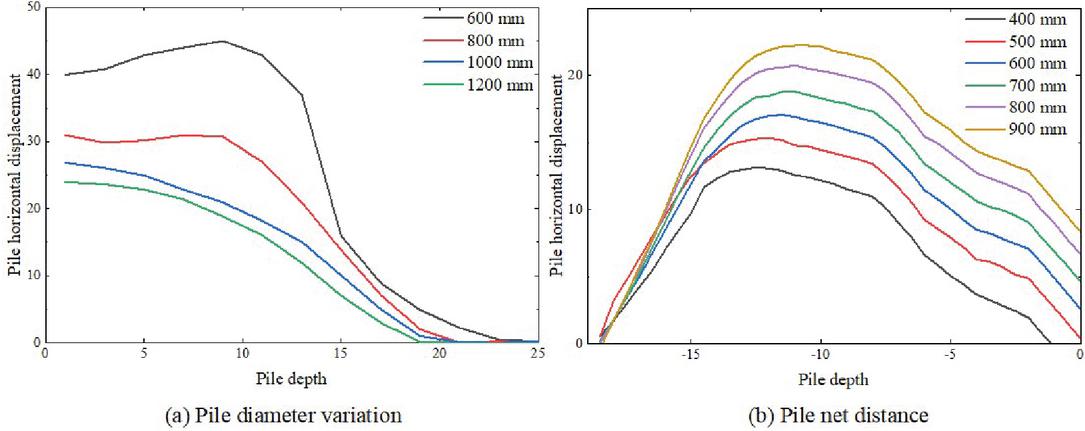
Figure 6 Effect of pile diameter variation and net pile spacing on pile displacement.
From Figure 6(a), we can see the impact of pile diameter exchange on the horizontal movement of the pile. When the pile diameter is 800 mm, the most horizontal movement of the pile physique is 30.89 mm, which seems at the pinnacle of the pile, and the movement curve of the pile physique is “small belly”; when the pile diameter is extended to 1000 mm and 1200 mm respectively, the most horizontal movement of the pile physique is decreased to 27 mm and 24 mm respectively, which seems at the pinnacle of the pile, and the movement curve of the pile physique is “golden cup”. The pile displacement curve is in the structure of a “golden cup”.
(b) Effect of net pile spacing on pile anchor support structure
The single-factor analysis is carried out while keeping the other detailed design factors unchanged. Since the support form of one pile and one anchor is used, changing the net pile spacing will also indirectly cause the change of horizontal spacing of the anchor cable. From Figure 6(b), the horizontal displacement of the row of piles is massive in the center and small at each end when the internet pile spacing of the row of piles is different. From Figure 6(b), the horizontal displacement of the pile will increase with the amplification of internet pile spacing and the top of the pile strikes out of the basis pit. When the internet pile spacing is 400 mm, the most horizontal displacement of the pile is 13.13 mm, and when the internet pile spacing is 900 mm, the most horizontal displacement of the pile is 22.23 mm. Within a positive range, lowering the internet pile spacing is suitable for controlling the deformation of the basis pit. Moreover, engineering exercise proves that if the internet pile spacing is too large, the soil between the piles can also slide locally, which is a chance for the security of the development employees at the backside of the pit, and there is additionally a danger of neighborhood instability of the pit.
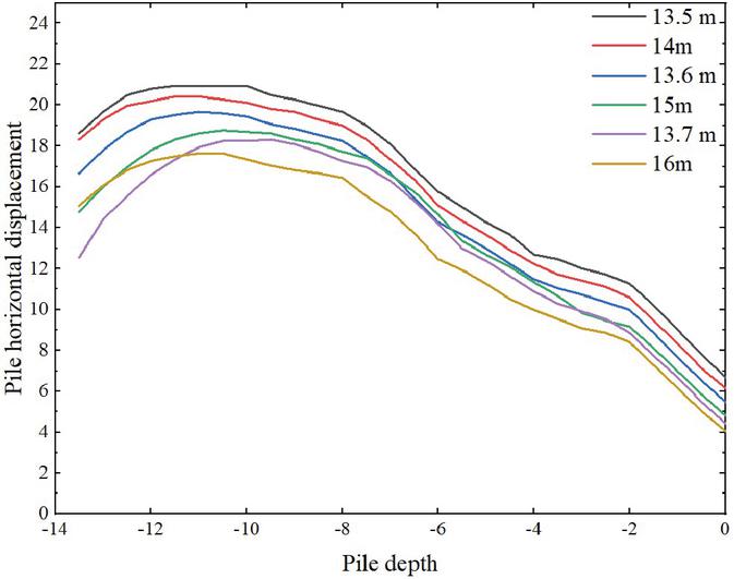
Figure 7 Effect of different pile lengths on pile displacement.
(c) The influence of pile length on the pile-anchor support structure
Single-factor analysis was performed while keeping other detailed design factors constant. From Figure 7, it is recognized that when one-of-a-kind pile lengths are used for the row piles, the horizontal displacements of the row piles are all massive in the center and small at each end. From Figure 7, it is acknowledged that the most horizontal displacement of the pile decreases steadily as the pile size increases, however, when the pile size is longer than 15 m, the charge of trade of horizontal displacement of the row pile slows down. When the pile size is small, the guide shape is effortlessly destabilized and can’t meet the necessities of protection design. However, it is now not viable to expand the pile size blindly. When the pile size reaches a sure level, persevering to make bigger the pile size will enhance the deformation of the row pile solely to a constrained extent and waste the challenge cost.
(d) The effect of anchor cable prestress size on pile anchor support structure
In the excavation depth of the foundation pit is 12 m, two anchor cables are set at 3.5 m and 6.5 m, and only the size of anchor cable pre-stress is changed, and the same pre-stress is taken for both anchors when 10 KN, 100 KN, 300 KN, and 3000 KN are taken respectively, the simulation results of lateral displacement of supporting pile are shown in Figure 8(a).
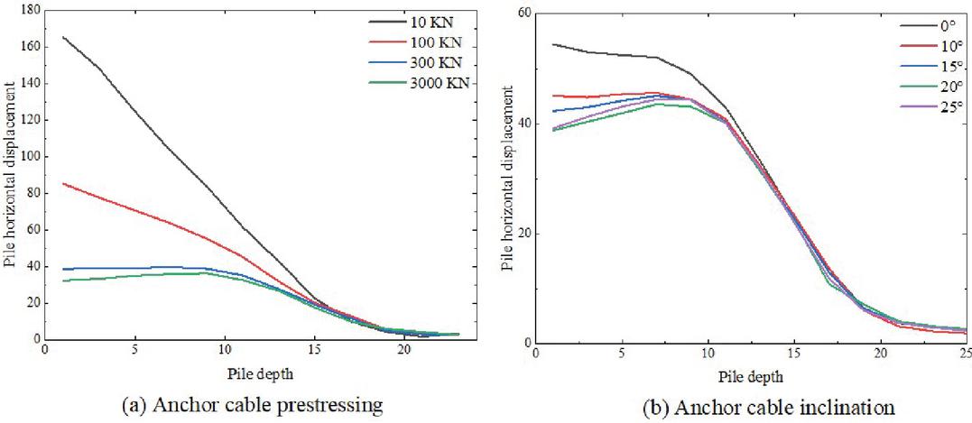
Figure 8 Effect of anchor pre-stressing and inclination angle on pile displacement.
From Figure 8(a), it can be viewed that the magnitude of anchor cable prestresses has a first-rate an effect on the horizontal movement of the pile. When the prestress of two anchor cables is 10 N, which is equal to no prestress applied, the horizontal movement of pile pinnacle reaches 165 mm and the enclosing pile is about cantilevered, indicating that the anchor cables barring prestress utilized have little impact on the horizontal movement of pile, which is nearly negligible; when the prestress of anchor cables is 100 N, the horizontal movement of pile pinnacle reaches 85 mm, which is drastically much less than the horizontal movement of pile pinnacle with prestress of 10 KN. When the anchor prestress continues to extend to 300 N, the horizontal movement of the pile pinnacle is decreased to 39 mm, which is 46 mm much less than the horizontal movement of the pile pinnacle with 100 KN prestress, which indicates that the make bigger of anchor prestress performs an vital restraining impact on the horizontal movement of the pile; when the anchor prestress is 3000 N, the horizontal movement of the pile pinnacle reaches 33 mm, and the impact is comparable to 300 KN. At this time, we solely want to follow 300 KN prestress. It additionally suggests that the anchor shaft pressure (or pullout resistance) is limited.
(e) Effect of anchor cable inclination angle on pile anchor support structure
Since the alternate anchor inclination attitude impacts the horizontal inside pressure of the anchor rod and the measurement of horizontal displacement of the basis pit, it must be paid interest in the plan and development of pile anchor guide shape of deep basis pit. When the pile diameter is 1.0 m, the excavation depth of the pit is 12 m, and the anchor inclination attitude is 0, 10, 15, 20, and 25 respectively, as proven in Figure 8(b).
From Figure 8(b), it can be seen that altering the anchor cable inclination perspective will have a sure impact on the horizontal movement of the pile. When the anchor cable inclination attitude is 0, the most horizontal movement of the pile is 55.6 mm at the pinnacle of the pile, and when the anchor cable inclination attitude will increase to 10, the most horizontal movement of the pile is 45.5 mm at 7 m. When the anchor cable inclination perspective is 15, the most horizontal movement of the pile is 45 mm, which takes place at the function of 7 m. When the anchor cable inclination perspective is 20, the most horizontal movement of the pile is 43.5 mm, which takes place at the role of 7 m. When the anchor cable inclination attitude is 25, the most cost of horizontal movement of the pile is 44.6 mm, which seems to increase. The most price of horizontal movement of the pile essentially takes place at the role of about 7 m.
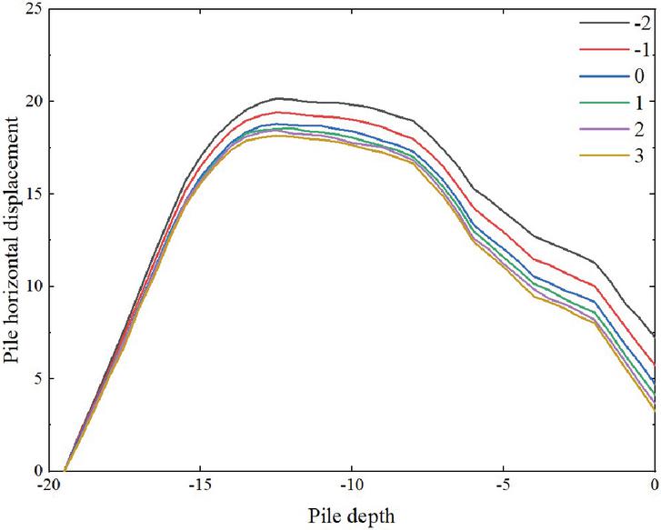
Figure 9 Effect of different anchorage lengths on pile displacement.
(f) Effect of anchor cable anchorage section length on pile anchor support structure
A single-factor analysis was conducted while keeping other detailed design factors constant. As can be observed from Figure 9, when the length of the anchor cable anchorage section is different, the horizontal displacement of the row pile is large in the middle and small at both ends. From Figure 9, it can be seen that the maximum horizontal movement of the row pile decreases with the growth of the anchor cable anchorage section length; when the anchor cable anchorage section is small, the effect of increasing the movement of the row pile is obvious, and the decline rate slows down with the increase of the anchor cable anchorage section length, if the movement of the row pile is controlled simply by raising the anchor cable anchorage section length, the effect is not obvious and the project cost is wasted.
4.3 Orthogonal Combination Optimization Scheme
Based on the practical situation of the project, factors that have an obvious influence on the test results are selected for analysis as far as possible. For the optimal design of “pile-anchor” supporting structure, the factors affecting the evaluation index mainly include: pile diameter, pile spacing, pile length, cable prestress, anchoring section length and bolt Angle. The relationship between factors and indicators is similar to that between independent variables and dependent variables. For the multi-indicator problem of the orthogonal test in this paper, the optimization schemes with the horizontal movement of the pile row and the cost per extended meter of the base pit as the optimization indicators respectively are contradictory, making it difficult to compare the optimization schemes with each other. In order to make the orthogonal test have the basis of comparison, this paper establishes the affiliation function of each evaluation index based on the relevant concept of fuzzy mathematics to calculate the affiliation degree of a fuzzy comprehensive evaluation for the multi-index orthogonal test, converting multiple indexes into single indexes and making the orthogonal test have the basis of comparison. The factor level corresponding to the maximum value of the average fuzzy comprehensive evaluation affiliation is used as the optimal design solution as: mm, t 700 mm, H 14.5 m, F 240 kN, H 1 m.
Among the evaluation factors, the maximum horizontal lateral displacement of the pile and the cost per linear meter of the foundation pit are small indicators, which means that the smaller the better, so the affiliation function can be established.
| (24) |
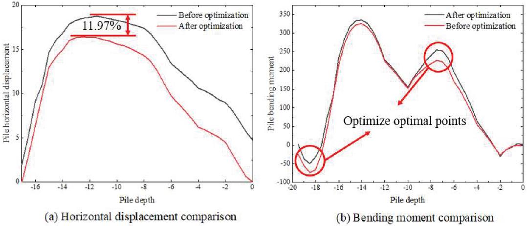
Figure 10 Comparison before and after optimization.
As in Figure 10, the optimized maximum horizontal movement of the row pile is 16.505 mm, which is 11.97% less than the original design maximum horizontal movement of 18.75 mm, and the maximum horizontal movement of the row pile is significantly lower. The largest flexural moment of the optimized row pile is 336.87 kN-m, compared with the maximum flexural moment of 327.18 kNm of the original design, it is increased by 2.96%, and the change of flexural moment is not obvious.
5 Conclusion
In this paper, the force calculation model of pile-anchor support structure based on the elastic foundation beam method is proposed. In combination with a deep foundation pit project in China, the calculation method derived from the simplified elastic foundation beam method and the structural monitoring method are used to compare and study the force characteristics and safety of the deep foundation pit anchor support structure system. Factors such as anchor cable anchorage section length, pile diameter, pile length, net pile spacing, and anchor cable prestress are used as design variables to solve the problem of multiple contradictory indicators, and an optimization scheme is proposed using orthogonal combinations. The specific conclusions are as follows:
(a) In this paper, the support structure is simplified as a vertical elastic foundation beam, and the support, anchor and geotechnical body are replaced by a spring system, and a simplified mechanical model of the pile-anchor structure is proposed, and then a systematic method of calculating the internal force of the pile-anchor support structure is derived, which also includes the reasonable determination of the depth of the support structure into the soil and the calculation of pre-stress and support removal.
(b) The maximum settlement deformation of the calculated value is 23.437 mm and the maximum settlement deformation of the monitored value is 26.517 mm, and the extreme difference between the two is 3.08 mm, both of which are negligible. Analysis of the influence law of each factor on the maximum horizontal displacement of pile anchor shows that: the net pile spacing, anchor cable prestress size, and pile diameter has a relatively large influence on the horizontal displacement of the pile, the length of anchor cable anchorage section, the pile length has the second influence.
(c) The orthogonal combination of five factors was optimized and the optimized design was obtained as: mm, t 700 mm, H 14.5 m, F 240 kN, H 1 m. The maximum bending moment of the optimized row pile was 336.87 kNm and the maximum horizontal displacement of the pile was 16.505 mm, which was reduced by 11.97%.
There are many factors influencing deep foundation pit support, such as pile length, bolt length, dip Angle, excavation depth under various working conditions, etc. This paper simply discusses the influence rule of individual factors on the maximum horizontal displacement of pile and anchor, without considering combination. By changing the influencing factors and discussing the state of the foundation pit supporting structure and soil under different conditions, the future research direction can conduct in-depth research on the relationship between the factors inside the deep foundation pit.
References
[1] Sun Y, Xiao H. Wall displacement and ground-surface settlement caused by pit-in-pit foundation pits in soft clays[J]. KSCE Journal of Civil Engineering, 2021, 25(4): 1262–1275.
[2] Zhu Guichun, Liu Xingxin, Han Wujuan. Study on force deformation and optimal design of pile-anchor support system for deep foundation pits[J]. Safety and Environmental Engineering, 2012, 19(1): 124–128.
[3] He Meide, Le Guiping, Liu Jun, et al. Analysis of force and deformation characteristics of a foundation pit enclosure structure in Olympic Park[J]. Journal of Geotechnical Engineering, 2008 (S1): 582–587.
[4] Yang T, Li Y, Zhai X. Seismic Performance Analysis of Reinforced Concrete Frame Structures Based on Computational Mechanics[J]. European Journal of Computational Mechanics, 2021: 99–120.
[5] Yang Z. F., Zhu Y. P., Guo N., et al. Experimental study on the internal forces of pile-anchor support structures in deep foundation pits of subway stations[J]. Geotechnical Mechanics, 2014, 2.
[6] Wang T, Wüchner R, Bletzinger K U. Assessment and practical application of mapping algorithms for beam elements in computational FSI[J]. European Journal of Computational Mechanics, 2016, 25(5): 417–445.
[7] Li HW, Nie QK. Evolution of deformation and force state of pile-anchor support structure during deep foundation excavation[J]. Journal of Coal, 2011 (S2): 315–320.
[8] Mallardo V, Ruocco E. A NURBS boundary-only approach in elasticity[J]. European Journal of Computational Mechanics, 2016, 25(1–2): 71–90.
[9] Han S, Yang K, Wei X, et al. Analysis of the influence of inside and outside water level changes of foundation pit on stability of foundation[C]//2016 2nd International Conference on Architectural, Civil and Hydraulics Engineering (ICACHE 2016). Atlantis Press, 2016: 280–284.
[10] Shen Y G, Li X Q, Du N J, et al. Research on Analysis and Control of Seepage Failure in Foundation Pit[C]//Advanced Materials Research. Trans Tech Publications Ltd, 2012, 368: 3171–3174.
[11] Liu Yang. Design and stability study of pile-anchored support structure for deep foundation pit of Dingfuzhuang resettlement house in Beijing [D]. Jilin University, 2018.
[12] Zhang D D. Coupled numerical simulation research on dewatering and land subsidence in deep foundation pit[C]//Applied Mechanics and Materials. Trans Tech Publications Ltd, 2013, 275: 1549–1552.
[13] Qiu J, Li F. The Application of Foundation Pit Monitoring Technology to the Excavation[C]//MATEC Web of Conferences. EDP Sciences, 2015, 22: 04004.
[14] Yang Guanghua. Practical calculation methods for deep foundation pit support structures and their applications [M]. Geological Press, 2004.
[15] Wang Y, Fang X, Fei W, et al. Development and Application of BIM-based Foundation Pit Construction Simulation System[C]//IOP Conference Series: Earth and Environmental Science. IOP Publishing, 2021, 714(2): 022062.
[16] Nie S M, Ren F. Study on risk management of deep foundation pit engineering[C]//Applied Mechanics and Materials. Trans Tech Publications Ltd, 2014, 638: 574–579.
[17] Shao Quan, Xu Xuelian, Xu Song, et al. Three-dimensional numerical analysis of deformation influencing factors of combined pile-anchor bracing support structures in deep foundation pits[J]. Journal of Geotechnical Engineering, 2014, 36(zk2): 87–91.
[18] Zhang J X, Dai J L, Liu B. Application of Comprehensive Evaluation Method to Foundation Pit Engineering[C]//Advanced Materials Research. Trans Tech Publications Ltd, 2012, 446: 1775–1780.
[19] Yu Chenglong. Research on deformation characteristics and optimal design of a deep foundation pit pile anchor support structure in Changde [D]. Xiangtan University, 2019.
[20] Jiao S H, Wang J A, Liu Y M. Exploration and Practice of Innovative Support System of Large-Scale Deep Foundation Pit in Beijing[C]//Advanced Materials Research. Trans Tech Publications Ltd, 2014, 838: 747–755.
[21] Zheng Weifeng, Shao Longtan, Jia Jinqing. Stress distribution law and application of prestressed anchor rod anchorage section in deep foundation pit[J]. Journal of Liaoning University of Engineering and Technology: Natural Science Edition, 2008, 27(6): 862–865.
[22] Gao X, Wang W. Analysis of influence of adjacent side length of deep foundation pit on pit angle effect[C]//IOP Conference Series: Materials Science and Engineering. IOP Publishing, 2019, 592(1): 012127.
[23] Zhang C M. Applications of soil nailed wall in foundation pit support[C]//Applied Mechanics and Materials. Trans Tech Publications Ltd, 2013, 353: 969–973.
[24] Zhang Qinxi, Chen Peng, Yin Wenbiao. Monitoring study on the foundation support project of China World Trade Center Phase III[J]. Journal of Rock Mechanics and Engineering, 2012, 31(11): 2319–2326.
[25] Chen S, Cui J, Liang F. Case study on the deformation coupling effect of a deep foundation pit group in a coastal soft soil area[J]. Applied Sciences, 2022, 12(12): 6205.
[26] Chen S, Cui J, Liang F. Centrifuge model investigation of interaction between successively constructed foundation pits[J]. Applied Sciences, 2022, 12(16): 7975.
Biographies

Han Lingjie received the master’s degree from Changsha University of Science & Technology in 2013. He is currently working as an associate professor of Zhengzhou University of Science and Technology. His main research fields and directions include subgrade and pavement design and BIM technology application.

Zhang Shihao obtained a bachelor’s degree in engineering from Liaoning University of Science and Technology in 2016, and a Master of Engineering degree in engineering from Chang’an University in 2019, currently works as an assistant teacher in the Railway Engineering School of Zhengzhou Railway Vocational and Technical College. His research fields and directions include subgrade and pavement, road disaster prediction and treatment, and new materials for construction engineering.

Tang Huarui received the bachelor’s degree from Wuhan University of Technology in 2006, the master’s degree in engineering from Zhengzhou University. She is currently working as an associate professor of Zhengzhou Railway Vocational and Technical College. Her main research fields and directions include subgrade and pavement design and BIM technology application.
European Journal of Computational Mechanics, Vol. 32_2, 183–210.
doi: 10.13052/ejcm2642-2085.3224
© 2023 River Publishers