Investigating the Effect of Brickwork Patterns on Response of Masonry Walls Under Blast Load
Sipho Gcinangaye Thango1,*, Siphesihle Mpho Motsa1, Georgios E. Stavroulakis2 and Georgios A. Drosopoulos1, 3
1University of KwaZulu Natal, Department of Civil Engineering, Durban 4041, South Africa
2Technical University of Crete, School of Production Engineering & Management, 73100 Chania, Crete, Greece
3Department of Civil Engineering, International Hellenic University, Serres, 62124, Greece
E-mail: 209523102@stu.ukzn.ac.za; thangosiphog@gmail.com
*Corresponding Author
Received 18 October 2023; Accepted 26 March 2025
Architects consider the brickwork patterns vital for the aesthetics of the walls. The different brick bonding patterns can influence the resistance of masonry walls when subject to in-plane and out-of-plane loading. This study investigates the effect of different bonding patterns under a blast load of 50 kg TNT at a standoff distance of 20 m. Advanced non-linear finite element models were adopted, considering unilateral contact-friction and continuum damage mechanics laws, to capture different failure types. The adoption of a simplified micro-modelling approach provided meaningful results on the behaviour of the wall. The in-plane and out-of-plane response of walls with different bonding patterns was investigated and comparisons were made. This study concluded that the stack bond has a weaker binding pattern than other widely used bonds like English bond and Stretcher bond due to the lack of interlocking between the masonry units. Shear failure and vertical cracking were seen as the typical failures in all the three walls, with the stack bond depicting higher deflections under both in-plane and blast loading.
Keywords: Blast, masonry, mortar, in plane, out of plane, brick patterns.
The orientation of bricks in masonry wall construction is regarded as one of the aspects that architects consider vital for the aesthetics of the walls. In Debnath et al. [1], it was investigated how unreinforced masonry (URM) wall components function under lateral or typical seismic loads with each of the four types of brick bonds: Header bond, Stretcher bond, English bond, and Flemish link. In Shrestha et al. [2], it was concluded that the URM walls made with English and Flemish bonds show almost 1.2 times the load-carrying capacity exhibited by the walls made by Header and Stretcher bonds. The study presented in Bacigalupo et al. [3] assessed the in-plane behaviour of Header, Stretcher, and English bonds using parametric micro-modelling. The conclusions from this study were that the header bond portrayed higher lateral capacity together with equal shear capacity as that of English bond. In Shah et al. [4], tensile-compressive loads were applied to masonry walls leading to the following fundamental distinctions: the herringbone pattern’s tensile strength attributes seem to be significantly higher than the comparable strength of its constituent parts.
Thango et al. [5] studied the failure response of masonry walls subjected to blast loading using nonlinear finite element analysis. This study considered the stretcher bond pattern. Explosive weights of 100 kg TNT, 200 kg TNT and 1150 kg TNT were considered with the varying standoff distances which included distances such as 20 m, 50 m, and 100 m. This study highlighted the effect of the standoff distances and blast weight on the damage intensity, the closer the explosive, the higher the damage intensity.
According to Elmenshawi et al. [6] it is necessary to characterize the mechanical properties of masonry, such as strength and stiffness, to comprehend how it behaves as a structural material. The stress-strain relationship is often defined or expressed by the material constitutive law that is defined over the range of applicability of the material being considered. In the modelling approach herein proposed, the masonry units are taken as continuum elements and mortar joints as interface elements. Zero tensile resistance between the joints was introduced (Mortar properties were not introduced or defined).
According to D’Altr et al. [7], Pasquantoniog et al. [8] and Stankowski et al. [9] each mortar layer is continuously linked to a brick and separated by an interface from other bricks. Weyler et al. [10] highlights that the in the zero-thickness interfaces between the Representative Elements, the contact penalty approach is used. Conventional point-against-surface contact method is considered. In such modelling, the penalty stiffness is assumed to keep insignificant the penetration of the elements and to pledge good convergence rates of simulations. For the 3D model, a rigid infinitely resistant behaviour for bricks was assumed, whereas for joints a Mohr-Coulomb failure criterion with the same tensile strength and friction angle used in the homogenized approach for joints was adopted. Eight-noded (hexahedron) brick elements were utilized both for joints and bricks, with a double row of elements along wall thickness.
However, the influence of brick patterns has not yet been thoroughly investigated. In the present paper, the static and dynamic behaviour of masonry wall with different types of brick bonding is investigated computationally. The wall is analysed using both in-plane and out of plane loading, and one of the out of plane loading considered in this case is blast loading. Blasting can arise from various activities including mining activities that involves breaking of rocks. Blasting is a crucial aspect of mining operations that involves the use of explosives to break down hard rock formations and access valuable minerals. Explosions and bombing scenes also put residential houses at risk of damage.
Finite element analysis was adopted in this study to model different brick bonding patterns and boundary conditions. Non-uniform blast loads were considered. Changes in displacement time histories and plastic hinge formations resulting from varying the axial load were examined. The breakdown of brick-mortar bonding, which introduces planes of weakness, is typically a major factor in the mechanical behaviour of masonry buildings that are on the verge of collapsing [11]. Accordingly, in this paper nonlinear numerical analyses were performed for progressive collapse assessment. The walls with different bonding patterns were compared. Prior to conducting the numerical assessment, literature review was conducted to ascertain the available knowledge on this topic and address the research gap. This paper is organized as follows; in Section 2 of this article, an introduction to blast actions and the concept of the study are briefly discussed. In Section 3, the constitutive descriptions of the article and potential failure modes are presented. Section 4 provides the details of the proposed finite element model. Validation of the model is presented in Section 5. In Section 6, results and discussions are provided. Lastly, in Section 7, the conclusions of this investigation are presented.
Explosion is defined as a large-scale, quick, and unexpected discharge of energy. Depending on their nature, explosions can be classified as physical, nuclear, or chemical phenomena [12]. A general rule of explosives is that the detonation of the explosives results in a high-velocity shock wave and a great release of gas. This high-velocity shock and gas release has over the years been causing damages to neighbouring structures or even fatalities. With specific reference to buildings, the air-blast shock wave is the main mode that explosions cause damage.
Blast loads are produced by detonation of explosive materials. Detonation is a chemical reaction that propagates through the explosive material at supersonic speed and converts the material into pressure gas. Due to this process, a pressure wave is developed and travels in all the directions, generating a push-pull action on air. This gas pressure, also known as detonation pressure, propagates like a shock wave, and affects the surrounding structures. The demonstration of the blast loading on structures is shown in Figure 1.
Figure 1 Blast pressure and loads on a structure [13].
Aim of this study is to evaluate the structural response of masonry walls with different brick bonding patterns under static and dynamic, blast actions. An advanced non-linear finite element model is developed using commercial finite element analysis software (ABAQUS), to evaluate the response of the masonry walls shown in Figure 2 under in-plane and out of plane, blast actions. The model considers material non-linearity in the form of a concrete damage plasticity law, to capture the compressive and tensile failure on the masonry units. In addition, unilateral contact and friction interfaces are introduced between the masonry units, to depict potential failure in the form of opening and sliding between the units.
Figure 2 Different brick bond patterns: (a) stretcher bond; (b) English bond; (c) stack bond.
It is noted that in the framework of the non-smooth contact mechanics law which is considered in the proposed finite element model, a simplified representation of the mortar joint as a zero-thickness interface was adopted. The assumption of a mortar joint as a zero-thickness interface is a simplification useful in modelling the behaviour of masonry structures [14]. In reality, mortar joints have a measurable thickness, typically on the order of a few millimetres. However, when analysing the response of a masonry wall under external loads, modelling the mortar joints as zero-thickness interfaces can simplify the analysis and provide reasonable results. This is because the mortar joint has a significantly lower strength compared to the masonry units, and therefore, the joint’s thickness is often negligible in terms of the structural response of the masonry structure.
In this section, the constitutive descriptions which have been adopted in the study, namely, the contact and damage mechanics laws, are provided.
Finite element method of analysis is an advanced method which is commonly applied to solve complex structural analysis problems that include among others, blast actions. According to Lourenco [15], modelling masonry structures can be grouped into two classes: Micro-modelling and macro-modelling. As can be seen in figure 3, in micro-modelling (detailed), continuum components are used to represent the brick unit and mortar, while interface elements are used to depict the unit-mortar interaction. In the simplified micro-modelling approach, brick units are modelled as continuum elements and the unit-mortar interfaces are grouped and modelled with the interface elements.
According to Lourenco et al. [16], the macro-modelling distinction between brick/stone units and mortar joints is treated as one unit. The consideration of brick and mortar as one homogeneous material tends to make the macro-modelling techniques more suitable for practical use as the computer resource required is less when compared with micro-modelling techniques. As discussed by Braimah [17], the macro-modelling technique is not able to offer information on failure mechanism, which most often is not needed in the analysis. This is further stated by Kömürcü and Gedikli [18], by using the macro modelling approach, the detailed failure mechanisms are generally not well reproduced. Recent advances in homogenization that incorporates XFEM could enhance the effectiveness of macro-modelling in this respect, see Drosopoulos and Stavroulakis [19].
Figure 3 Modelling techniques for masonry structures (a) detailed micro-modelling, (b) simplified micro-modelling, (c) macro-modelling [15].
Figure 4 Schematic representation of the contact conditions between two masonry units.
To develop informative numerical models and investigate the structural behaviour of the masonry wall, material properties obtained from published literature have been used. A continuum model is adopted to define the damage mechanics laws, which are used to simulate the nonlinear material behaviour of the masonry and mortar, focusing on tensile and compressive damage. The interfaces between the masonry units are given a unilateral contact and friction constitutive description for the evaluation of failure that results from these interfaces. Assuming u to be the single degree of freedom of two units in contact, g the initial opening and t the equivalent contact pressure during contact, the unilateral contact conditions are expressed by relations (1)–(3). Inequality (1) represents the non-penetration condition, inequality (2) specifies that only compressive stresses () can be developed in the interfaces, and Equation (3) represents the complementarity relation, which states that either contact occurs with non-zero compressive stress, or separation takes place with zero compressive stress. A schematic representation of the contact conditions between two masonry units is presented in Figure 4.
| (1) | |
| (2) | |
| (3) |
A static form of Coulomb’s friction law is taken into consideration to capture the response in the tangential direction of the interfaces. According to Equation (4), sliding in the interfaces begins when the shear stress t reaches the critical value , which is provided in respect to the friction coefficient and the normal stress in the interface.
| (4) |
In this study, a concrete damage plasticity (CDP) law is used to represent tensile and compressive damage on bricks, under loading and unloading conditions. Additionally, this law is based on the incremental plasticity theory and is rate independent.
In the case of a masonry wall, the concrete damage plasticity model may be used to predict the behaviour of the wall under various loading conditions, such as blast or seismic loads [20]. The CDP model utilizes a yield function as mentioned in Lubliner et al. [21] and Lee et al. [22].
Withing this framework, damage of a solid body can be defined as degradation phenomenon in material properties such as stiffness and strength. According to [23], if the damage is defined by stiffness degradation, the elastic stiffness (C) can be written using the stiffness degradation parameter.
| (5) |
In Equation (5) d denotes the degradation and denotes the initial stiffness matrix.
The above equation can be rewritten in terms of the Young’s modulus as Equation (6). The concrete damaged plasticity model assumes that the reduction of the elastic modulus is given in terms of a scalar degradation variable d as
| (6) |
Where represents the Young’s elasticity modulus initial value.
According to the existence of irreversible deformation/plastic strain, stiffness degradation models may be divided into two categories: elastic degradation models and plastic degradation models [24]. It is worth mentioning that if no damage is considered in the body (d 0), the following equation is adopted:
| (7) |
where , , and represent, respectively, the stress, total strain, and plastic strain.
Furthermore, Lee et al. [22] developed an equation that defines the yield function of the concrete damage plasticity model as the following:
| (8) |
Where:
is the material cohesion,
is the first stress tensor invariant,
is the stress tensor deviator norm,
I is the deviator of effective stress,
is the mean effective stress,
is the algebraic maximum of eigenvalues of effective stress tensor
From the above Equation (8), the effective stress – total strain dependence for tension and compression is shown in Figure 5.
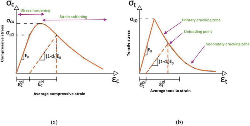
Figure 5 Dependence of stress on total strain for: (a) compression and (b) tension [25].
The material properties for the stones and mortar used for this investigation are presented in Table 1.
Table 1 Mechanical properties of the masonry unit [26]
| Plasticity Parameter | Value |
| Dilation angle | 30 |
| Eccentricity parameter | 0.1 |
| Bi- and unidirectional compressive strength ratio | 1.16 |
| Stress ratio in tensile meridian | 0.67 |
| Viscosity parameter | 0.001 |
The material properties for masonry unit that was adopted for this study included the modulus of Elasticity of 15500 Mpa, Poisson’s ratio of 0.15, tensile strength of 1.05 Mpa and the compressive strength of 10.5 Mpa.
By adopting the constitutive descriptions provided above, the basic failure modes that are shown in Figure 6 can be taken into account by the proposed finite element model, as also depicted in [12].
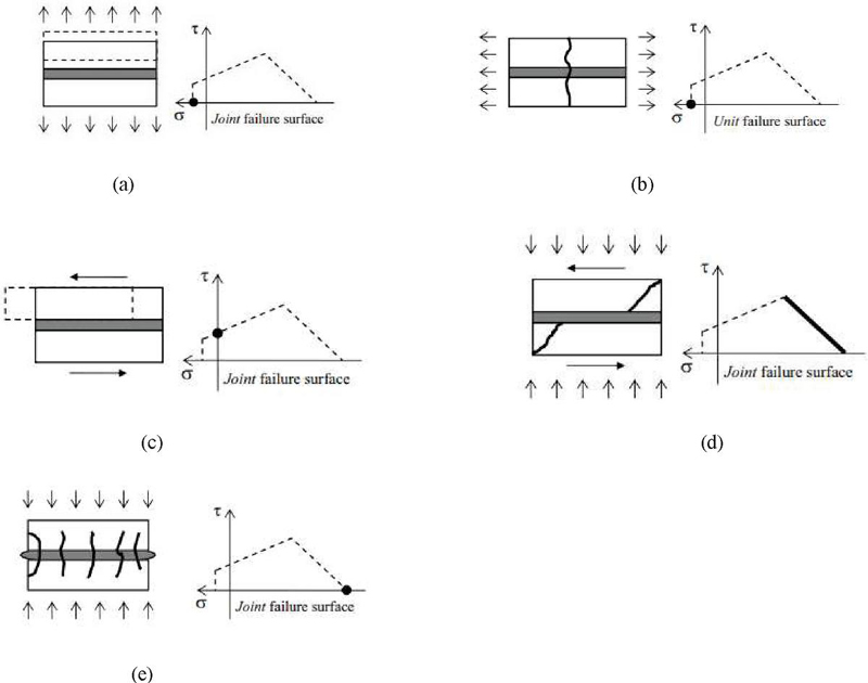
Figure 6 Basic failure modes in masonry as part of the modelling strategy. (a) Joint tensile cracking; (b) Cracking on unit in direct tension (c) Joint slip failure; (d) Unit diagonal tension cracking; (e) Masonry crushing [27].
To capture the failure response of the walls shown in Figure 2, non-linear finite element models were developed using commercial finite element software (ABAQUS). At the top of the wall, a rigid (concrete) beam was attached. The different material properties used to model the masonry are listed in Table 1.
The masonry walls were meshed using 8-noded, hexahedral, linear brick finite elements. The mesh size used for both brick and concrete beam was 30 mm as shown in Figure 7(d). An explicit dynamic analysis was used to capture the effect of blast loading. Within this consideration, quite small time steps are considered, which makes the explicit dynamic simulation appropriate for blast actions with pretty small duration.
To simulate the blast load, two reference points were assigned depending on standoff distance from the site of reaction. The surface blast load was then created using the CONWEP model as defined in ABAQUS. This model has been implemented to simulate the air blast load, and it assumes a spherical charge detonated in free air. For the out-of-plane response, the wall was fixed on all four sides while in the in-plane investigation the wall was fixed only at the base. The numerical analysis was carried out using an explosive weight of 50 kg TNT at 20 m. Figure 7 shows the wall patterns used in this study.
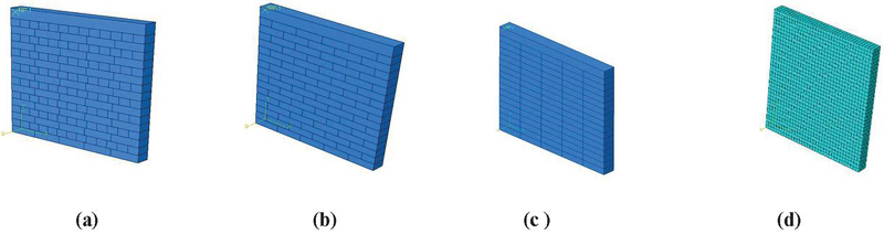
Figure 7 Numerical Model of Masonry wall in ABAQUS: (a) English bond; (b) Stretcher bond; (c) Stack bond; (d) mesh of the model.
The brick sizes that were used to develop the model were standard concrete brick size of 222 mm (L) 106 mm (W) 73 mm (H). The modelled wall is 1110 mm wide and 1268 mm high including a beam of 100 mm deep which is considered at the top of the wall.
The proposed model is validated using published literature for both in-plane and out-plane failure. As part of the novelty of this study, comparison of the response obtained from various brick bonding types will be made with reference to out-of-plane actions due to blast loading. The proposed model is validated using published results by other researchers on numerical and experimental studies. In addition, a mesh convergence investigation is conducted.
The verification of the proposed model was implemented using the failure mode from the experiment conducted by Vermeltfoort and Raijmakers [28]. In the experiment, a wall size of 990 mm 1000 mm, with 18 layers of solid clay bricks (dimensions 204 98 50 mm) has been investigated. Furthermore, the tests considered vertical pre-compression pressure and a horizontal displacement loading as shown in Figure 8.
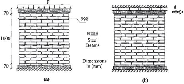
Figure 8 Loading of the specimen: (a) vertical loading; (b) horizontal loading [28].
In the results presented in Figure 9(a), cracking at the bottom and top of the masonry wall indicated the beginning of the wall’s failure mechanism. Following the appearance of a diagonal shear fracture and an increase in lateral displacement, the structure collapsed. The failure mechanism is shown in Figure 9 which is compared with the failure pattern obtained from the numerical model developed in this study.
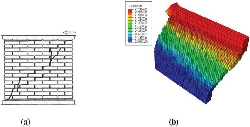
Figure 9 Comparison of failure modes of a masonry wall: (a) Experimental failure pattern; (b) failure pattern from numerical model (scale factor 20).
As seen in Figure 9, the damage initiation and formation obtained from the numerical model is in close agreement with experimental model which there validates the model. Figure 10 shows the damage patterns on the building caused by in-plane loading, noting that the direction of cracking follows that of the experimental model and numerical model.
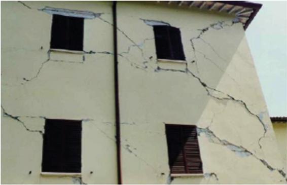
Figure 10 Building damage due to in-plane loading.
A running bond masonry wall subjected to a distributed blast pressure was investigated by Milani et al. [29], as shown in Figure 11(a). A 3-side constraint approach was used with the top position taken as free. Bricks in the 3D model used for validation were considered to have a stiff, infinite resistant behaviour, while joints were subjected to the same Mohr-Coulomb failure criterion with the same tensile strength and friction angle as joints in the homogenised method.
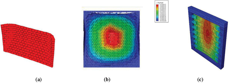
Figure 11 (a) out-of-plane response due to blast loading [28]; (b) out of plane response due to blast by [29]; (c) proposed model.
Figure 11(b) depicts the deformation shape of a masonry wall subjected to 58.8 kg TNT at a standoff distance of 5.5 m from a study conducted by Zhang et al. [30]. This study is comparable to the results obtained in this work as can be seen in Figure 11(c), where there is excessive deflection at the centre portion of the wall. Figure 12 shows the wall that was studied by Hao [31] who considered a 2880 mm wide 2820 mm high wall which was fixed on all four sides.
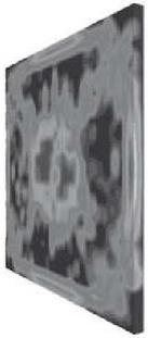
Figure 12 Simulation of the response to a surface blast due to a TNT explosive weight W 200 kg, located at 41 m from blasting source [31].
At the distance of 41 m, the study presented in [31] highlighted that the wall undergoes extensive damage but does not collapse. As expected, this study further highlighted that the increase in blast weight at the standoff distance of 41 m leads to much higher deflection. The above comparison of the failure mode/pattern validates the proposed model as the wall’s failure patterns are all in good agreement.
Next, a mesh convergence analysis on the finite element model proposed in this article is conducted. A model with the stretcher bond wall is generated, and different values of the mesh size are chosen. A comparison of the output (deflection at the centre of the wall) for different mesh sizes was conducted and the optimal size with satisfactory accuracy and computational efficiency was selected. The results of the mesh convergence test are shown in Figure 13 and Table 2. The corresponding simulations were conducted using a blast load of 30 Kg TNT at a standoff distance of 20 m.
Table 2 Mesh convergence study
| Element Size (mm) | Element Count | Deflection (m) |
| 100 | 171 | 8.53E-05 |
| 80 | 241 | 9.29E-05 |
| 50 | 728 | 1.47E-04 |
| 25 | 9248 | 1.18E-04 |
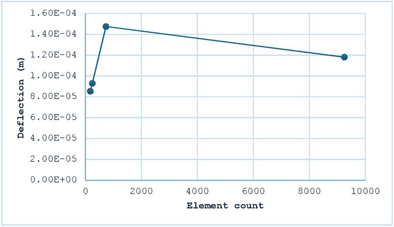
Figure 13 Correlation between mesh size and deflection value at the centre of the wall for a blast load of 30 Kg TNT at a standoff distance of 20 m.
Based on the above investigation of the effect of mesh size, a three-dimensional, eight-node linear brick elements are used, with the element side equal to 30 mm. It is noted that according to the diagram shown in Figure 13, a further reduction of the mesh size was found to be computational expensive and not yielding significantly different results.
The numerical analysis was performed on the wall with the pre-compression load of 0.25 Mpa and horizontal displacement of 20 mm that was applied on the concrete beam. The results for the three brick patterns are discussed below.
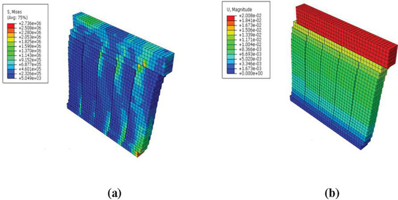
Figure 14 (a) In-plane maximum Von-Mises stresses (S, Mises); (b) In-plane deflection of stack bond wall.
The above figures show the opening of joints in the vertical direction. The non-linear behaviour of the stack bond wall is observed by initiation of cracks from the bottom and widen towards the upper part of the wall.
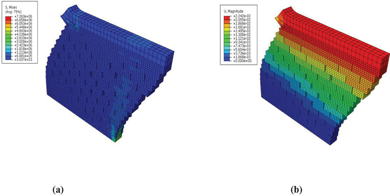
Figure 15 (a) In-plane maximum Von-Mises stresses (S, Mises); (b) In-plane deflection of stretcher bond wall (scale factor 20).
When compared with the stack bond, the stretcher bond wall has less deflection value. This brick pattern shows the diagonal cracking which is one of the expected modes of failure for walls that are subjected to in-plane loading. The tensile cracking leads to the diagonal stair-case crack.
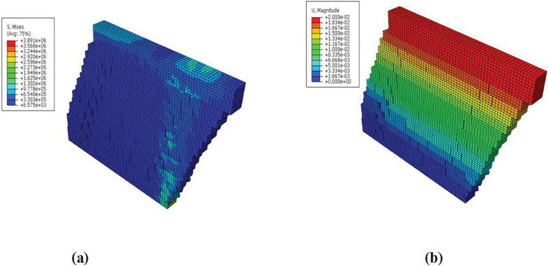
Figure 16 (a) In-plane maximum Von-Mises stresses (S, Mises); (b) In-plane deflection of english bond wall (scale factor 20).
The above results showed some similarity in terms of the mode of failure. Diagonal cracking in a form of stair-case crack shape was observed on the English bond and Stretcher Bond. On the other hand, the stacker bond depicted de-attachment of joints in the vertical direction. All three walls depicted higher concentration of von-Mises stresses at the bottom corner of the wall. The comparison of wall’s resistance is summarised on the graph below.
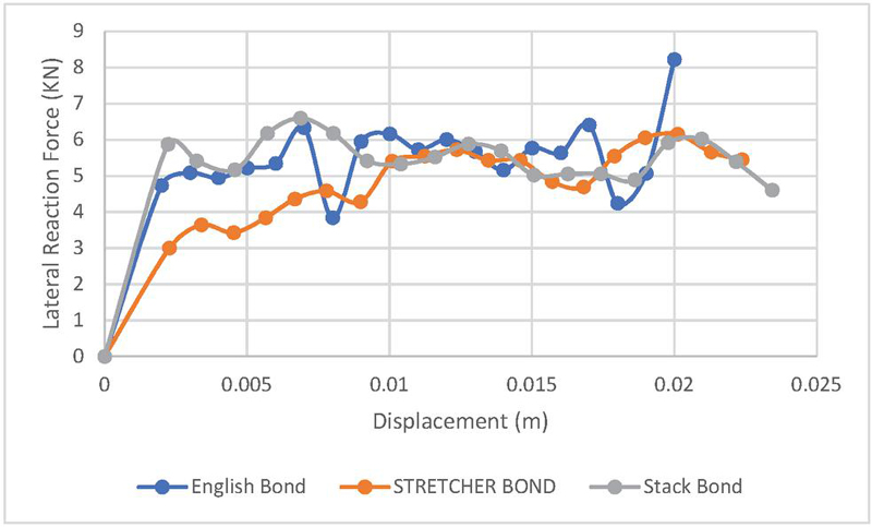
Figure 17 Comparison of resistance of wall against lateral displacement loading.
From Figure 17, it can be observed that the English bond produced higher resisting forces when compared with the other two walls, mainly at the level of maximum displacements.
This section discusses the results from the application of blast loading considering an explosive weight of 50 kg TNT at a standoff distance of 20 m. The results from the three different walls are herein compared. The behaviour of the masonry wall in terms of Von-Mises stresses, defection concrete damage (tension and compression) is discussed in this section. The concrete damage plasticity model as discussed in Section 3, was able to produce the compression and tensile damage of the wall. Relevant results are presented in Figures 18–20.
The English bond experiences minimal compression damage. Tension damage is observed under this bond type at the boundary positions and on some of the middle brick units. The deflection of the wall as expected is higher at the center of the wall.
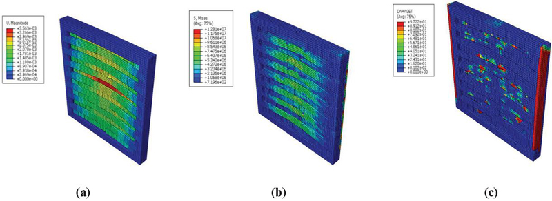
Figure 18 (a) Displacement of the English-bond wall at the end of the simulation (m), (b) Maximum Von-Mises stresses (S, Mises), (c) tensile damage variable distribution. (Scale factor 30).
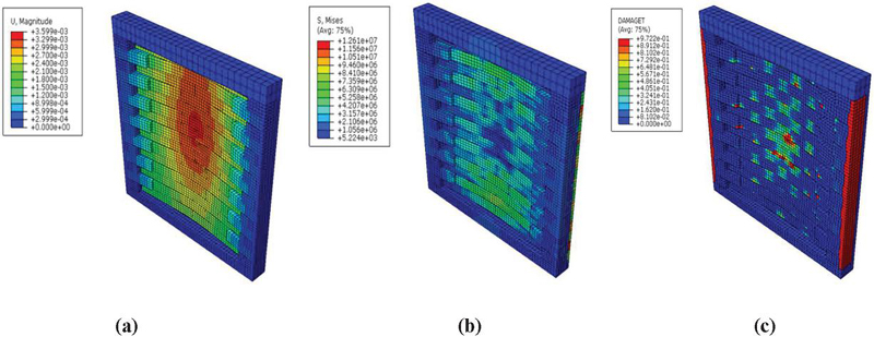
Figure 19 (a) Displacement of the Stretcher Bond wall at the end of the simulation (m), (b) Maximum Von-Mises stresses (S, Mises), (c) tensile damage variable distribution. (Scale factor 30).
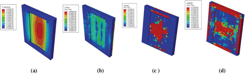
Figure 20 (a) Displacement of the Stack Bond wall at the end of the simulation (m), (b) Maximum Von-Mises stresses (S, Mises) (c) compressive damage variable and (d) Maximum tension damage. (Scale factor 30).
From an architectural point of view, stack bond can have a beautiful appearance, but it is typically seen to have a weaker binding pattern than other widely used bonds like English bond and stretcher bond. As can be seen in Figure 20(a), the first column/courses of bricks separate from the neighboring bricks and it is worth noting that the vertical joints are easily prone to separation when subjected to lateral stresses, such as blast loads, which compromises structural integrity. Vertical cracking also happens. Stack bond masonry walls are vulnerable to vertical cracking at the vertical mortar joints because they lack horizontal support.
From the above results, it can be highlighted that the masonry head joint played a role in the out of plane response. It can be concluded that the English bond and stretcher bond have similar failure margins. The de-attachment of bricks in the vertical direction in the stack bond displayed a failure pattern that would be expected when there is a vertical expansion joint on the wall. Additionally, the location and magnitude of maximum von Mises stress amongst the three walls were within similar ranges and with all walls depicting maximum out of plane in the middle section of the wall.
From Figure 20, it can be seen that the tension and compression damage for stack bond is much higher than the other two walls (stretcher bond and English bond). The displacement observed on the stack bond proves the importance of brick reinforcement in masonry wall.
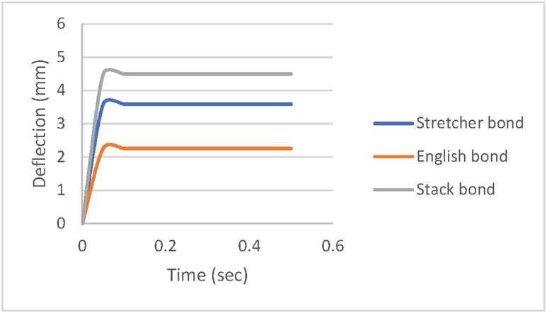
Figure 21 Deflection vs time for blast weight of 50 kg TNT.
The deflection of the three walls is summarized in Figure 21, and as discussed above, the de-attachment of bricks (second column) from the fixed sides initiated a much higher relative displacement on the stack bond when compared with the other two walls.
The comparison below shows that the stack bond has slightly higher out of plane displacement when compared to the other two bonding patterns. In practice, the bedding reinforcement in the case of stack bond is crucial when used a structural/load bearing wall. The deformation due to blast load occurs within a short duration of time as can be observed in Figure 21.
This study concluded that there is a slight difference in the peak displacement at the center of the wall for the English and stretcher bond. Under these two bonding patterns, when the blast load is lower it results in a lower wall center displacement. The stack bond on the under hand displayed higher deflection values under both in plane and out-of-plane loading. The research results in this paper highlighted that the stack bond arrangement has the vertical joints are easily prone to separation when subjected to lateral stresses, such as blast loads, which compromises structural integrity. Also, Stack bond masonry walls are susceptible to vertical cracking at the vertical mortar joints because they lack horizontal support. The different brick patterns play a role in the blast resistance of the wall. This research work was able to highlight the importance of understanding the effect of different bonding patterns for structural walls.
Conceptualization, S.G.T.; methodology, S.G.T.; formal analysis, S.G.T.; investigation, S.G.T. and G.A.D.; resources, G.A.D.; data curation, S.G.T..; writing – original draft preparation, S.G.T.; writing – review and editing, S.G.T., G.A.D., S.M.M and G.E.S.; visualization, S.G.T.; supervision, G.A.D. and G.E.S..; project administration, G.A.D. All authors have read and agreed to the published version of the manuscript.”
This research received no external funding.
Not applicable.
The authors declare no conflict of interest.
[1] Debnath, P.; Dutta S.C.; Mandal, P. Lateral behaviour of masonry walls with different types of brick bonds, aspect ratio and strengthening measures by polypropylene bands and wire mesh, Structures Volume 49, March 2023, Pages 623–639, 2023, https://doi.org/10.1016/j.istruc.2023.01.155.
[2] Shrestha, J.K.; Pradhan, S.; Gautam, D. In-plane behaviour of various brick bonds in masonry walls, Innovative Infrastructure Solutions (2020) 5:58, 2020, https://doi.org/10.1007/s41062-020-00306-x.
[3] Bacigalupo, A.; Cavicchi, A.; Gambarotta, L. A simplified evaluation of the influence of the bond pattern on the brickwork limit strength, Advanced Materials Research Vols. 368–373, 2012, pp. 3495–3508, Trans Tech Publications, Switzerland doi:10.4028/www.scientific.net/AMR.368-373.3495 available at www.scientific.net, date accessed May 2023.
[4] Shah, S.A.R.; Arshad, H.; Farhan, M.; Raza, S.S.; Khan, M.M.; Imtiaz, S.; Gullnaz, S.; Qurashi, M.A.; Wassem, M. Sustainable Brick Masonry Bond Design and Analysis: An Application of a Decision-Making Technique, Appl. Sci. 2019, 9, 4313; doi:10.3390/app9204313.
[5] Thango, S.G.; Stavroulakis, G.E.; Drosopoulos, G.A. Investigation of the Failure Response of Masonry Walls Subjected to Blast Loading Using Nonlinear Finite Element Analysis. Computation 2023, 11, 165. https://doi.org/10.3390/computation11080165.
[6] Elmenshawi, A.; Duchesne, D.; Paquette, J.; Mufti, A.; Jaeger, L.; Shrive, N. Elastic moduli of stone masonry based on static and dynamic tests. 2011. Paper presented at the 11th NAMC, Minneapolis, USA.
[7] D’Altri, A.M.; Miranda, S.; Castellazzi, G.; Sarhosis, V.A 3D Detailed Micro-Modelling Approach for the In-Plane and Out-Of-Plane Analysis of Masonry Structures, Computers & Structures. 2018, 206: 18–30. https://doi.org/10.1016/j.compstruc.2018.06.007.
[8] Pasquantonio, R. D.; Parsekian, A.; Fonsecan, S; Shrive, G. Experimental and numerical characterization of the interface between concrete masonry block and mortar. 13(3): 2020, 578–592. https://doi.org/10.1590/S1983-41952020000300008.
[9] Stankowski, T.; Runesson, K.; Sture, S. Fracture and Slip of Interfaces in Cementitious Composites Characteristics. 1993, 119(2): 292–314. https://doi.org/10.1061/(ASCE)0733-9399(1993)119:2(292).
[10] Weyler, R.; Oliver, J.; Sain, T; Cante, J. On the Contact Domain Method: A Comparison of Penalty and Lagrange Multiplier Implementations, 2012, Computer Methods in Applied Mechanics and Engineering, vol. 205–208, p. 68–82.
[11] Miranda Dias, J. L. Cracking due to shear in masonry mortar joints and around the interface between masonry walls and reinforced concrete beams. 2007, In Construction and Building Materials (Vol. 21, Issue 2, pp. 446–457). Elsevier BV. https://doi.org/10.1016/j.conbuildmat.2005.07.016.
[12] Ngo, T.; Mendis, P.; Gupta, A.; Ramsay, J. Blast loading and blast effects on structures, An overview. Electron J Struct Eng, 7, 76–91. 2007.
[13] Unified Facilities Criteria “UFC 3-340-02 Structures to Resist the Effects of Accidental Explosions”, U.S. Army Corps of Engineers, Naval Facilities Engineering Command, Air Force Civil Engineer Support Agency. 2008, available online https://www.wbdg.org/ffc/dod/unified-facilities-criteria-ufc/ufc-3-340-02, date accessed 01 May 2023.
[14] Lourenço, P.B Computational strategies for masonry Structures. 1996, Doctoral thesis, Delft University of Technology, Delft University Press.
[15] Lourenço, P. B. Computations on historic masonry structures. Progress in Structural Engineering and Materials, 2002. 4, 301–319.
[16] Lourenço.; Rots, J.G.; Blaauwendraad, J. Two Approaches for the Analysis of Masonry Structures: Micro and Macro-Modelling, Heron. 1995, 40(4): 313–338. ISSN 0046-7316.
[17] Braimah, B, Blast load effects on historic masonry buildings, Technical report, Infrastructure Protection and International Security Department of Civil and Environmental Engineering Carleton University, 2013.
[18] Kömürcü, S.; Gedikli, A. Macro and Micro Modelling of the Unreinforced Masonry Shear Walls, European Journal of Engineering and Natural Sciences. 2019, 3(2): 116–123. https://dergipark.org.tr/en/pub/ejens/issue/49410/369461.
[19] Drosopoulos, G.A.; Stavroulakis, G.E. A computational homogenization approach for the study of localization of masonry structures using the XFEM. Arch Appl Mech Vol. 88, 2018, pp. 2135–2152. https://doi.org/10.1007/s00419-018-1440-4.
[20] Daniel, J.; Dubey, R. Finite Element Simulation of Earthquake Resistant Brick Masonry Building Under Shock Loading. Adv. Struct. Eng. 2014, 81, 1027–1038. https://doi.org/10.12989/csm.2015.4.1.019.
[21] Lubliner, J.; Oliver, J.; Oller, S.; Oñate, E. A plastic-damage model for concrete”, International Journal of Solids and Structures. 1989, 25: 299–329. https://doi.org/10.1016/0020-7683(89)90050-4.
[22] Lee, J.; Fenves, G.L. Plastic-Damage Model for Cyclic Loading of Concrete Structures. Journal of Engineering Mechanics, 1998, 124(8): 892–900, DOI: 1008 https://doi.org/10.1061/(ASCE)0733-9399(1998)124:8(892).
[23] Lee, J. Theory and implementation of plastic-damage model for concrete structures under cyclic and dynamic loading. 1996, PhD Dissertation. Berkeley, California, USA: University of California.
[24] Alhadid, M.M.A.; Soliman, A.M.; Nehdi, M.L.; Youssef, M.A. Critical overview of blast resistance of different concrete types, Magazine of Concrete Research, 2013, 65(1), 1–10 http://dx.doi.org/10.1680/macr.13.00096.
[25] ABAQUS v. 6.14.2 User’s Manual. Available online: http://130.149.89.49:2080/v2016/index.html (accessed on 7 May 2023).
[26] Iuorio, O.; Dauda, J.A. Retrofitting Masonry Walls against Out-Of-Plane Loading with Timber Based Panels, Appl. Sci. 2021, 11, 5443. https://doi.org/10.3390/app11125443
[27] Chaimoon, K, Numerical simulation of fracture in unreinforced masonry, 2007, PhD thesis, School of Civil and Environmental Engineering, The University of New South Wales, Syndey, Australia, https://doi.org/10.26190/unsworks/17488.
[28] Vermeltfoort, A. T., Raijmakers, T., and Janssen, H. J. M, Shear tests on masonry walls, 6th North American Masonry Conference, 6–9 June 1993, Philadelphia, Pennsylvania, USA, 1993 (pp. 1183–1193). Technomic Publ. Co.
[29] Milani, G.; Lourenço, P.B.; Tralli, A, homogenized rigid-plastic model for masonry walls subjected to impact, Int. J. Sol. Struct. Vol. 46(22–23), 2009, pp. 4133–4149.
[30] Zhang, Y.; Hu, J.; Zhao, W.; Hu, F.; Yu, X. Numerical Study on the Dynamic Behaviours of Masonry Wall under Far-Range Explosions. Buildings, 2023, 13, 443. https://doi.org/10.3390/buildings13020443.
[31] Hao, D. Numerical Modelling of Masonry Wall Response to Blast Loads, Australian Journal of Structural Engineering. 2009, 10(1):37–52. https://doi:10.1080/13287982.2009.1146503.

Sipho Gcinangaye Thango is currently a practising Structural Engineer with vast experience in the analysis and modelling of structures. He holds a PhD degree from University of KwaZulu Natal. He received a master’s degree from the University of Witwatersrand in 2018. He is currently part of the UKZN research group (Structural Engineering & Computational Group).

Siphesihle Mpho Motsa is currently a practising Structural Engineer with vast experience in the analysis and modelling of masonry structures. He holds a PhD degree from University of KwaZulu Natal. He has been author of publications in international journals and conferences proceedings. Dr. Motsa finished his undergraduate studies in Civil Engineering, UKZN, in 2017. In 2018 he completed his MSc studies on the concept of non-linear finite element analysis for masonry structures. He is currently part of the UKZN research group (Structural Engineering & Computational Group).

George E. Stavroulakis obtained his PhD from Aristotle University of Thessaloniki in 1991. His research activities are focused on the development of theory, algorithms, and software for the solution of modern computational mechanics and optimization problems. The development of scientific software deals with topics of structural analysis, computational mechanics, and optimization as well as the support of relevant research and development activities, in close cooperation with various partners. Dr. Stavroulakis is a Professor at Technical University of Crete, Greece and leads the Computational Mechanics and Optimization institute (COMECO).

Georgios A. Drosopoulos completed the post-doctoral research programme in Leibniz University of Hannover, Germany and Technical University of Crete, Greece, Prof. Drosopoulos was appointed as a Senior Lecturer in Civil Engineering at UKZN (July 2016). In November 2019, he was promoted to Associate Professor. From 2020–2024 he worked as Lecturer in University of Central Lancashire, UK. Since 2024 he works as Assistant Professor in the Department of Civil Engineering, International Hellenic University in Greece.
His research focuses on problems related to data-driven analysis for structural mechanics, contact mechanics, multi-scale homogenization for the investigation of the microscopic level of composite materials, non-linear finite element analysis of masonry structures, auxetic materials, topology optimization and homogenization, non-linear finite element analysis for steel structures. Recently his research focuses on the structural evaluation and optimization of Graphene and Carbon-Nanotube reinforced composite materials.
European Journal of Computational Mechanics, Vol. 34_1, 29–54.
doi: 10.13052/ejcm2642-2085.3412
© 2025 River Publishers