Mechanical Behavior Analysis of High Strength Concrete Beams in Architectural Design: Simplified Calculation Method of Flexural and Shear Bearing Capacity
Yu Peng1 and Shuang Zhou2,*
1School of Arts Design, Wuchang Institute of Technology; Wuhan, Hubei, 430065 China
2School of Art, Hubei University; Wuhan, Hubei, 430062 China
E-mail: 20180118@hubu.edu.cn
*Corresponding Author
Received 07 January 2024; Accepted 30 January 2024; Publication 24 February 2024
Abstract
This study advances the use of high-strength concrete beams in structural engineering by analyzing their flexural behavior. Utilizing a combination of theoretical and empirical methods, the research develops equations for calculating the cracking moment and ultimate load capacity of these beams. Key findings include a shear-bearing capacity calculation model, validated by experimental data, with discrepancies in cracking moment and ultimate load-bearing capacity formulas being only 6.16% and 1.53% respectively. These results offer significant insights for the design and analysis of high-strength concrete beams in architectural engineering, demonstrating high accuracy and stability.
Keywords: Architectural design, high-strength concrete, cracking moment, ultimate bearing capacity, shear-bearing capacity.
1 Introduction
High-strength concrete, known for its superior compressive strength, enhanced deformation resistance, high density, and reduced porosity, is widely used in large-scale structures such as skyscrapers, expansive bridges, and unique constructions [1–3]. Recent advancements have seen the integration of fiber materials into high-strength concrete, significantly improving its tensile strength, compressive strength, elasticity modulus, and durability, while maintaining excellent flowability [4–6]. This is a notable shift from traditional concrete practices and highlights the material’s evolving role in modern engineering designs [7].
Recent studies further expand our understanding of high-strength concrete. For example, research by Yang et al. [8] examined 14 high-strength concrete beams, uncovering that casting methods greatly impact their bending load capacity, even with identical cross-sections and reinforcement ratios. Additionally, Fu Qiang et al. [9] investigations on the effects of different longitudinal reinforcement ratios reveal that increased reinforcement in the compressed zone can mitigate crack formation and reduce deflection under load, an important consideration for structural design.
While much of the existing literature focuses on reinforced high-strength concrete beams, exploring the properties of unreinforced variants is crucial for a comprehensive understanding of the material’s inherent bending characteristics. These investigations are pivotal for the practical application and advancement of high-strength concrete beams, despite current research in this area being relatively limited [10–12].
This paper, therefore, undertakes a study on the bending bearing performance of concrete beams, employing both theoretical analysis and experimental validation. It is anchored on the flat section assumption and the compressive stress-strain relationship equation for high-strength concrete beams. The research utilizes ultimate bearing capacity calculation values from DBJ 43/T 325—2017 “Technical Specification for Reactive Powder Concrete Structures” and T/CCPA 35—2022 “Design Specification for Ultra-High Performance Concrete Structures”. The study successfully deduces formulas for the cracking moment and ultimate bearing capacity of high-strength concrete beams. Moreover, drawing on the mechanical flat push theory, it formulates a shear-bearing capacity calculation model for high-strength concrete beams, offering valuable insights for the structural design of such beams.
2 Calculation of High-Strength Concrete Beam Load-Bearing Capacity in Architectural Designs
2.1 Basic Assumptions
Considering the tensile action in the tensile zone of high-strength concrete beams, the load-bearing capacity calculation of the normal section of high-strength concrete beams differs from that of ordinary reinforced concrete components [13–15]. To analyze the entire stress process of the normal section of high-strength concrete beams, the following two assumptions need to be established:
(1) Plane Section Assumption During the entire stress process of the normal section of high-strength concrete beams, the mid-span section approximately remains planar. Therefore, adopting the plane section assumption facilitates the establishment of the computational model.
(2) Stress-Strain Relationship of High-Strength Concrete Beams Under Compression The stress-strain relationship equation for high-strength concrete beams under compression is as shown in Equation (1):
| (1) |
In the formula: represents the stress of the concrete at a strain of , in MPa; fc is the axial compressive strength of the concrete, in MPa; define x as , where 0 is the peak compressive strain of the concrete, in microstrain ().
2.2 Beam Design
For ease of calculation and analysis, the design of the plain high-strength concrete beam adopts a rectangular cross-section, with a simple support structure, a length of 1.2 m, a width of 0.15 m, and a height of 0.3 m. The beam overhangs 15 cm on each side of the support, making the calculated span 0.9 m. The axial compressive strength of the high-strength concrete beam is taken as 23 MPa, and the axial tensile strength as 10.55 MPa.
2.3 Calculation of Cracking Moment
To simplify the calculation, the same method as for ordinary reinforced concrete components is adopted, equating the longitudinal reinforcement steel to an equivalent area of high-strength concrete beam with the same modulus [16–18]. In this case, the high-strength concrete beam can be considered as a homogeneous elastic material.
Introducing the plastic influence coefficient of the section resistance moment , and using the principles of material mechanics to establish a crack resistance formula, the Mcr calculation formula is as follows:
| (2) |
The equation involves , which represents the cracking moment for the plain high-strength concrete beam, measured in kNm; , the coefficient impacting the plastic behavior of the beam’s section resistance moment; , denoting the peak tensile stress of the beam in MPa; and , signifying the section’s elastic resistance moment to the tensile edge, expressed in cubic meters.
For this high-strength concrete beam, which is not reinforced, the converted cross-sectional area is:
| (3) |
The distance from the centroid of the section to the edge of the compression zone is:
| (4) |
The moment of inertia of the section about the centroidal axis is:
| (5) |
The elastic resistance moment of the section is:
| (6) |
The plastic influence coefficient of the section resistance moment is:
| (7) | ||
| (8) | ||
| (9) |
The formula includes: b, the width of the high-strength concrete beam in meters; h, the beam’s height in meters; Ws, the beam section’s elastic resistance moment considering plastic deformation in the tension zone, expressed in cubic meters; , the height of the compressed zone in the beam, in meters; , the initial cracking tensile strain of the beam in microstrain (); , the beam’s modulus of elasticity in GPa; and ft, its tensile strength in MPa. Due to the unavailability of experimental data for , an empirical formula is employed to compute the section resistance moment coefficient. Referring to Literature [14], for high-strength concrete beams with a rectangular section and about 100 MPa compressive strength, the formula for calculating the resistance moment influence coefficient relative to the reinforcement ratio is proposed:
| (10) |
Since the high-strength concrete beam is unreinforced, then:
| (11) |
In addition to the reinforcement ratio, the plastic influence coefficient is influenced by various factors such as the section’s height and shape, the type of steel fiber used, and the fiber volume fraction. The formula (12) is employed to calculate the plastic influence coefficient of the section resistance moment when there is a variation in the section height.
| (12) |
Combining formulas (2), (6), and (12), the calculated cracking moment is 28.72 kNm.
2.4 Calculation of Ultimate Load-Bearing Capacity
When calculating the bending load-bearing capacity of the normal section of high-strength concrete beams, for simplification, the same method as ordinary reinforced concrete components is adopted, treating the stress distribution of the high-strength concrete beam as an equivalent rectangular stress block [18–20].
(1) Simplification of Stress in the Compression Zone The resultant force of compressive stress in the concrete compression zone, Fc, is:
| (13) |
The distance from the resultant compressive force Fc to the neutral axis:
| (14) |
The compressive strain of concrete at a distance y from the neutral axis:
| (15) |
The variation of the resultant compressive force Fc:
| (16) |
The variation of the distance from the resultant force Fc to the neutral axis:
| (17) |
In the formula: is the ultimate compressive strain of concrete, in microstrain (); is the area enclosed by the stress-strain curve in the compressed zone of high-strength concrete beam, in MPa; is the distance from the centroid of the area to the origin O, in microstrain (). Then:
| (18) | ||
| (19) |
Based on the compressive constitutive relationship Equation (1) of high-strength concrete beam:
| (20) | ||
| (21) |
Introducing parameters , satisfying:
| (22) |
The bending moment carried by the concrete in the compression zone:
| (23) |
In the formula: fc is the compressive strength of the high-strength concrete beam, in MPa; x is the equivalent height of the stress in the compression zone, in m.
Where:
| (24) |
Introducing parameter , satisfying:
| (25) |
Then:
| (26) |
Solving gives , , thus the equivalent rectangular stress height of the compressed zone of the high-strength concrete beam is 0.81, with a stress magnitude of 0.89fc.
(2) Simplification of Stress in the Tension Zone Height of the tension zone:
| (27) |
From the balance condition:
| (28) | |
| (29) |
When the high-strength concrete beam fails, the ultimate bending moment equals the cracking moment, i.e., Mu Mcr. Combining formulas (28) and (29), the expression for the equivalent height x of the compression zone is obtained:
| (30) |
Where:
| (31) |
Therefore, the equivalent height of the compression zone x 11.56 mm.
Substituting into formula (28), the equivalent coefficient k of the tension zone is 0.42. Considering a safety reserve, the equivalent coefficient k of the tension zone is taken as 0.35. Thus, the formula for calculating the ultimate load-bearing capacity of the section under bending is:
| (32) |
Substituting the data, the ultimate load-bearing capacity Mu 33.24 kNm.
2.5 Calculation of Ultimate Load-Bearing Capacity According to DBJ 43/T 325—2017
In DBJ 43/T 325—2017, the uniaxial compressive stress-strain relationship for high-strength concrete beams is given as:
| (33) |
The standard value of axial compressive strength of high-strength concrete beams, fcu, is 127.23 MPa.
The standard value of the cube compressive strength, fcu, k, is 1.45 fcu 184.48 MPa. Where:
| (34) | ||
| (35) | ||
| (36) | ||
| (37) | ||
| (38) |
From formulas (25) and (26), and . Relative limit of the height of the compression zone:
| (39) |
The calculation of the bending load-bearing capacity of the normal section of the bending member should comply with the following regulations:
| (40) |
The height x of the concrete compression zone is determined by the following formula:
| (41) |
Substituting the data, the equivalent height of the compression zone x is obtained as 7.22 mm.
The height of the concrete compression zone should also comply with the following condition:
| (42) |
From formula (2.5), the ultimate load-bearing capacity Mu is obtained as 17.35 kNm.
2.6 Calculation of Ultimate Load-Bearing Capacity According to T/CCPA 35—2022
The bending load-bearing capacity of the normal section of a bending member is calculated using the following formula:
| (43) |
In the given formula: represents the coefficient influencing the equivalent stress value, applicable when the stress distribution in a high-strength concrete beam’s compressed zone under non-uniform loading approximates a rectangular shape, and is assumed to be 0.75. The symbol x denotes the height of this equivalent rectangular stress distribution in the beam’s compressed zone, measured in meters. The term k serves as the reduction coefficient for the equivalent stress in the beam’s tensile zone, set at 0.25. Finally, is defined as the ratio of the height x of the rectangular stress distribution in the beam’s compressed zone to the height of the neutral axis, and is valued at 0.75.
From formula (36), the relative limit height of the compression zone, , for the high-strength concrete beam component is obtained.
The height x of the concrete compression zone is determined by the following formula:
| (44) |
Substituting the data, the equivalent height of the compression zone x is obtained as 8.26 mm.
The height of the concrete compression zone should also comply with the following condition:
| (45) |
From formula (40), the ultimate load-bearing capacity Mu is obtained as 17.30 kNm. In summary, the cracking moment of the high-strength concrete beam is 28.72 kNm, and the ultimate load-bearing capacity is 33.24 kNm, while the ultimate load-bearing capacities calculated according to DBJ 43/T 325—2017 and T/CCPA 35—2022 are smaller, at 17.35 and 17.30 kNm, respectively.
3 Mechanical Equilibrium-Based Calculation Model for Shear Capacity of High-Strength Concrete Beams in Modern Architectural Design
3.1 Application of Mechanical Equilibrium Design Method in Architecture
When a beam component undergoes shear failure, several diagonal bending shear cracks typically form within its shear span region. Initially, these cracks appear vertically at the lower part of the beam and gradually extend upward at an angle, evolving into bending shear cracks. For ease of analysis and calculation, the shear cracks on the inclined section can be considered to develop linearly. Within the shear span of the beam component, the numerical relationship between the cracking load (Vcr) and the sliding strength (Vsl) is crucial in determining the component’s shear bearing capacity. For instance, in the diagonal crack plane AD as shown in Figure 1, if the cracking load Vcr-AD is less than the sliding strength Vsl-AD, then Vsl-AD becomes the decisive factor for the shear capacity of that plane. Conversely, on the crack plane AB, where the cracking load Vcr-AB exceeds the sliding strength Vsl-AB, it is Vcr-AB that predominantly dictates the shear bearing capacity of the inclined section AB.
Figure 1 Relationship between cracking load, sliding strength, and the critical angle of diagonal cracks.
Figure 2 Distribution of cracks.
Figure 2 illustrates the relationship between the cracking load (Vcr) and sliding strength (Vsl), and the critical angle of shear sliding failure surface diagonal cracks (p). When a component undergoes shear failure, for any specific angle of diagonal cracks, there exist corresponding values of Vcr and Vsl, along with their relative magnitude relationship. In the figure, as the crack angle increases, the cracking load Vcr gradually decreases and the sliding strength Vsl increases. Hence, there must exist a failure section within the shear span. In Figure 2, section AC, located between sections AB and AD, satisfies the condition where the cracking load Vcr equals the sliding strength Vsl. This equality determines the shear bearing capacity Vu of the beam component. For the diagonal crack section AC, this corresponds to the intersection point F in Figure 2 where Vcr equals Vsl. If the shear load at the critical angle of the shear failure surface causes a shear load equal to Vcr, leading to shear along the diagonal crack and resulting in a shear load Vu, then the shear bearing capacity Vu of the component equals the sliding strength Vsl. Based on this, by calculating the sliding bearing strength Vsl according to the critical angle of the diagonal cracks, the value of Vsl at the critical intersection point F can be obtained, thereby determining the shear bearing capacity Vu.
3.2 Derivation of Calculation Formula
Figure 3 presents the internal force dynamics in a stirrup-less concrete component’s shear inclined section. External forces, Va and Ma, influence the isolated section of the key diagonal crack AB. Shear forces arise along this diagonal segment to counter Va’s vertical load, while Ma’s bending moment induces a rotation for equilibrium. At this stage, the failure plane is hypothesized to shift from AB to A1B1, aligning with the neutral axis height d’s gradual adjustment for force balance. Above the neutral axis, the concrete is compressed, exhibiting diagonal cracks only in its tensile zone. This allows for a numerical force analysis in each part of this section under Ma and Va, including forces Pcc, Psc, Pct, and Pst.
Figure 3 Internal force along the critical failure inclined plane.
In Figure 3, the term denotes the relative height of the compression zone. Distances d and d measure from the top of the beam and the tensile reinforcement to the point where the resultant force of the compressed concrete acts, respectively. The angle represents the critical angle for the diagonal crack of the shear failure surface, while S indicates the shear force along this surface.
In concrete beams lacking stirrups, the development and width of diagonal cracks are less effectively constrained, primarily due to the absence of stirrups. This leads to a scenario where the shear resistance against sliding along these crack surfaces predominantly relies on the integrity of the uncracked concrete within the shear compression zone. The mechanisms of aggregate interlock across diagonal cracks and the dowel action of longitudinal reinforcement play only a minor role in enhancing the shear bearing capacity. Consequently, it is hypothesized that the primary source of shear bearing capacity emanates from the concrete situated in the compression zone above the neutral axis. This approach effectively disregards the contribution of concrete below this axis and considers the influence of as insubstantial. Additionally, the effect of compressive steel reinforcement above this zone on shear bearing capacity is deemed marginal and can be reasonably omitted.
In line with these assumptions, a detailed examination of the forces exerted on each segment along the critical diagonal crack shear plane is conducted, adhering to the principles of mechanical equilibrium. This analysis encompasses the assessment of both horizontal and vertical force equilibriums and includes the computation of a moment around point A. Such an approach facilitates the derivation of the following equations:
| (46) | |
| (47) | |
| (48) |
By combining equations (46) and (47), the resultant force of the concrete in the compression zone, , is obtained:
| (49) |
Combining equations (48) and (49), the second form of the expression for the compressive force in the concrete compression zone, , is derived:
| (50) |
Given that the resistance of the compression zone primarily contributes to the shear bearing capacity of the uncracked zone, it follows that in Figure 3, the pre-sliding sliding strength of this zone is a key determinant of the shear bearing capacity along the shear failure crack surface. Consequently, the sliding bearing capacity of the compression zone, denoted as Zcap, is represented by the product of the area of the inclined plane section above the neutral axis and the shear stress along the compression zone’s sliding surface. This is elaborated in Equation (50):
| (51) |
Furthermore, a strong linear relationship exists between the shear stress along the shear failure surface and the normal stress on the inclined section. Hence, it is posited that the shear stress along the sliding surface adheres to the relationship outlined in Equation (52). In this equation, the coefficients and are indicative of the shear friction characteristics prior to sliding:
| (52) |
Assuming that the compressive force in the compression zone is uniformly distributed, the normal stress can be determined as:
| (53) |
In this context, represents the normal force component of exerted on the inclined section, which hinders the sliding of the concrete in the compression zone. Concurrently, a portion of the sliding bearing capacity counters the shear force component along the inclined sliding surface, , thereby maintaining equilibrium in the isolated segment. As a result, the maximal shear force Smax present on the critical diagonal sliding surface equates to the discrepancy between and the tangential influence of the concrete compression force in the compression zone, as illustrated in the following expression:
| (54) |
At the onset of shear sliding failure in the component, the shear bearing capacity Vu is numerically equal to the maximum sliding bearing capacity :
| (55) |
By combining Equations (48), (51), (54), and (55), the maximum shear force on the critical failure inclined plane before shear sliding can be obtained, as shown in Equation (56):
| (56) |
Substituting Equations (52) and (53) into Equations (55) and (56), we get:
| (57) |
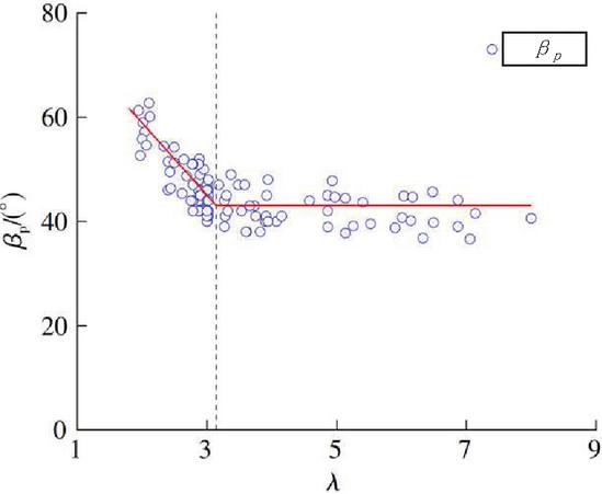
Figure 4 Derivation of in terms of shear-span ratio.
With the coefficient C defined as [, and substituting Equations (49), (50), and (55) into Equation (57), a second form of the calculation formula for shear bearing capacity can be derived.
| (58) |
3.3 Determination of Calculation Parameters
The correlation between the inclination angle p and the shear-span ratio, a key factor, is clearly depicted in Figure 4. The data trend in this figure is effectively simplified into a bilinear model to achieve optimal correlation. As indicated by the data, there is a shift in the linear trend at a shear-span ratio of 3.14. For beam components with a shear-span ratio below this value, the angle p of the critical diagonal crack incrementally rises as the shear-span ratio diminishes. Importantly, when the shear-span ratio approaches 0, p trends towards 90, indicative of a purely shear condition. The relationship between the inclination angle p and the shear-span ratio has been analyzed using Origin software for regression, resulting in the calculation formula presented in Equation (59):
| (59) |
Current research indicates that due to the low tensile strength of concrete, bending cracks appear earlier in the web of the beam under load. The initial bending cracks quickly extend towards the neutral axis position, then gradually stabilize. With continued loading, the range and width of the cracks increase, while the height change is relatively small. Thus, the relative height of the compressed zone of the beam component, , can be determined based on the strain-based assumption of plane sections and linear-elastic bending theory.
| (60) |
In the equation, n is the ratio of the elastic moduli of steel and concrete, .
| (61) |
Here, is the conversion coefficient for the relative height of the compressed zone in bending members.
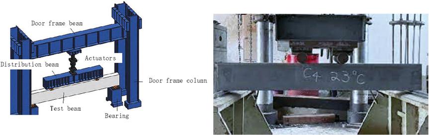
Figure 5 Experimental set-up.
4 Experimental Validation
To verify the accuracy of the proposed mechanical calculation model for high-strength concrete, a comprehensive experiment using a mixed loading method of force followed by displacement was conducted [21–23]. The experimental setup involved a two-point symmetrical vertical concentrated load applied to the specimen via a distributing beam, with the specimen being simply supported at both ends. This setup is depicted in Figure 5.
The experimental parameters were carefully selected to replicate realistic conditions. The load was applied gradually to monitor the beam’s behavior under increasing stress. Measurements included the displacement and deflection at the center of the beam’s bottom span, at the corresponding loading points on the beam’s bottom, and at the support positions. The concrete used was of grade C80, ensuring a high-strength quality for the experiment. To ensure accuracy, the concrete mix and curing process were strictly controlled, following industry standards. The load was applied incrementally, and data were recorded at each stage to track the progression of stress and deformation.
In the initial stages of loading deformation, the test beam displayed no notable deformations or surface cracks, indicating its operation within the elastic phase. With increasing load, fine cracks emerged at the center of the beam’s lower span, signifying a shift to the elastic-plastic stage as the concrete primarily absorbed the stress. When the load reached approximately 25% of the maximum bearing capacity, bending and diagonal cracks swiftly appeared in the shear span section. Progressing to 75% of the ultimate bearing capacity, these diagonal cracks expanded towards the supports, evolving into prominent main diagonal cracks [24–26]. At this juncture, the shear force shifted increasingly onto the longitudinal reinforcement, resulting in a marked increase in the number and width of cracks in the shear span section, as well as in deflection values. Continual loading up to the beam’s maximum bearing capacity was accompanied by distinct sounds, culminating in the main diagonal crack forming the final failure surface and localized concrete crushing, ultimately leading to the specimen’s failure [27, 28].
When compared to the data presented in Figure 6, it is noticeable that the growth patterns of the curves for the nine tested beams do not exhibit substantial differences. Initially, these curves demonstrate an almost linear ascending trend during the loading phase. However, upon the onset of diagonal cracking, there is a discernible reduction in the slope, with the most notable variances manifesting in the failure load values.
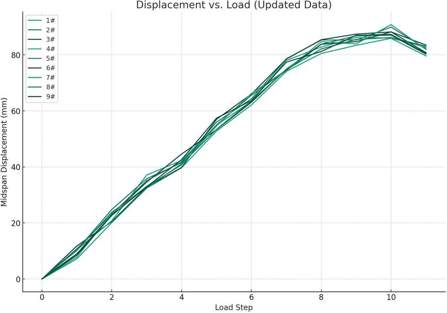
Figure 6 Displacement-load curve.
Employing the model previously elaborated upon, the shear bearing capacity of the beam specimens was calculated, and the results are comprehensively outlined in Table 1. This table indicates that the ratios of calculated to experimental values, derived using the mechanical equilibrium calculation model, ranged from 0.87 to 1.13. This range denotes a robust correlation with the experimental data and exhibits minimal deviation. Such an outcome underscores that the model introduced in this study accurately reflects the real shear bearing capacities of the 9 beams under examination, thereby providing significantly enhanced predictive accuracy and stability relative to other existing methodologies. Additionally, it is noteworthy that the discrepancy between the calculated and experimental results for both the cracking moment and ultimate load bearing capacity remained below 10%, which is considered to be within an acceptable error margin.
Table 1 Comparison of calculated and experimental values
| V/ | V/ | V/ | M | M | Deviation/ | M | M | Deviation/ | |
| Engineering | kN | kN | V | (kNm) | (kNm) | % | (kNm) | (kNm) | % |
| 1 | 31.27 | 27.28 | 0.87 | 28.72 | 26.95 | 6.16 | 33.24 | 33.70 | 1.38 |
| 2 | 41.01 | 36.85 | 0.90 | 32.42 | 33.12 | 2.16 | 37.74 | 38.02 | 0.74 |
| 3 | 40.22 | 38.59 | 0.96 | 31.41 | 32.47 | 3.38 | 36.51 | 36.42 | 0.25 |
| 4 | 42.27 | 38.91 | 0.92 | 33.84 | 34.91 | 3.16 | 38.95 | 38.47 | 1.23 |
| 5 | 42.91 | 42.90 | 1.00 | 33.65 | 34.86 | 3.60 | 39.24 | 39.84 | 1.53 |
| 6 | 45.01 | 39.94 | 0.89 | 37.28 | 38.51 | 3.30 | 42.85 | 41.97 | 2.06 |
| 7 | 54.13 | 58.94 | 1.09 | 49.47 | 49.98 | 1.04 | 52.13 | 52.02 | 0.21 |
| 8 | 62.22 | 62.19 | 1.00 | 42.51 | 44.32 | 4.26 | 57.45 | 57.06 | 0.68 |
| 9 | 68.40 | 77.31 | 1.13 | 45.68 | 46.14 | 1.01 | 59.68 | 59.79 | 0.18 |
| Note: V refers to the experimentally measured shear bearing capacity of the specimen; V is the shear bearing capacity value of the specimen calculated using the mechanical equilibrium-based model; V/V represents the ratio of the predicted shear bearing capacity from various concrete beam models to the experimentally measured value; M is the experimental value of the cracking moment; M is the calculated cracking moment using formulas; M is the experimental value of the ultimate moment; M is the calculated ultimate moment using formulas. | |||||||||
5 Conclusions
In this research, several key findings were made regarding the mechanical properties of high-strength concrete beams in architectural design:
In the initial design phase for calculating the cracking moment, the longitudinal force was equated to an area of high-strength concrete beams with the same elastic modulus, treating it as a homogeneous elastic material. Using empirical formulas, a formula for calculating the cracking moment of high-strength concrete beams was derived, which showed good agreement with experimental values. However, it’s important to note that this approach does not consider varying environmental factors such as temperature and humidity, which can affect the material properties.
In calculating the ultimate bearing capacity, the method used for ordinary reinforced concrete was adopted. The stress distribution of high-strength concrete beams was approximated as a rectangular stress block, leading to the derivation of a formula for the ultimate bearing capacity of high-strength concrete beams. While this formula showed good correlation with experimental values, especially for high-rise buildings and large-span structures facing heavy loads or complex stress conditions, the simplicity of the experimental beams may not fully capture the complexity of real-world applications.
The ultimate bearing capacity calculated using DBJ 43/T 325—2017 and T/CCPA 35—2022 was found to be slightly conservative. However, the results from this research method were close to the experimental outcomes. In practical engineering design, by combining this calculation method with adequate full-scale tests, the mechanical properties of high-strength concrete can be fully utilized, supporting more sustainable and resource-efficient architectural designs. It’s worth noting that the calculation models used in this study did not account for certain environmental factors, which could influence the performance of concrete in different conditions.
The research established a concrete beam shear-bearing capacity calculation model based on mechanical analysis, focusing on the force balance relationship on the critical shear failure diagonal section. This model has a clear physical meaning and accurately reflects the shear failure mechanism of the beam’s diagonal section. While the mechanics-based model effectively represents the shear-bearing capacity of high-strength concrete beams and aligns well with experimental results, the scope of the experiments was limited in terms of beam design and environmental variability, which may affect its applicability in more complex scenarios.
Fundings
This work was supported by the “Scientific research project of Education Department of Hubei Province – No. B2021323”.
References
[1] Rezaiee-Pajand M, Naserian R, Afsharimoghadam H. Two Ways of Solving System of Nonlinear Structural Equations[J]. European Journal of Computational Mechanics, 2020. DOI: 10.13052/EJCM2642-2085.2853.
[2] Khoei A R, Ahmadpour T, Navidtehrani Y. An X–FEM Technique for Modeling the FRP Strengthening of Concrete Arches with a Plastic–Damage Model; Numerical and Experimental Investigations[J]. European Journal of Computational Mechanics, 2021. DOI: 10.13052/ejcm1779-7179.3011.
[3] Chuzel-Marmot Y, Combescure A, Ortiz R. Explicit dynamics “SPH – Finite Element” coupling using the Arlequin method: Simulation of projectile’s impacts on concrete slabs[J]. European Journal of Computational Mechanics, 2008:737-748. DOI: 10.13052/REMN.17.737-748.
[4] Zhang M H, Shim V P W, Lu G, et al. Resistance of high-strength concrete to projectile impact[J]. International Journal of Impact Engineering, 2005, 31(7):825–841. DOI: 10.1016/j.ijimpeng.2004.04.009.
[5] Alonzo O, Barringer W L, Barton S G. Guide For Selecting Proportions For High-strength Concrete With Portland Cement And Fly Ash[J]. Aci Materials Journal, 1993, 90(3):272-283. DOI: 10.1016/0040-6090(93)90193-S.
[6] Frederic, Legeron, Patrick, et al. Behavior of High-Strength Concrete Columns under Cyclic Flexure and Constant Axial Load[J]. ACI Structural Journal, 2000. DOI: 10.1046/j.0014-2956.2001.02460.x.
[7] Larrard F D, Belloc A. Influence of aggregate on the compressive strength of normal and high-strength concrete[J]. Aci Materials Journal, 1997, 94(5):417–426.
[8] Yang I H, Jon C, Kim B. Structural behavior of ultra-high performance concrete beams subjected to bending [J]. Engineering Structures, 2010, 32:3478–3487.
[9] Fu Q, Luo L, Jin L, et al. Experimental study on stiffness of reactive powder concrete simply supported beam with high strength steel bar [J]. Industrial building, 2014, 44(8): 78–83.
[10] Hwang S K, Yun H D, Park W S, et al. Seismic performance of high-strength concrete columns[J]. Magazine of Concrete Research, 2005.
[11] Rols S, Mbessa M, Ambroise J, et al. Influence of Ultra-Fine Particle Type on Properties of Very-High Strength Concrete [J]. Journal of Physical Chemistry A, 1999, 103(48): 9958–9965. DOI: 10.1021/jp992 285b.
[12] Cho Y S. Non-destructive testing of high strength concrete using spectral analysis of surface waves[J]. NDT & E International, 2003. DOI: 10.1016/S0963-8695(02)00067-1.
[13] Bentz E C. Strength and Deformation of High-Strength Concrete Shearwalls. Paper by Firooz Emamy Farvashany, Stephen J. Foster, and B. Vijaya Rangan[J]. ACI Structural Journal, 2008, 105(6):789.
[14] Zu K, Xiong E, Luo B. Shear strength of reinforced concrete flexural members without web reinforcement in compliance with mechanical analysis[C]//Structures. Elsevier, 2022, 43: 1668–1681.
[15] Fathy A M, Sanz B, Sancho J M, et al. Determination of the bilinear stress-crack opening curve for normal- and high-strength concrete[J]. Fatigue & Fracture of Engineering Materials & Structures, 2010, 31(7):539–548. DOI: 10.1111/j.1460-2695.2008.01239.x.
[16] Zhang, Ming-yi, Kou, et al. Field study of residual forces developed in pre-stressed high-strength concrete (PHC) pipe piles[J]. Canadian Geotechnical Journal, 2016. DOI: 10.1139/cgj-2015-0177.
[17] Bo L. The cause and prevention of cracking in high strength concrete of Xiaolangdi Project’s outlet works[J]. Journal of Hydraulic Engineering, 2001. DOI: 10.3321/j.issn:0559-9350.2001.07.008.
[18] Ahiborn T M, French C E, Leon R T. Applications of high-strength concrete to long-span prestressed bridge girders[J]. Transportation Research Record, 1995:22–30.
[19] Hansson H. Air-blast-loaded, high-strength concrete beams[J]. Magazine of Concrete Research, 2010, 62(4):235–242. DOI: 10.1680/macr. 2010.62.4.235.
[20] Lu Z H, Zhao Y G. An improved analytical constitutive relation for normal weight high-strength concrete[J]. International Journal of Modern Physics B, 2008, 22(31n32):5425–5430. DOI: 10.1142/S021797920805 0607.
[21] Zhang M H, Gjorv O E. Characteristics of lightweight aggregates for high-strength concrete[J]. Aci Materials Journal, 1991, 88(2):150–158. DOI: 10.1016/0043-1648(91)90094-B.
[22] Ansari F, Li Q B. High-strength concrete subjected to triaxial compression[J]. Aci Materials Journal, 1998, 95(6).
[23] Azizinamini A, Stark M, Roller J J, et al. Bond Performance of Reinforcing Bars Embedded in high strength concrete[J]. Aci Structural Journal, 1993, 90(5):554–561. DOI: 10.1016/0141-0296(95)00096-P.
[24] Zuo J, Darwin D. Splice Strength of Conventional and High Relative Rib Area Bars in Normal and High-Strength Concrete[J]. Aci Structural Journal, 2000, 97(4):630–641. DOI: 10.1007/BF02480667.
[25] Razvi S R, Saatcioglu M. Strength and Deformability of Confined High-Strength Concrete Columns[J]. Aci Structural Journal, 1994, 91(6):678–687. DOI: 10.1021/cen-v072n039.p029.
[26] Kodur, VKR. Performance of high strength concrete-filled steel columns exposed to fire[J]. Canadian Journal of Civil Engineering, 1998, 25(6):975–981. DOI: 10.1139/cjce-25-6-975.
[27] Zaki S I, Metwally I M, El-Betar S A. Flexural Behavior of Reinforced High-Performance Concrete Beams Made with Steel Slag Coarse Aggregate[J]. Isrn Civil Engineering, 2011, 2011(2090–5106). DOI: 10.5402/2011/374807.
[28] Cai G, Tsavdaridis K D, Larbi A S, et al. A Simplified Design Approach for Predicting the Flexural Behavior of TRM-Strengthened RC Beams under Cyclic Loads[J]. Construction and Building Materials, 2021. DOI: 10.1016/j.conbuildmat.2021.122799.
Biographies
Yu Peng, Graduated from Hubei Institute of Fine Arts in 2010. Working at School of Arts Design, Wuchang Institute of Technology. Her research interests include Landscape Design.
Shuang Zhou, Graduated from Central Academy of Fine Arts in 2016. Working at School of Art, Hubei University. Her research interests include Architecture and Environmental Design.
European Journal of Computational Mechanics, Vol. 32_6, 543–566.
doi: 10.13052/ejcm2642-2085.3262
© 2024 River Publishers